Curve Pilot PressSync User Guide - EskoCurve Pilot PressSync 9 4. Using Your PressSync Curves in...
53
Curve Pilot PressSync User Guide
Transcript of Curve Pilot PressSync User Guide - EskoCurve Pilot PressSync 9 4. Using Your PressSync Curves in...

Curve Pilot PressSync
User Guide

Curve Pilot PressSync
ii
Contents
1. Curve Pilot and PressSync Pilot...........................................................................................................................................3
2. What is a PressSync Curve?..................................................................................................................................................4
3. Finding a PressSync Curve for a Printing Ink................................................................................................................ 6
4. Using Your PressSync Curves in Nexus........................................................................................................................... 9
5. What is a PressSync Curve Set?.......................................................................................................................................11
6. Creating a PressSync Curve Set for Your Press.........................................................................................................12
6.1 Creating an Empty Curve Set....................................................................................................................................12
6.2 Creating a Curve Set from Measurements........................................................................................................... 17
6.2.1 Customizing Your Setup..................................................................................................................................19
6.2.2 Taking Press Runs Measurements.............................................................................................................. 28
6.2.3 History.....................................................................................................................................................................40
7. Using a PressSync Curve Set in FlexRip.......................................................................................................................44
8. Using PressSync Curve Sets in a Strategy...................................................................................................................45
9. Viewing Curve Sets in the Preview Combined Curves Tool...................................................................................47
9.1 Previewing a PressSync Curve in a Curve Set...................................................................................................47
9.2 Previewing a PressSync Curve Set in a Strategy.............................................................................................. 48
9.3 Previewing a Combination of Curves..................................................................................................................... 49
10. Predefined Curve Sets for Printing Standards..........................................................................................................51
10.1 ISO Curve Sets............................................................................................................................................................. 51
10.2 GRACol Curve Sets.....................................................................................................................................................52
1Curve Pilot PressSync
3
1. Curve Pilot and PressSync Pilot
If you have a PressSync license, you will get two applications after installing Curve Pilot on yourcomputer:
• Curve Pilot, which contains the IntelliCurve (DGC editor, strategy editor) and the PressSync(PressSync curve set editor) functionality,
• PressSync Pilot, which only contains the PressSync functionality.
This document describes the PressSync functionality. For an explanation of the IntelliCurvefunctionality, please see the IntelliCurve manual.
2Curve Pilot PressSync
4
2. What is a PressSync Curve?
Curve Pilot/PressSync Pilot comes with 400 PressSync Curves. Those are pre-defined compensationcurves that can cover the DGC needs of most presses, and help you match standards if desired.
Using PressSync curves significantly reduces the complexity of dot gain compensation in workflows.
Slope and Midtone Compensation
Curves are defined by a letter and a number.
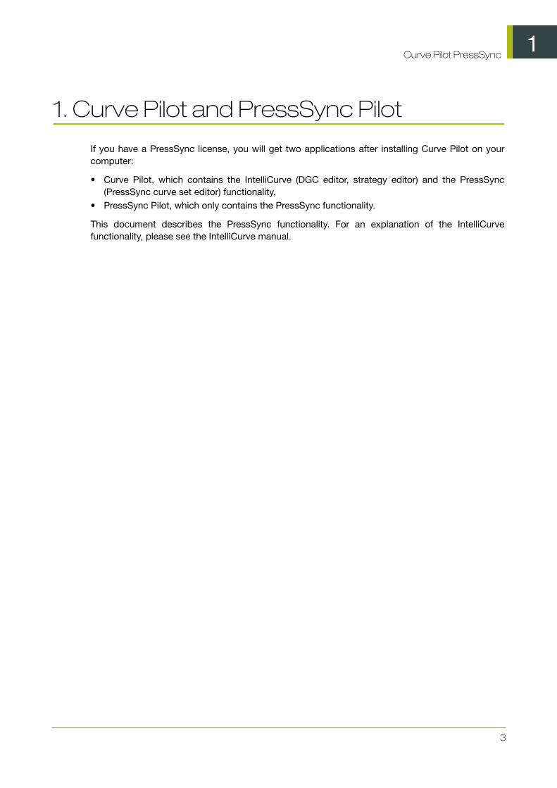
• The letter (A to H) describes how the press behaves in highlights and shadows (the slope): an Acurve makes the press print darker in highlights and lighter in shadows (for presses who have theopposite problem), while an H curve, on the contrary, makes the press print lighter in highlightsand darker in shadows.
An E curve is halfway in between and has a straight slope: it corrects the output the same waythroughout the range. Use it for presses whose output is consistent in hightlights, midtones andshadows.
• The number indicates how much the 50% dot (midtone) prints to: an E20 curve compensates the50% dot to 20%, while an E70 curve compensates 50% to 70%.
Minimum and Maximum Values
A PressSync curve can also contain information about a minimum and a maximum value.
2Curve Pilot PressSync
5
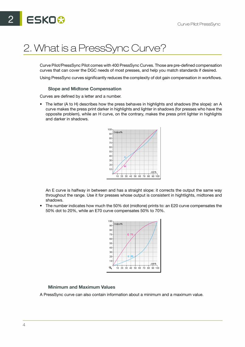
• The minimum value is what the first non-zero value on the curve prints to. So if the minimum isset to 6%, the first non-zero value will print to 6% (as below).
Note:
• This will not change the 0% value. 0% will always print to 0% (it won't be screened), regardlessof the minimum value you choose.
• The smallest percentage in a job can be higher than the minimum value (further on the curve).• If you do not set a minimum value, it is by default set to 0%.
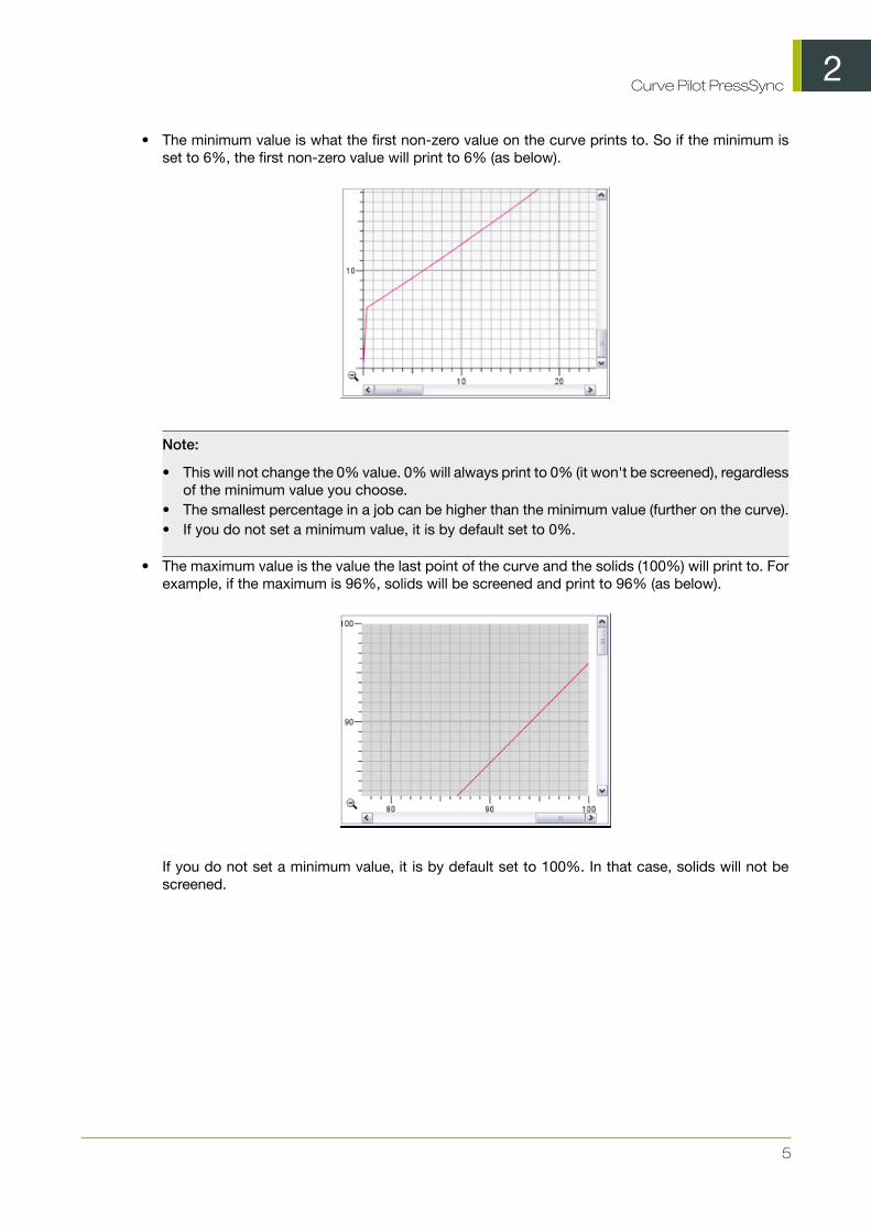
• The maximum value is the value the last point of the curve and the solids (100%) will print to. Forexample, if the maximum is 96%, solids will be screened and print to 96% (as below).
If you do not set a minimum value, it is by default set to 100%. In that case, solids will not bescreened.

3Curve Pilot PressSync
6
3. Finding a PressSync Curve for a PrintingInk
To find a PressSync curve for an individual ink, you need to print a vignette of this ink, measure itand enter the values into Curve Pilot.
Note: You can only do this in Curve Pilot, not PressSync Pilot.
1. Print a vignette of the ink you want to compensate with a PressSync curve (without using anydot gain compensation).
2. In Curve Pilot, go to File > New > DGC (.dgc) .
3. Enter your ink measurements as you would when creating a DGC curve (see the IntelliCurvemanual for details).
4. In the Show Curves area, make sure Compensation curve is selected, then select PressSynccurve.This shows the best PressSync curve to use for your ink and printing conditions (press,substrate...) with a red dotted line on the graph.

3Curve Pilot PressSync
7
You can see the PressSync curve name beside PressSync curve.
By default, the PressSync curve shown is the one that fits the compensation points the best. Thecompensation points are the compensation values for each measurement you have entered (theyare shown as blue crosses on the graph).
5. If you want a PressSync curve that fits the smoothed compensation curve (blue curve) better(instead of the compensation points), select Use Smoothed Curve.

3Curve Pilot PressSync
8
6. If desired, enter a Minimum Value and a Maximum Value to use for your PressSync curve (seeMinimum and Maximum Values for information).
The minimum and maximum values you entered are shown beside the curve name.
7. Save your curve:
a) go to File > Save ,b) enter a (meaningful) File Name for your PressSync curve,c) click OK.
4Curve Pilot PressSync
9
4. Using Your PressSync Curves in Nexus
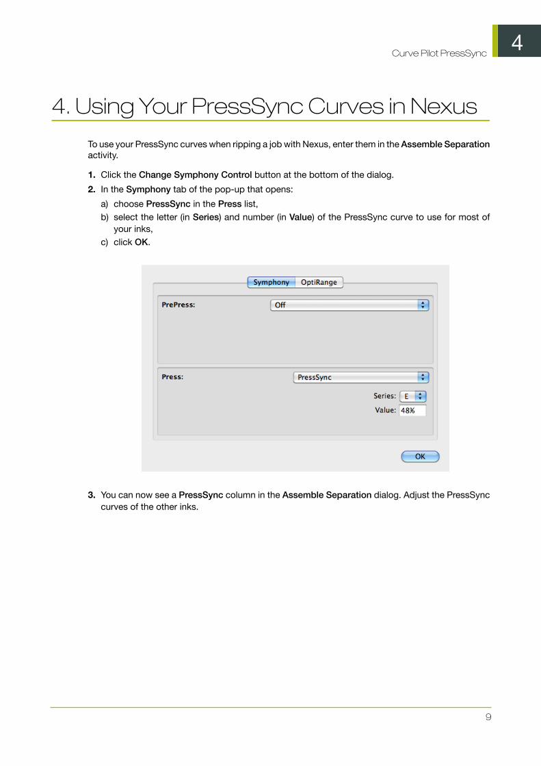
To use your PressSync curves when ripping a job with Nexus, enter them in the Assemble Separationactivity.
1. Click the Change Symphony Control button at the bottom of the dialog.
2. In the Symphony tab of the pop-up that opens:
a) choose PressSync in the Press list,b) select the letter (in Series) and number (in Value) of the PressSync curve to use for most of
your inks,c) click OK.
3. You can now see a PressSync column in the Assemble Separation dialog. Adjust the PressSynccurves of the other inks.

4Curve Pilot PressSync
10

5Curve Pilot PressSync
11
5. What is a PressSync Curve Set?
A PressSync curve set is a bundle of PressSync curves, each attached to an ink (a process ink orany spot color defined in the EskoArtwork CMS database).
It can also contain:
• a target curve (for example a standard) that you want to match,• print measurements used to find the right PressSync curve for each ink,• a history of the measurements done, the curves used, etc.
How to Use It
You select your PressSync curve set (.prsync file) when sending your job to the FlexRIP, so eachjob separation is compensated with the appropriate PressSync curve.
PressSync Curve Sets With or Without Measurements
When creating a curve set, you can either:
• match the PressSync curves to your inks manually,• measure a few press runs and have Curve Pilot/PressSync Pilot find the best curves for you.
We recommend you use measurements.
6Curve Pilot PressSync
12
6. Creating a PressSync Curve Set forYour Press
You can create either :
• An empty curve set: manually pick the PressSync curves for your inks without measuring yourpress output (for example if a third-party application gave you specific PressSync Curves to use).
• A curve set with measurements: measure a few press runs and compare them to target valuesto get your PressSync curves.
This way you can match a specification (ISO, GRACol, SWOP...) or another reference (if forexample you have a good curve set for one of your presses, and want to make a similar one fora second press).
Note: We recommend you create a curve set with measurements, rather than matching thePressSync curves to your inks manually.
6.1 Creating an Empty Curve Set
You can create an empty curve set if you are not planning to measure your press runs at all and wantto manually pick the PressSync curves for your inks. Do this for example if a third-party applicationgave you specific PressSync Curves to use.
In Curve Pilot or PressSync Pilot:
1. Go to File > New then select PressSync Curve Set (.prsync).
In PressSync Pilot, you can also click the New... button at the bottom of the PressSync CurveSet Explorer panel.
2. In the Create New Curve Set dialog, choose An empty curve set, and click OK.
This opens a dialog with an empty PressSync curve set.
By default, the curve set contains the four process inks (Cyan, Magenta, Yellow and Black), anda channel called Other Inks (whose compensation will be used for any job ink not defined in thecurve set).
At the start, the Curve Name shows LIN (linear), which means that no compensation curve isapplied to those inks.

6Curve Pilot PressSync
13
3. Click Setup... to open the Setup dialog.
4. Enter your name in Changed by and a Reason for the setup change.
5. If desired, enter a Curve Set Description.
Note: This will be shown in the field of the curve set dialog (you can only edit the contentsof this field from the Setup dialog).
You will enter the Curve Set Name when saving the curve set.
6. Add extra inks to the curve set if desired:
a) click + at the bottom of the Spot Colors list,b) in the Choose Inks dialog, choose the Ink Book,c) choose or enter the Ink Name and click OK.
When entering an ink name manually, you can use the full ink name or the short ink name.Make sure you use either the exact spelling from your CMS database or the official short name.

6Curve Pilot PressSync
14
Note: You can add any ink that is defined in the EskoArtwork CMS database, but you cannotremove the default channels (Cyan, Magenta, Yellow, Black and Other Inks).
Tip:
If you are working on a curve set from/for a different system (with a different CMS), you can addinks that are not registered in your CMS database:
1. Select <unregistered ink book> in the Ink Book field.2. Type the name of your ink book.3. The Ink Name field will show <unregistered ink>. Type the name of your ink.4. You will see a warning. Click OK.
When working with unregistered inks, you will see a "U" icon ( ).
7. Click OK when you are done with the setup.
8. To assign curves manually to your inks:
a) Click Select Curve Names... in the curve set dialog.b) In the Select Curve Names dialog that opens, choose a PressSync Curve for each ink: choose
the letter, the number and enter a minimum and maximum value if necessary.

6Curve Pilot PressSync
15
Note: Linear means that no curve is assigned to the ink (so no dot gain compensation isapplied).
6Curve Pilot PressSync
16
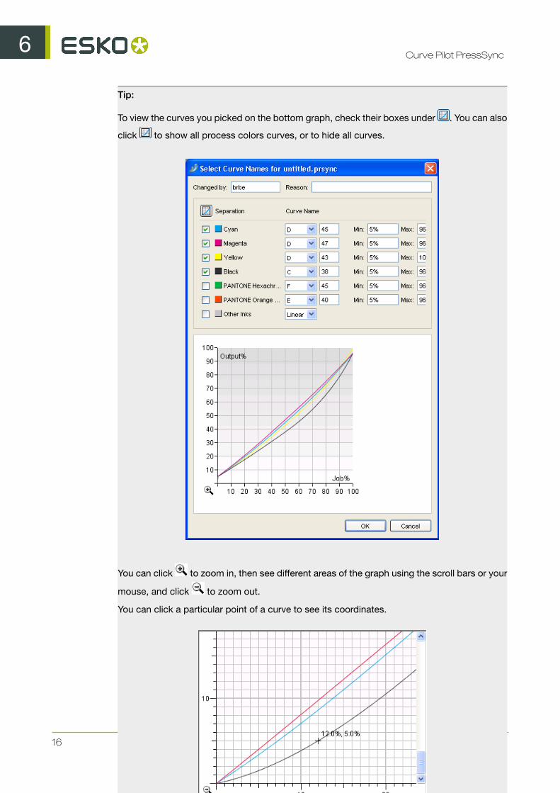
Tip:
To view the curves you picked on the bottom graph, check their boxes under . You can also
click to show all process colors curves, or to hide all curves.
You can click to zoom in, then see different areas of the graph using the scroll bars or your
mouse, and click to zoom out.
You can click a particular point of a curve to see its coordinates.

6Curve Pilot PressSync
17
c) Click OK when you are done.
You can now see the curves you have picked in the curve set dialog.
You can also view them on the graph, and zoom in and out.
9. Save your curve set:
a) Go to File > Save or use Ctrl+S.b) Give your curve set a name and click OK.
6.2 Creating a Curve Set from Measurements
To create a curve set with measurements, you need to measure a few press runs and compare themto target values.

6Curve Pilot PressSync
18
You can either:
• Start from a standard curve set (delivered with Curve Pilot), if you want to compensate your pressoutput to match a target curve from a specification (ISO, GRACol, SWOP...).
• Start from an existing curve set, if you have already created a PressSync curve set that you wantto use as a basis for your new curve set. Do this for example if you have a good curve set for oneof your presses, and you want to make a similar one for a second press.
In both cases, you can use the predefined/existing setup and only take measurements from a fewpress runs, or modify the setup to fit your needs before measuring your output.
1. Go to File > New then select PressSync Curve Set (.prsync).
In PressSync Pilot, you can also click the New... button at the bottom of the PressSync CurveSet Explorer panel.
2. In the Create New Curve Set dialog:
a) choose either A standard or An existing curve set,b) select the curve set you want to start from in the list,
Important:
Make sure you pick a curve set with the type of target you want, as you won't be able tochange it afterwards.
When starting from a standard, the standard name indicates the type of target you will haveto measure:
• standard names starting with 3ck (for example "3ck_GRAColG7.prsync") work with a 3colors + K target (you will have to measure patches for two colors: a Cyan-Magenta-Yellowcomposite and Black),
• standard names starting with cmyk (for example "cmyk_ISO_Newsprint.prsync") work witha CMYK target (you will have to measure patches for four colors: Cyan, Magenta, Yellowand Black).
Existing curve sets have the names you have given them. We recommend you include areference to the target in the curve set names. If you haven't, you can open the existing curveset to check what kind of target it uses (in the Process Colors Setup on page 21) beforecreating a new curve set from it.
Do not start from an "empty" existing curve set when creating a curve set with measurements.
c) click OK.
This opens an untitled.prsync curve set in a dialog, with the inks and setup of the standard/existing curve set you selected.
If you started from a standard curve set, you will see the four process inks (Cyan, Magenta, Yellowand Black), and a channel called Other Inks (whose compensation will be used for any job inkthat isn't defined in the curve set).
At the start, each Curve Name shows LIN (linear), which means that no compensation curve isapplied on those inks.

6Curve Pilot PressSync
19
3. Customize your setup.
4. Take press run measurements to find the best PressSync Curve to use for each ink (see TakingPress Runs Measurements on page 28).
We recommend print and measure a Universal Target then production jobs with a control strip.
5. Save your curve set:
a) Go to File > Save or use Ctrl+S.b) Give your curve set a name and click OK.
6.2.1 Customizing Your Setup
1. Click the Setup... button in the curve set dialog to open the Setup dialog.
2. Use the Setup dialog to:
6Curve Pilot PressSync
20
• define the target values that your measurements will be compared to (for Process Colors,Gray Balance and Spot Colors),
• add or remove spot colors to be compensated by your curve set.
For details, see:
• General Setup on page 20,• Process Colors Setup on page 21,• Gray Balance Setup on page 24,• Spot Colors Setup on page 26.
3. Click OK when you are done with the setup.
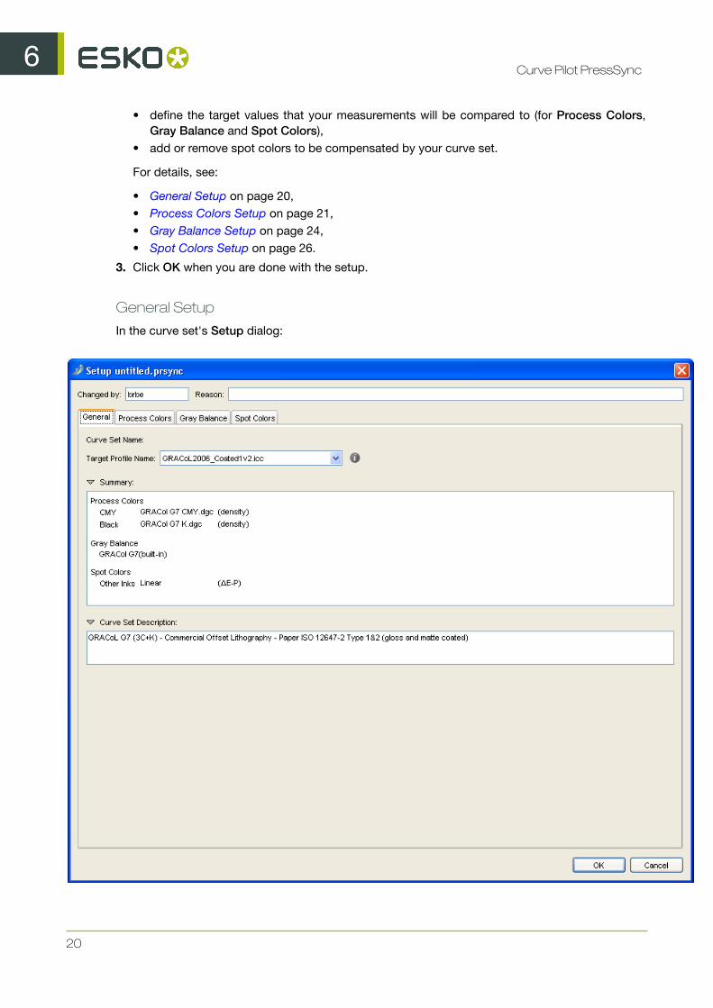
General Setup
In the curve set's Setup dialog:

6Curve Pilot PressSync
21
1. Enter your name in Changed by and a Reason for the setup change.
You will enter the Curve Set Name when saving the curve set.
2. If you want to calculate the reference values (to compare your measurements to) from an iccprofile, select it in Target Profile Name.
If you started from a standard curve set, the corresponding icc profile is selected by default (forexample, GRACol2006_Coated1v2.icc if you started from 3ck_GRAColG7.prsync).
You can also select <none>, if you want to define the reference values manually.
Note: You can click on to see information about the selected target profile.
You will see a Summary of the target curves selected for process colors, gray balance and spotcolors.
3. If desired, enter/change the Curve Set Description.
Note: This will be shown in the field of the curve set dialog (you can only edit the contentsof this field from the Setup dialog).
Process Colors Setup
In the Process Colors tab, you need to choose how to measure your process colors on print (ona universal target or a control strip on the side of a job), and what target values to compare yourmeasurements to.

6Curve Pilot PressSync
22
Note:
Depending on the curve set you started from (see Creating a Curve Set from Measurements on page17), you will need to choose either:
• target references / values for CMY and for Black,• target references / values for Cyan, Magenta, Yellow and Black.
1. Choose the unit of Measure to use for your press runs measurements. You can choose:
• density, to measure your patches with a "Status E" (for Europe) or "Status T" (for the US)densitometer,
• %DotArea, to measure how much of the area is taken by the dot (in percentage),

6Curve Pilot PressSync
23
• DeltaE-P, to measure the color difference between patch and paper (this is illuminantdependant and based on CIE-1976),
• %DeltaE-SP, to measure the color difference between patch and paper, proportionally to thecolor difference between solid and paper (this is illuminant dependant and based on CIE-1976).
Tip: Click to see more information about the units.
You will need a densitometer if you choose density or %DotArea, and a spectrophotometer ifyou choose DeltaE-P or %DeltaE-SP.
This unit will be used to define the desired values for Paper and Solid, Universal Target andControl Strip below.
2. In Target Curves, choose how to calculate the target values for process colors. You can either:
• Select Use Profile for Tone Target Curves if you want to use data from the Target Profile youselected in the General tab to calculate target values.
When you select this, the CMY and Black (or Cyan, Magenta, Yellow and Black) lists will begreyed out.
• Select Linear (in the lists) if you want linear print values (without dot gain) as target values.• Select User Defined if you want to enter the target values manually instead of getting them
from a curve or a profile.• Select any reference dgc curve present in the DGC or Curves database to calculate the target
values.
Tip: If you want to start from predefined values but refine them for your needs, select thepredefined values first (Target Profile, Linear or a reference dgc curve) then select User Defined.This will keep the predefined values but you will be able to edit them.
3. Check the desired values for Paper and Solid, and adjust them as necessary.
For example, if you chose to work with densities, adjust the density of paper and solid asnecessary.
4. For the Universal Target:
• If you have chosen User Defined in your Target Curves, enter the desired values for 1/4, 1/2and 3/4 tones.
Note: The Paper and Solid values are fixed. They are either 0% and 100% (if you are using%DotArea or %DeltaE-SP as unit) or the values you entered for Paper and Solid (if you areusing density or DeltaE-P as unit).
• Otherwise, the values are calculated automatically based on what you chose in Target Curves.
5. For the Control Strip:
• If you have chosen User Defined in your Target Curves, enter the number of Patches youwant to measure, their percentages and their desired values.
Note: The values of the 0% and the 100% patch are fixed. They are either 0% and 100%(if you are using %DotArea or %DeltaE-SP as unit) or the values you entered for Paper andSolid (if you are using density or DeltaE-P as unit).
• Otherwise, the values are calculated automatically based on what you chose in Target Curves,but you can still select the number of Patches and their percentages.

6Curve Pilot PressSync
24
Gray Balance Setup
Checking Gray Balance is printing different intensities of gray using Cyan, Magenta and Yellow inks,and measuring Lab values on the print to check how neutral the gray is.
In the Gray Balance tab, you need to choose what target values to compare your gray printsmeasurements to (for prints on a universal target or a control strip on the side of a job).
1. In Target, choose how to calculate the target values for gray balance. You can either:
• Select From Target Profile if you want to use data from the Target Profile you selected in theGeneral tab to calculate target values.
• Select User Defined if you want to enter the target values manually instead of getting themfrom a curve or a specification.

6Curve Pilot PressSync
25
• Select Neutral Paper if you want to calculate the target values relatively to the paper and solid(using the paper's Lab values as 0% gray, the solid's as 100%, and calculating the values inbetween).
• Select the built-in gray target of the specification (for example GRAColG7 (built-in) if youstarted from 3ck_GRAColG7.prsync) to calculate the target values.
You can click on to see information about the selected target.
Tip: If you want to start from predefined values but refine them for your needs, select thepredefined values first (Target Profile, Neutral Paper or the built-in target of the specification)then select User Defined. This will keep the predefined values but you will be able to edit them.
2. The Universal Target will contain a Light and a Dark gray square, composed of cyan, magentaand yellow, with the cyan values fixed at respectively 25% and 50%.
• If you have chosen User Defined as Target:
• enter the desired magenta and yellow values for the Light and the Dark gray squares,• enter the desired Lab values of the cyan-magenta-yellow combination for the Light and
the Dark gray squares,• enter the desired Lab values of the Paper and the Solid patch (100% cyan, 100% magenta
and 100% yellow).• If you have chosen Neutral Paper as Target, enter the desired Lab values of the Paper and
the Solid patch.
The target values for the Light and Dark gray squares are calculated automatically.• If you selected either the built-in gray target of the specification or the target profile as Target,
all the target values are calculated automatically.
3. The Control Strip on the side of a production job will contain patches of gray composed of cyan,magenta and yellow.
• If you have chosen User Defined as Target:
• enter the number of Patches you want to measure,• enter the percentages of cyan, magenta and yellow to print for each of those patches,• enter the desired Lab values of your patches, the Paper and the Solid patch (100% cyan,
100% magenta and 100% yellow).• If you have chosen Neutral Paper as Target:
• enter the number of Patches you want to measure,• enter the percentage of cyan to print for each patch (the percentages of magenta and
yellow are calculated automatically),• enter the desired Lab values of the Paper and the Solid patch (100% cyan, 100% magenta
and 100% yellow).• If you selected either the built-in gray target of the specification or the target profile as Target,
enter the number of Patches you want to measure and the percentage of cyan to print foreach patch.
All the other values are calculated automatically.
4. If you have chosen User Defined or Neutral Paper, you can also set desired Lab values for theSolid Process Colors if desired (you can get those from your ink vendor).
Otherwise those values are defined automatically.

6Curve Pilot PressSync
26
Spot Colors Setup
In the Spot Colors tab, you can add or remove spot colors. For each spot color you add, you canchoose how to measure it on print (on a universal target or a control strip on the side of a job), andwhat target values to compare your measurements to.
You can also define what to do when encountering job spot colors that aren't defined in the setup.
1. To add a spot color:
a) click + at the bottom of the Spot Colors list,b) in the Choose Inks dialog, choose the Ink Book,c) choose or enter the Ink Name and click OK.

6Curve Pilot PressSync
27
When entering an ink name manually, you can use the full ink name or the short ink name.Make sure you use either the exact spelling from your CMS database or the official short name.
Note: You can add any ink that is defined in the EskoArtwork CMS database, but you cannotremove the default channels (Cyan, Magenta, Yellow, Black and Other Inks).
Tip:
If you are working on a curve set from/for a different system (with a different CMS), you can addinks that are not registered in your CMS database:
1. Select <unregistered ink book> in the Ink Book field.2. Type the name of your ink book.3. The Ink Name field will show <unregistered ink>. Type the name of your ink.4. You will see a warning. Click OK.
When working with unregistered inks, you will see a "U" icon ( ).
2. Select the spot color you added to define its setup.
3. Choose the unit of Measure to use for your press runs measurements. You can choose:
• density, to measure your patches with a "Status E" (for Europe) or "Status T" (for the US)densitometer,
• %DotArea, to measure how much of the area is taken by the dot (in percentage),• DeltaE-P, to measure the color difference between patch and paper (this is illuminant
dependant and based on CIE-1976),• %DeltaE-SP, to measure the color difference between patch and paper, proportionally to the
color difference between solid and paper (this is illuminant dependant and based on CIE-1976).
Tip: Click to see more information about the units.
You will need a densitometer if you choose density or %DotArea, and a spectrophotometer ifyou choose DeltaE-P or %DeltaE-SP.
This unit will be used to define the desired values for Paper and Solid, Universal Target andControl Strip below.
4. Choose how to calculate the target values for this spot color. You can either:
• Select Linear if you want linear print values (without dot gain) as target values.• Select User Defined if you want to enter the target values manually instead of getting them
from a curve.• Select any reference dgc curve present in the DGC or Curves database to calculate the target
values (only when measuring density or %DotArea).
Tip: If you want to start from predefined values but refine them for your needs, select thepredefined values first (Linear, or a reference dgc curve) then select User Defined. This will keepthe predefined values but you will be able to edit them.
5. Check the desired values for Paper and Solid, and adjust them as necessary.
For example, if you chose to work with densities, adjust the density of paper and solid asnecessary.
6. For the Universal Target:

6Curve Pilot PressSync
28
• If you have chosen User Defined, enter the desired values for 1/4, 1/2 and 3/4 tones.
Note: The Paper and Solid values are fixed. They are either 0% and 100% (if you are using%DotArea or %DeltaE-SP as unit) or the values you entered for Paper and Solid (if you areusing density or DeltaE-P as unit).
• Otherwise, the values are calculated automatically based on what you chose (Linear printingor a reference dgc curve).
7. For the Control Strip:
• If you have chosen User Defined, enter the number of Patches you want to measure, theirpercentages and their desired values.
Note: The values of the 0% and the 100% patch are fixed. They are either 0% and 100%(if you are using %DotArea or %DeltaE-SP as unit) or the values you entered for Paper andSolid (if you are using density or DeltaE-P as unit).
• Otherwise, the values are calculated automatically based on what you chose, but you can stillselect the number of Patches and their percentages.
6.2.2 Taking Press Runs Measurements
We recommend you first print and measure a Universal Target to find the initial curves, then refinethose curves by printing production jobs and measuring their control strips.
Measuring a Universal Target
The Universal Target is a test form designed by EskoArtwork for setting up dot gain compensationcurves for your press. It is typically used when you have no idea about what PressSync curves to use.
It contains:
• four single-color vignettes (Cyan, Magenta, Yellow and Black),• a gray vignette composed of Cyan, Magenta and Yellow,• a light and dark gray squares (composed of a fixed Cyan percentage with varying Magenta and
Yellow percentages) to calibrate gray balance.

6Curve Pilot PressSync
29
When measuring a Universal Target, you will look for where the target values (defined in the setup)are in the vignettes. This will be used to calculate PressSync curves for each ink.
For example, if you find the target value for 50% Black at 40%, Curve Pilot will know that the Blackcurve needs to compensate a 10% dot gain in the midtones.
1. Print a Universal Target without any dot gain compensation.
Note:
If you have a good starting value, you can create a preliminary curve set and use it to RIP andprint the universal target.
For example, if you usually need to drop your midtones by 10%, you can use a curve set containingan E40 curve for each ink. Concentric Screening users usually start from C45 curves.
See Using Your PressSync Curves in Nexus on page 9 or Using a PressSync Curve Set in FlexRipon page 44 for details.
2. Click the Measure... button in the curve set dialog to open the Measure Curve Set dialog.
3. Select Universal Target and click OK.
This opens the Measure Universal Target dialog.
4. Enter your name in Changed by and a Reason for the setup change.
5. In most cases, you don't need to set anything in the Universal Target tab.
However, if you have printed the Universal Target with a preliminary curve set (see step 1), youshould:
• select The Universal Target is printed with different PressSync Curves,
6Curve Pilot PressSync
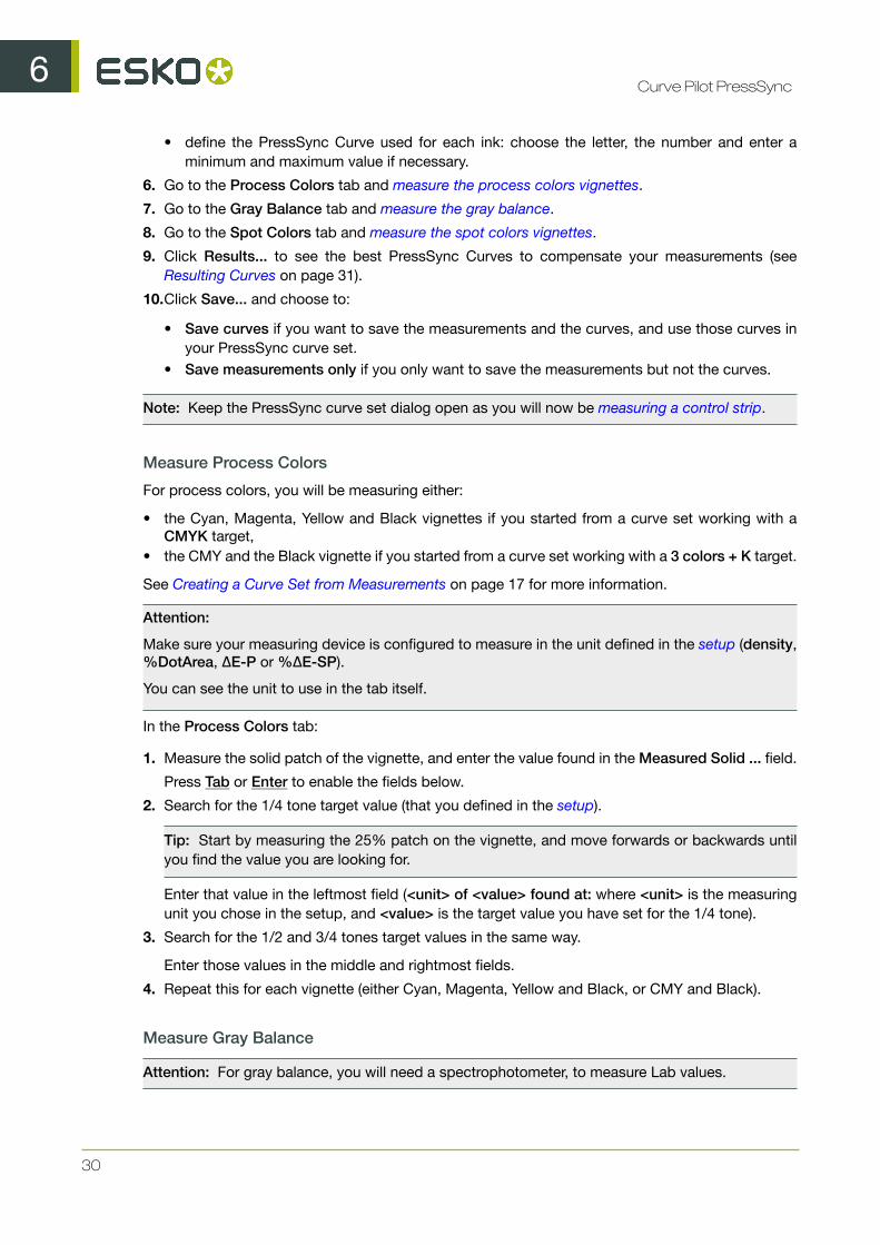
30
• define the PressSync Curve used for each ink: choose the letter, the number and enter aminimum and maximum value if necessary.
6. Go to the Process Colors tab and measure the process colors vignettes.
7. Go to the Gray Balance tab and measure the gray balance.
8. Go to the Spot Colors tab and measure the spot colors vignettes.
9. Click Results... to see the best PressSync Curves to compensate your measurements (seeResulting Curves on page 31).
10.Click Save... and choose to:
• Save curves if you want to save the measurements and the curves, and use those curves inyour PressSync curve set.
• Save measurements only if you only want to save the measurements but not the curves.
Note: Keep the PressSync curve set dialog open as you will now be measuring a control strip.
Measure Process Colors
For process colors, you will be measuring either:
• the Cyan, Magenta, Yellow and Black vignettes if you started from a curve set working with aCMYK target,
• the CMY and the Black vignette if you started from a curve set working with a 3 colors + K target.
See Creating a Curve Set from Measurements on page 17 for more information.
Attention:
Make sure your measuring device is configured to measure in the unit defined in the setup (density,%DotArea, ΔE-P or %ΔE-SP).
You can see the unit to use in the tab itself.
In the Process Colors tab:
1. Measure the solid patch of the vignette, and enter the value found in the Measured Solid ... field.
Press Tab or Enter to enable the fields below.
2. Search for the 1/4 tone target value (that you defined in the setup).
Tip: Start by measuring the 25% patch on the vignette, and move forwards or backwards untilyou find the value you are looking for.
Enter that value in the leftmost field (<unit> of <value> found at: where <unit> is the measuringunit you chose in the setup, and <value> is the target value you have set for the 1/4 tone).
3. Search for the 1/2 and 3/4 tones target values in the same way.
Enter those values in the middle and rightmost fields.
4. Repeat this for each vignette (either Cyan, Magenta, Yellow and Black, or CMY and Black).
Measure Gray Balance
Attention: For gray balance, you will need a spectrophotometer, to measure Lab values.

6Curve Pilot PressSync
31
In the Gray Balance tab:
1. Measure the Lab values of the substrate and enter them in the L, a and b fields.
Press Tab or Enter to enable the fields below.
2. In the Dark Square, find the Lab target value defined in the setup.
Enter the coordinates of the position where you found that value (the X coordinate is a letter, theY coordinate a number).
3. In the Light Square, find the Lab target value defined in the setup.
Enter the coordinates of the position where you found that value.
Measure Spot Colors
Although the Universal Target is designed to be used for process colors, you can also use it to printand measure spot colors.
To do this, make a copy of the Universal Target PDF file, and create a version that also containsvignettes for the required spot colors (copy one of the process colors' vignettes and change its inksettings).
Note: The spot colors you use must be defined in the curve set setup.
Attention:
Make sure your measuring device is configured to measure in the unit defined in the setup (density,%DotArea, DeltaE-P or %DeltaE-SP).
You can see the unit to use in the tab itself (for spot colors, it is usually a colorimetric unit: DeltaE-P or %DeltaE-SP).
In the Spot Colors tab:
1. Measure the solid patch of the first spot color vignette, and enter the value found in the MeasuredSolid ... field.
Press Tab or Enter to enable the fields below.
2. Search for the 1/4 tone target value (that you defined in the setup).
Tip: Start by measuring the 25% patch on the vignette, and move forwards or backwards untilyou find the value you are looking for.
Enter that value in the leftmost field (<unit> of <value> found at: where <unit> is the measuringunit you chose in the setup, and <value> is the target value you have set for the 1/4 tone).
3. Search for the 1/2 and 3/4 tones target values in the same way.
Enter those values in the middle and rightmost fields.
4. Repeat this for each spot color vignette, including Other Inks.
Resulting Curves
1. When you have entered all your measurements, click Results... to see the best PressSync curvesto use.
6Curve Pilot PressSync
32
Note:
You can also do this after entering the measurements for one or more inks, to see curve(s) for theink(s). For example, enter the Cyan measurements and click Results... to see the Cyan curve.
You can then click Back To Measurements to go back and enter the rest of your measurements.
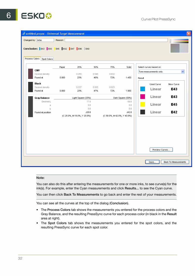
You can see all the curves at the top of the dialog (Conclusion).
• The Process Colors tab shows the measurements you entered for the process colors and theGray Balance, and the resulting PressSync curve for each process color (in black in the Resultarea at right).
• The Spot Colors tab shows the measurements you entered for the spot colors, and theresulting PressSync curve for each spot color.
6Curve Pilot PressSync
33
Note:
If the PressSync curve found for an ink doesn't fit the compensation points calculated from themeasurements properly, it will be shown in red.
If no PressSync curve could be calculated because there are no or invalid measurements, youwill see -- instead of a curve name.
In that case, you can click the Back To Measurements button to verify your measurements.
If your measurements are correct (your press just prints that way), you should use Dot GainCompensation instead of PressSync curves. See the IntelliCurve manual.
2. In the Process Colors tab, you can:
a) Choose if you want to compensate mostly colors or mostly neutrals: in Select curves basedon, choose either:
• Tone measurements only if you want to pick curves that compensate mostly processcolors, and not gray balance,
• Both Tone and Gray Balance measurements if you want to pick average curves thatcompensate everything (process colors and gray balance),
• Mainly Gray Balance measurements if you want to pick curves that compensate mostlygray balance, and not process colors.
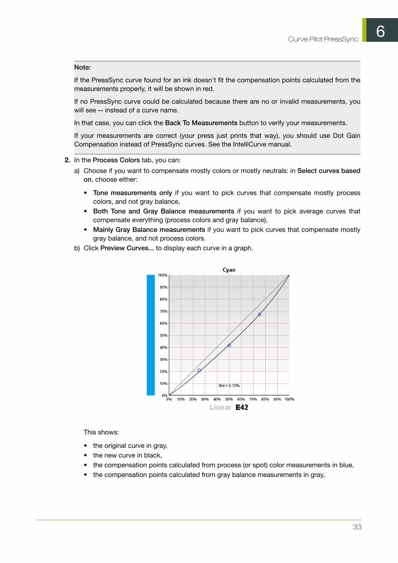
b) Click Preview Curves... to display each curve in a graph.
This shows:
• the original curve in gray,• the new curve in black,• the compensation points calculated from process (or spot) color measurements in blue,• the compensation points calculated from gray balance measurements in gray,

6Curve Pilot PressSync
34
• the standard deviation (Std), that shows how far the curve is from the compensation points(this should be under 2% for the curve to fit properly).
Depending on what you chose for gray balance importance, the curve will be closer to theprocess color compensation points or the gray balance compensation points.
3. In the Spot Colors tab, you can click Preview Curves... to display each curve in a graph.
4. Click Save... and choose to:
• Save curves if you want to save the measurements and the curves, and use those curves inyour PressSync curve set.
Note: If the Result area showed -- instead of a curve name, that ink's previous curve will notbe changed.
• Save measurements only if you only want to save the measurements but not the curves.
This will save the measurement as incomplete, but you can edit it again or save the curveslater (see Continuing an Incomplete Measurement on page 39).
Measuring a Control Strip of a Production Sheet
We recommend you print a production job using the PressSync curves you found after measuring theUniversal Target. This job should have a control strip, that you will measure to refine your PressSynccurves.
Note:
You can use any type of control strip that contains several patches of each ink (for example 25%,50%, 75% and 100%).
Make sure the patches of your control strip and what you have defined in the setup match. If you donot have a control strip matching your setup, change the setup (see Process Colors Setup on page21, Gray Balance Setup on page 24 and Spot Colors Setup on page 26).
1. Use FlexRip or Nexus to RIP and print a production job (containing a control strip) using thePressSync curves you found after measuring the Universal Target.
See Using Your PressSync Curves in Nexus on page 9 or Using a PressSync Curve Set in FlexRipon page 44 for details.
2. Back in your Curve Pilot curve set, click the Measure... button again.
3. In the Measure Curve Set dialog that opens, select A control strip of a production sheet andclick OK.
This opens the Measure Production Sheet dialog.
4. Enter your name in Changed by and a Reason for the setup change.
5. In most cases, you don't need to set anything in the Production Sheet tab.
However, if for some reason you have printed the Production Sheet with a different curve set thanthe one you found from the Universal target measurements, you should:
• select The production sheet is printed with different PressSync Curves,• define the PressSync Curve used for each ink: choose the letter, the number and enter a
minimum and maximum value if necessary.
6. Go to the Process Colors tab and measure the process colors vignettes.
6Curve Pilot PressSync
35
7. Go to the Gray Balance tab and measure the gray balance.
8. Go to the Spot Colors tab and measure the spot colors vignettes.
9. Click Results... to see the best PressSync Curves to compensate your measurements (seeResulting Curves on page 36).
10.Click Save... and choose to:
• Save curves if you want to save the measurements and the curves, and use those curves inyour PressSync curve set.
• Save measurements only if you only want to save the measurements but not the curves.
Measure Process Colors
For process colors, you will be measuring either:
• the Cyan, Magenta, Yellow and Black vignettes if you started from a curve set working with aCMYK target,
• the CMY and the Black vignette if you started from a curve set working with a 3 colors + K target.
See Creating a Curve Set from Measurements on page 17 for more information.
Attention:
Make sure your measuring device is configured to measure in the unit defined in the setup (density,%DotArea, ΔE-P or %ΔE-SP).
You can see the unit to use in the tab itself.
In the Process Colors tab:
1. Depending on what you have defined in the setup:
• Measure the 0% and 100% patches, and enter the values found in the corresponding fields.• Measure the solid patch, and enter the value found in the Measured Solid ... field.
You can see the desired value(s) defined in the setup between brackets.
Press Tab or Enter to enable the other fields.
2. Measure the other patches (defined in the setup) and enter the values found in the correspondingfields.
You will see the desired values (defined in the setup) below those fields.
3. Repeat this for each vignette (either Cyan, Magenta, Yellow and Black, or CMY and Black).
Measure Gray Balance
Attention: For gray balance, you will need a spectrophotometer, to measure Lab values.
In the Gray Balance tab:
1. Measure the Lab values of the substrate and enter them in the L, a and b fields below.
You can see the desired values (defined in the setup) between brackets below.
2. Measure the Lab values of the solid (100%) patch and enter them in the L, a and b fields underthe white patch.
6Curve Pilot PressSync
36
Press Tab or Enter to enable the other fields.
3. Measure the other patches (defined in the setup) and enter the Lab values found in thecorresponding fields.
You will see the desired values below those fields.
Tip: The numbers in the patches indicate the CMY composition (for example: 25, 19, 19 is 25%Cyan, 19% Magenta and 19% Yellow).
Measure Spot Colors
Note: The spot colors you use must be defined in the curve set setup.
Attention:
Make sure your measuring device is configured to measure in the unit defined in the setup (density,%DotArea, DeltaE-P or %DeltaE-SP).
You can see the unit to use in the tab itself (for spot colors, it is usually a colorimetric unit: DeltaE-P or %DeltaE-SP).
In the Spot Colors tab:
1. Depending on what you have defined in the setup:
• Measure the 0% and 100% patches, and enter the values found in the corresponding fields.• Measure the solid patch, and enter the value found in the Measured Solid ... field.
You can see the desired value(s) defined in the setup between brackets.
Press Tab or Enter to enable the other fields.
2. Measure the other patches (defined in the setup) and enter the values found in the correspondingfields.
You will see the desired values (defined in the setup) below those fields.
3. Repeat this for each spot color vignette, including Other Inks.
Resulting Curves
1. When you have entered all your measurements, click Results... to see the best PressSync curvesto use.

6Curve Pilot PressSync
37
Note:
You can also do this after entering the measurements for one or more inks, to see curve(s) for theink(s). For example, enter the Cyan measurements and click Results... to see the Cyan curve.
You can then click Back To Measurements to go back and enter the rest of your measurements.
You can see all the curves at the top of the dialog (Conclusion).
• The Process Colors tab shows the measurements you entered for the process colors and theGray Balance, and the resulting PressSync curve for each process color (in black in the Resultarea at right).
• The Spot Colors tab shows the measurements you entered for the spot colors, and theresulting PressSync curve for each spot color.

6Curve Pilot PressSync
38
Note:
If the PressSync curve found for an ink doesn't fit the compensation points calculated from themeasurements properly, it will be shown in red.
If no PressSync curve could be calculated because there are no or invalid measurements, youwill see -- instead of a curve name.
In that case, you can click the Back To Measurements button to verify your measurements.
If your measurements are correct (your press just prints that way), you should use Dot GainCompensation instead of PressSync curves. See the IntelliCurve manual.
2. In the Process Colors tab, you can:
a) Choose if you want to compensate mostly colors or mostly neutrals: in Select curves basedon, choose either:
• Tone measurements only if you want to pick curves that compensate mostly processcolors, and not gray balance,
• Both Tone and Gray Balance measurements if you want to pick average curves thatcompensate everything (process colors and gray balance),
• Mainly Gray Balance measurements if you want to pick curves that compensate mostlygray balance, and not process colors.
b) Click Preview Curves... to display each curve in a graph.
This shows:
• the original curve in gray,• the new curve in black,• the compensation points calculated from process (or spot) color measurements in blue,• the compensation points calculated from gray balance measurements in gray,

6Curve Pilot PressSync
39
• the standard deviation (Std), that shows how far the curve is from the compensation points(this should be under 2% for the curve to fit properly).
Depending on what you chose for gray balance importance, the curve will be closer to theprocess color compensation points or the gray balance compensation points.
3. In the Spot Colors tab, you can click Preview Curves... to display each curve in a graph.
4. Click Save... and choose to:
• Save curves if you want to save the measurements and the curves, and use those curves inyour PressSync curve set.
Note: If the Result area showed -- instead of a curve name, that ink's previous curve will notbe changed.
• Save measurements only if you only want to save the measurements but not the curves.
This will save the measurement as incomplete, but you can edit it again or save the curveslater (see Continuing an Incomplete Measurement on page 39).
Continuing an Incomplete Measurement
When a measurement was saved with the option Save measurements only, the measurement issaved as incomplete (whether you filled in all the measurement fields or not). The PressSync curvesresulting from that measurement are not used for the curve set.
To edit it (if needed) and save the curves, do the following:
1. Make sure the incomplete measurement is active in the History (you should see , not besideit).
If it isn't, make it active (see Reverting to a Previous History Stage on page 43).
2. Click the Measure... button in the curve set dialog.
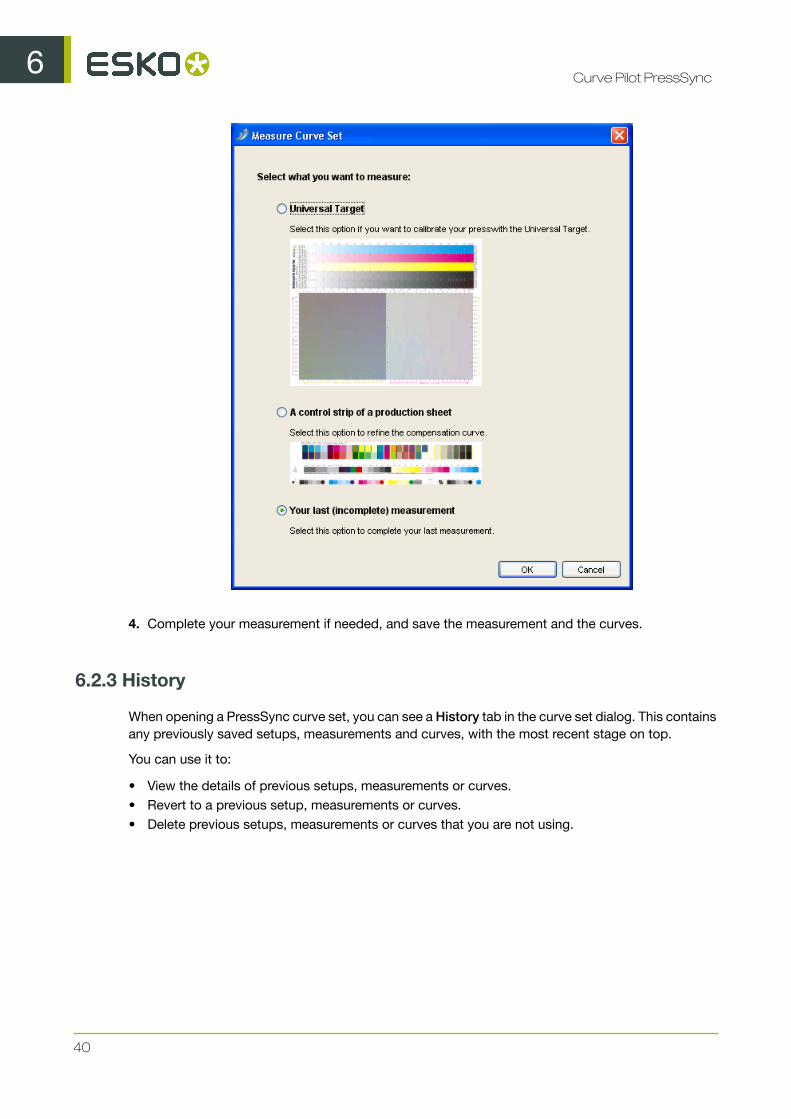
3. In the Measure Curve Set dialog, select Your last (incomplete) measurement and click OK.
6Curve Pilot PressSync
40
4. Complete your measurement if needed, and save the measurement and the curves.
6.2.3 History
When opening a PressSync curve set, you can see a History tab in the curve set dialog. This containsany previously saved setups, measurements and curves, with the most recent stage on top.
You can use it to:
• View the details of previous setups, measurements or curves.• Revert to a previous setup, measurements or curves.• Delete previous setups, measurements or curves that you are not using.

6Curve Pilot PressSync
41
For each history stage, you can see:
• its state:
•currently active ( ),
• active but incomplete measurement ( ),• inactive and incomplete measurement ( ),• inactive and not linked to the current setup (greyed out),
• what has changed (for example Measured Control Strip or Setup Change),• the Curves resulting from that action,• the Date and time of the change.
6Curve Pilot PressSync
42
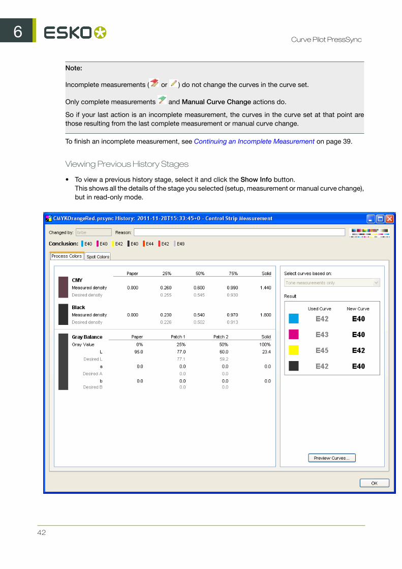
Note:
Incomplete measurements ( or ) do not change the curves in the curve set.
Only complete measurements and Manual Curve Change actions do.
So if your last action is an incomplete measurement, the curves in the curve set at that point arethose resulting from the last complete measurement or manual curve change.
To finish an incomplete measurement, see Continuing an Incomplete Measurement on page 39.
Viewing Previous History Stages
• To view a previous history stage, select it and click the Show Info button.This shows all the details of the stage you selected (setup, measurement or manual curve change),but in read-only mode.

6Curve Pilot PressSync
43
Reverting to a Previous History Stage
• To revert to a previous history stage, select it and click the Set Active button. It will get a green
flag .
• Setting a completed measurement active reverts to the PressSync curves resulting from thatmeasurement.
• Setting an incomplete measurement active reverts to the PressSync curves used to printthe sheet measured.
• Setting a Manual Curve Change active reverts to the PressSync curves set manually at thattime.
• Setting a Setup Change active reverts to the setup version created by the setup change.
This can for example change spot colors or how to measure your prints.
Note: Each measurement made is based on a specific setup version. When changing the setupof the curve set or activating another setup version, the measurements corresponding to othersetup versions will be grayed out.
Deleting a Previous History Stage
To delete previous setups, measurements or curves that you are not using:
• To delete a previous history stage, select it and click the Remove button.
Attention:
You cannot delete:
• active stages (you need to first activate another stage instead),• setup stages used by measurements (you need to delete the measurements before you can
delete the setup).

7Curve Pilot PressSync
44
7. Using a PressSync Curve Set in FlexRip
To use your PressSync curve set when ripping a job with FlexRip, select it in your RIP ticket in theAutomation Engine Pilot.
• In the Dot Gain Compensation area of the RIP ticket, select your PressSync curve set (.prsync)in the Automatic list.

8Curve Pilot PressSync
45
8. Using PressSync Curve Sets in aStrategy
A strategy (.icpro file) is a combination of various curves, which allows you to compensate differentcases (different inks, screen rulings, dots, etc.) in a different way.
A strategy can use DGC curves or/and PressSync curve sets. Each curve or curve set is linked to aspecific case (for example: round dots + 120 lpi + linework).
For more information about strategies, see the IntelliCurve manual.
Note: You can only create strategies in Curve Pilot, not PressSync Pilot.
To use PressSync curve sets in a strategy:
1. Go to File > New > Strategy (.icpro) .
2. Build your strategy: use the buttons at right to create splits for different cases (per ruling/dot/angle/...).
See the IntelliCurve manual for more information.
Note: You shouldn't create splits based on inks as PressSync curve sets already perform ink-based compensation.
3. For each case needing a PressSync curve set:
a)click the DGC button and choose to use a PressSync curve set,
b) click the <none> column in the middle and select the PressSync curve set to use in the list.
You can see the curves of the selected curve set at the bottom of the strategy editor.

8Curve Pilot PressSync
46
Note: If you want, you can click Open... to open the selected curve set (to check or edit it).
4. Save your strategy under a meaningful name.
9Curve Pilot PressSync
47
9. Viewing Curve Sets in the PreviewCombined Curves Tool
The Preview Combined Curves tool is useful when working with curve sets and/or strategies. It letsyou check which curve of the curve set/strategy will be used in a specific case (ink, ruling, dot...).
It can also simulate what happens when using a combination of curves, for example platecompensation together with press compensation.
9.1 Previewing a PressSync Curve in a Curve Set
1. Go to Tools > Preview Combined Curves...
2. Depending on where you will use your PressSync curve set, select it either in the Automatic Pressor the Automatic Plate Making list.
3. In the Context area, select the ink whose compensation curve you want to preview:
a) in Ink Group, select the ink book containing your ink,b) select your ink in Ink Name.
4. In the Curves area, you will see the name of the PressSync curve that will be used for your ink.
You will also see the curve drawn on the graph.

9Curve Pilot PressSync
48
9.2 Previewing a PressSync Curve Set in a Strategy
1. Go to Tools > Preview Combined Curves...
2. Depending on where you will use your strategy, select it either in the Automatic Press or theAutomatic Plate Making list.
3. In the Context area, define the case you are interested in:
a) Select either Images (CT) or Linework (LW).b) Select the ink book containing your ink in Ink Group, and the ink in Ink Name.c) Select the Dot Shape, Ruling and Angle you are interested in.
If some of those criteria are not relevant for your case, your don't need to fill them in.
4. In the Curves area, you will see the name of the PressSync curve that will be used in the caseyou defined.

9Curve Pilot PressSync
49
You will see the curve drawn on the graph.
9.3 Previewing a Combination of Curves
You can also use the Preview Combined Curves to see the compensation that will be applied whenusing both press and plate curves.
1. Go to Tools > Preview Combined Curves...
2. Select the compensation to use:
• for your press in the Automatic Press list,• for your plate in the Automatic Plate Making list.

9Curve Pilot PressSync
50
You can select .icpro strategies, .prsync curve sets or legacy .scrdgc screen-based DGCfiles.
3. In the Context area, define the case you are interested in:
a) Select either Images (CT) or Linework (LW).b) Select the ink book containing your ink in Ink Group, and the ink in Ink Name.c) Select the Dot Shape, Ruling and Angle you are interested in.
If some of those criteria are not relevant for your case, your don't need to fill them in.
4. In the Curves area, you will see the curves used both on the press and the plate for the caseyou defined.
On the graph, you will see a curve that is a combination of those two curves.

10Curve Pilot PressSync
51
10. Predefined Curve Sets for PrintingStandards
Curve Pilot comes with a number of predefined curve sets that you can use to help you match ISOor GRACol printing standards.
10.1 ISO Curve Sets
You should choose your ISO predefined curve set according to the ISO paper type you want to printon:
• Type 1: gloss-coated, wood-free 93 (95)• Type 2: matte-coated, wood-free• Type 3: gloss-coated, web• Type 4: uncoated, white• Type 5: uncoated, slightly yellowish
Each ISO predefined curve set has specific Process Color and Gray Balance settings for one or moreISO paper type(s).
Because ISO specifies tone targets for each individual process ink, the predefined curve sets aredesigned to be printed on a CMYK target (and not a 3 colors + K target).
ISO PressSync Curve Set Settings for ProcessColors
Settings for Gray Balance
cmyk_ISO_PT1&2(NP).prsync
• ISO 12647-2 (CMYK)- Offset lithographicprocesses
• Paper Types 1&2, glossmatte coated – usingnon-periodic screening(Monet, Organic…)
• Target curves FOGRAF (CMYK) as defined inISO 12647-2:2004
The desired Lab values for the differentgray patches is calculated for NeutralGray (Lab linear scaled from paper tosolid).
The desired Lab values for paperand solid are retrieved from theISOCoated_v2_300_eci.icc profile.
cmyk_ISO_PT1&2.prsync • ISO 12647-2 (CMYK)- Offset lithographicprocesses
• Paper Types 1&2, glossmatte coated
• Target curves FOGRAA (CMY) and B (K)as defined in ISO12647-2:2004
The desired Lab values for the differentgray patches is calculated for NeutralGray (Lab linear scaled from paper tosolid).
The desired Lab values for paperand solid are retrieved from thePSO_Coated_300_NPScreen_ISO12647_eci.iccprofile.

10Curve Pilot PressSync
52
ISO PressSync Curve Set Settings for ProcessColors
Settings for Gray Balance
cmyk_ISO_PT3.prsync • ISO 12647-2 (CMYK)- Offset lithographicprocesses, web
• Paper type 3, standardgloss coated (LWC)
• Target curves FOGRAB (CMY) and C (K)as defined in ISO12647-2:2004
The desired Lab values for the differentgray patches is calculated for NeutralGray (Lab linear scaled from paper tosolid).
The desired Lab values for paperand solid are retrieved from thePSO_LWC_Standard_eci.icc profile.
cmyk_ISO_PT4.prsync • ISO 12647-2 (CMYK)- Offset lithographicprocesses, web
• Paper type 4, uncoatedwhite offset
• Target curves FOGRAC (CMY) and D (K)as defined in ISO12647-2:2004ISO
The desired Lab values for the differentgray patches is calculated for NeutralGray (Lab linear scaled from paper tosolid).
The desired Lab values for paperand solid are retrieved from thePSO_Uncoated_ISO12647_eciprofile.
cmyk_ISO_PT5.prsync • ISO 12647-2 (CMYK)- Offset lithographicprocesses, web
• Paper type 5, uncoatedyellowish offset
• Target curves FOGRAC (CMY) and D (K)as defined in ISO12647-2:2004ISO
The desired Lab values for the differentgray patches is calculated for NeutralGray (Lab linear scaled from paper tosolid).
The desired Lab values for paperand solid are retrieved from theISOuncoatedyellowish.icc profile.
cmyk_ISO_Newsprint.prsync• ISO 12647-3 (CMYK)- heatset web offsetprinting
• Paper type SNP,Standard newsprint,heatset web offsetprinting
• Target curves FOGRAC (CMY) and D (K)as defined in ISO12647-2:2004ISO
The desired Lab values for the differentgray patches is calculated for NeutralGray (Lab linear scaled from paper tosolid).
The desired Lab values for paperand solid are retrieved from thePSO_SNP_Paper_eci.icc profile.
10.2 GRACol Curve Sets
The GRACol standard uses gray balance to calibrate the tonal range on press (instead of relying onmeasurements for each individual process color).

10Curve Pilot PressSync
53
Because of this, the GRACol predefined curve sets are designed to be printed on a 3 colors + Ktarget (and not a CMYK target).
GRACol PressSync Curve Set Settings for Process Colors Settings for Gray Balance
3ck_GRAColG7.prsync • GRACoL G7 (3C+K)- Commercial OffsetLithography
• Paper ISO 12647-2 Type 1&2(gloss and matte coated)
• Target curves for K andCMY: GRACol G7 K.dgcand GRACol G7 K.dgc
CurvePilot has a built-in graytarget calculated from theGRACol G7 specs, containingthe desired Lab values for thegray patches, paper and solid.
3ck_SNAP.prsync • SNAP (3C+K) – Newsprint• Paper ISO 12647-3• Target curves for K and
CMY calculated from theSNAP2007.icc profile
The desired Lab values for thedifferent gray patches, paperand solid are retrieved from theSNAP2007.icc profile.
3ck_SWOP.prsync • GRACoL G7 (3C+K)- Commercial OffsetLithography
• Paper ISO 12647-2 Type 1&2(gloss and matte coated)
• Target curves for K andCMY: GRACol G7 K.dgcand GRACol G7 K.dgc
CurvePilot has a built-in graytarget calculated from theGRACol G7 specs, containingthe desired Lab values for thegray patches, paper and solid.