Current Probes 399297 A.docx - 94430-1mdltechnologies.co.uk/technical-docs/94430-1.pdf(RF CW): •...
57
Current Probes User Manual
Transcript of Current Probes 399297 A.docx - 94430-1mdltechnologies.co.uk/technical-docs/94430-1.pdf(RF CW): •...
Current Probes
User Manual
ii
© Copyright 2008 by ETS-Lindgren L.P. All Rights Reserved. No part of this
document may be copied by any means without written permission from
ETS-Lindgren L.P.
ETS-Lindgren
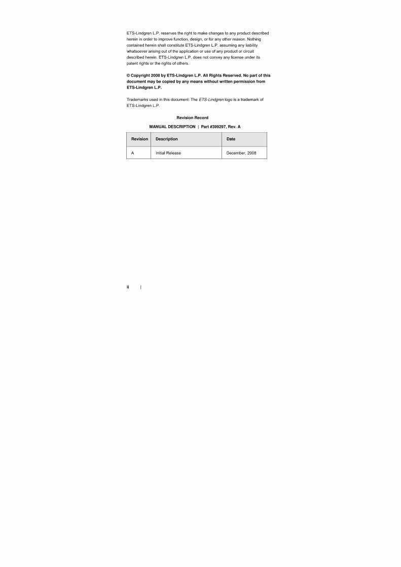
Revision Record
MANUAL DESCRIPTION | Part #399297, Rev. A
Revision Description Date
iii
Table of Contents
Notes, Cautions, and Warnings .............................................. vii
1.0 Introduction .......................................................................... 9
2.0 Maintenance ....................................................................... 11
3.0 Specifications ..................................................................... 13
iv
4.0 Principles of Operation ..................................................... 29
5.0 Assembly and Installation ................................................ 37
6.0 Operation ............................................................................ 41
7.0 Typical Data ........................................................................ 47
v
Appendix A: Warranty ............................................................. 57

vi
vii
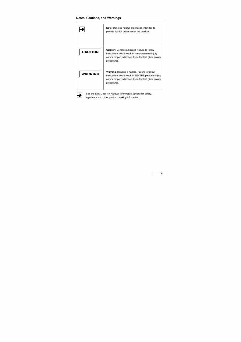
Notes, Cautions, and Warnings
Note:
Caution
Warning
Product Information Bulletin

viii
9
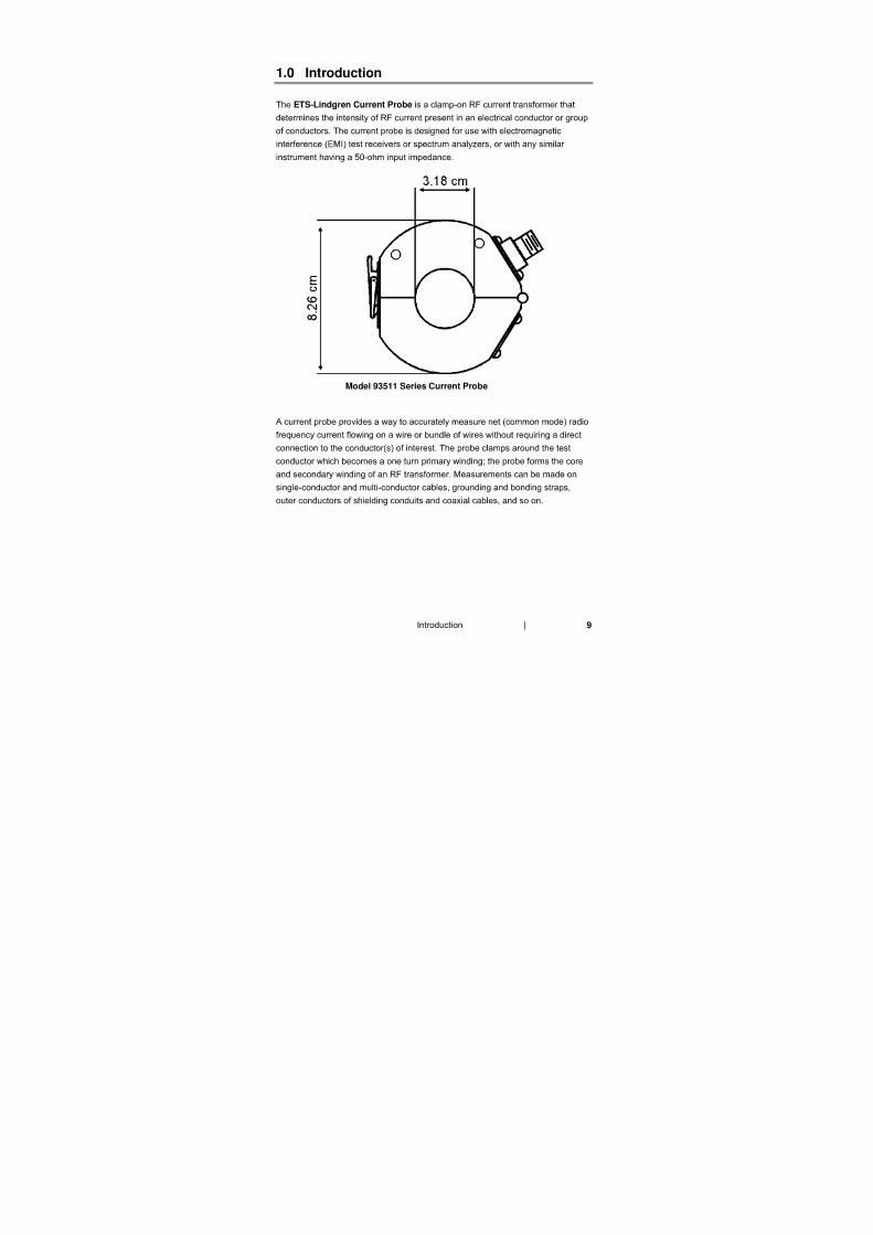
1.0 Introduction
ETS-Lindgren Current Probe
Model 93511 Series Current Probe
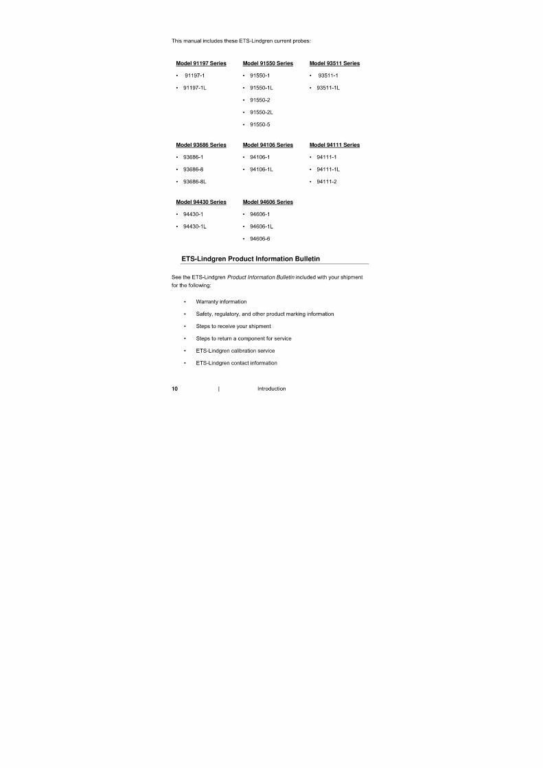
10
Model 91197 Series
•
•
Model 91550 Series
•
•
•
•
•
Model 93511 Series
•
•
Model 93686 Series
•
•
•
Model 94106 Series
•
•
Model 94111 Series
•
•
•
Model 94430 Series
•
•
Model 94606 Series
•
•
•
ETS-Lindgren Product Information Bulletin
Product Information Bulletin
•
•
•
•
•
•
11
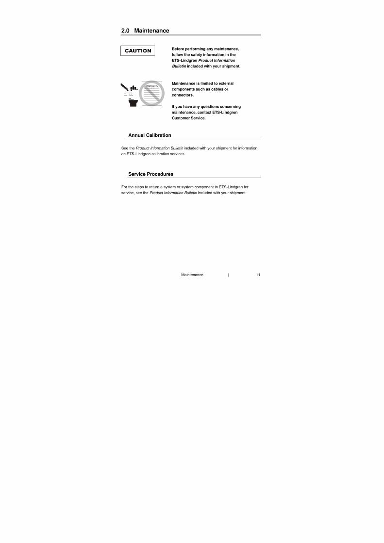
2.0 Maintenance
Before performing any maintenance,
follow the safety information in the
ETS-Lindgren Product Information
Bulletin included with your shipment.
Maintenance is limited to external
components such as cables or
connectors.
If you have any questions concerning
maintenance, contact ETS-Lindgren
Customer Service.
Annual Calibration
Product Information Bulletin
Service Procedures
Product Information Bulletin
WARRANTY

12
13
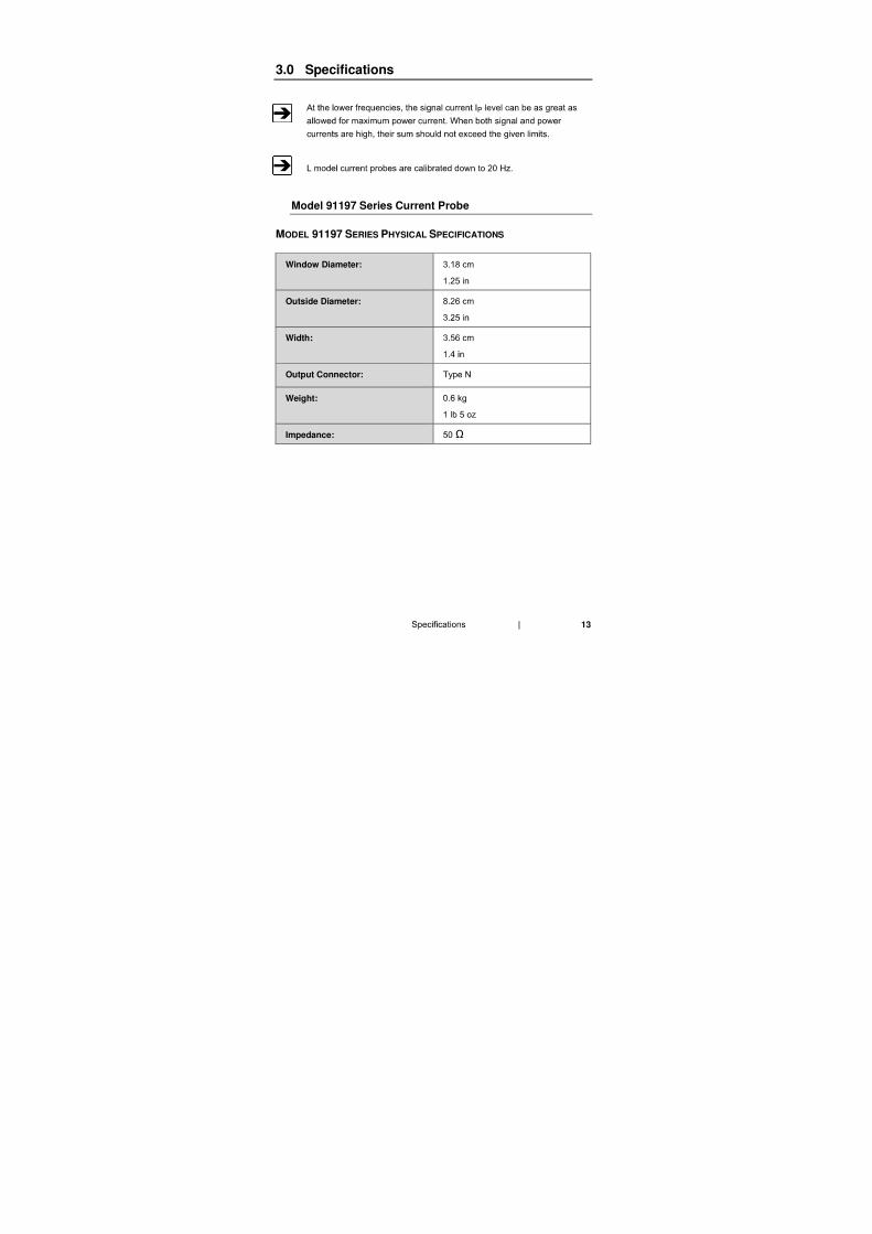
3.0 Specifications
Model 91197 Series Current Probe
MODEL 91197 SERIES PHYSICAL SPECIFICATIONS
Window Diameter:
Outside Diameter:
Width:
Output Connector:
Weight:
Impedance: Ω
14
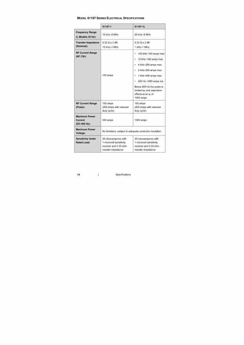
MODEL 91197 SERIES ELECTRICAL SPECIFICATIONS
91197-1 91197-1L
Frequency Range
(L Models 20 Hz):
Transfer Impedance
(Nominal):
Ω Ω
RF Current Range
(RF CW): •
•
•
•
•
•
RF Current Range
(Pulse):
Maximum Power
Current
(DC-400 Hz):
Maximum Power
Voltage:
Sensitivity Under
Rated Load:
15
Model 91550 Series Current Probe
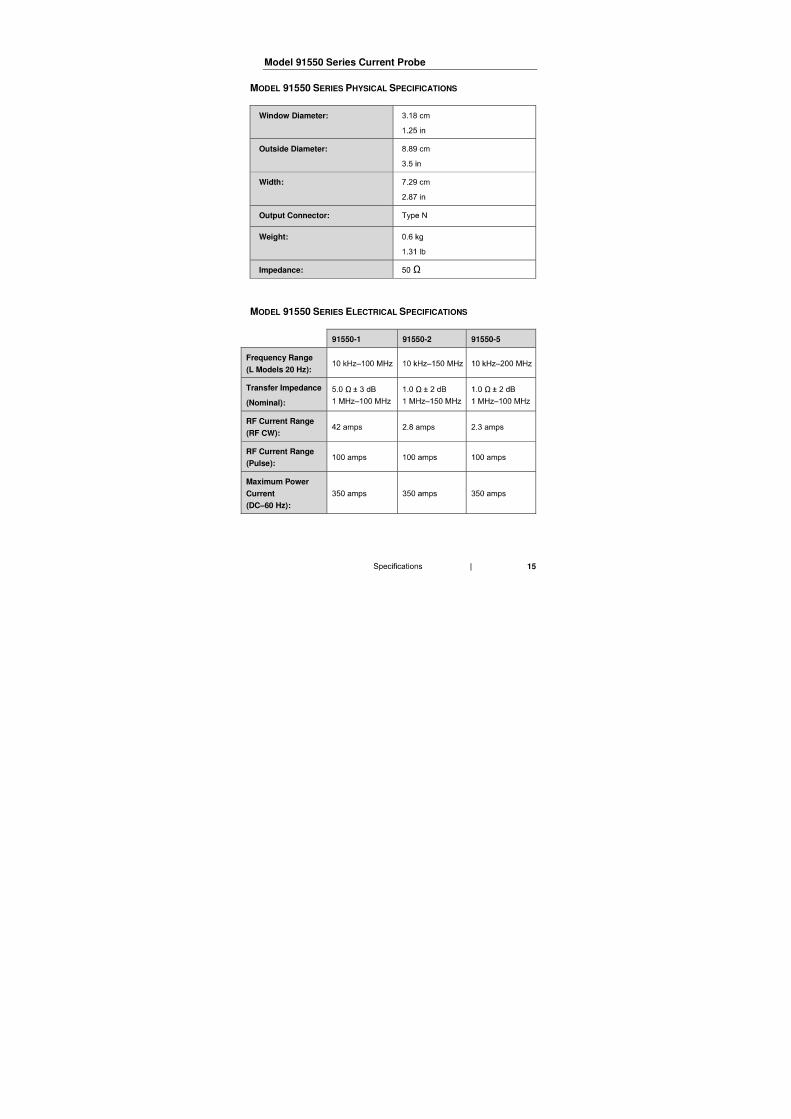
MODEL 91550 SERIES PHYSICAL SPECIFICATIONS
Window Diameter:
Outside Diameter:
Width:
Output Connector:
Weight:
Impedance: Ω
MODEL 91550 SERIES ELECTRICAL SPECIFICATIONS
91550-1 91550-2 91550-5
Frequency Range
(L Models 20 Hz):
Transfer Impedance
(Nominal):
Ω Ω Ω
RF Current Range
(RF CW):
RF Current Range
(Pulse):
Maximum Power
Current
(DC–60 Hz):
16
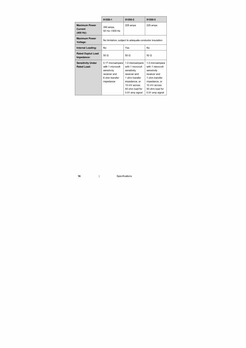
91550-1 91550-2 91550-5
Maximum Power
Current
(400 Hz):
Maximum Power
Voltage:
Internal Loading:
Rated Ouptut Load
Impedance: Ω Ω Ω
Sensitivity Under
Rated Load:
17
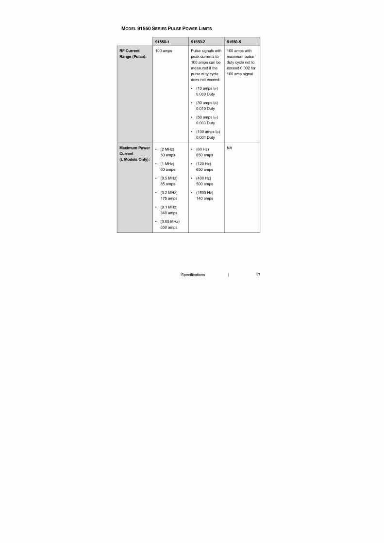
MODEL 91550 SERIES PULSE POWER LIMITS
91550-1 91550-2 91550-5
RF Current
Range (Pulse):
•
•
•
•
Maximum Power
Current
(L Models Only):
•
•
•
•
•
•
•
•
•
•
18
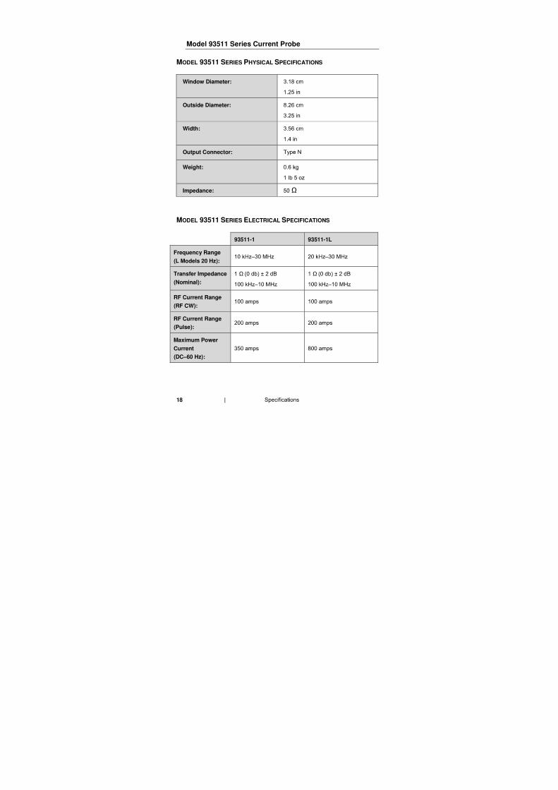
Model 93511 Series Current Probe
MODEL 93511 SERIES PHYSICAL SPECIFICATIONS
Window Diameter:
Outside Diameter:
Width:
Output Connector:
Weight:
Impedance: Ω
MODEL 93511 SERIES ELECTRICAL SPECIFICATIONS
93511-1 93511-1L
Frequency Range
(L Models 20 Hz):
Transfer Impedance
(Nominal):
Ω Ω
RF Current Range
(RF CW):
RF Current Range
(Pulse):
Maximum Power
Current
(DC–60 Hz):
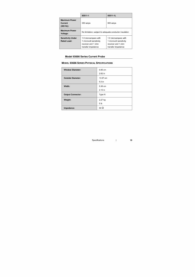
19
93511-1 93511-1L
Maximum Power
Current
(400 Hz):
Maximum Power
Voltage:
Sensitivity Under
Rated Load:
Model 93686 Series Current Probe
MODEL 93686 SERIES PHYSICAL SPECIFICATIONS
Window Diameter:
Outside Diameter:
Width:
Output Connector:
Weight:
Impedance: Ω
20
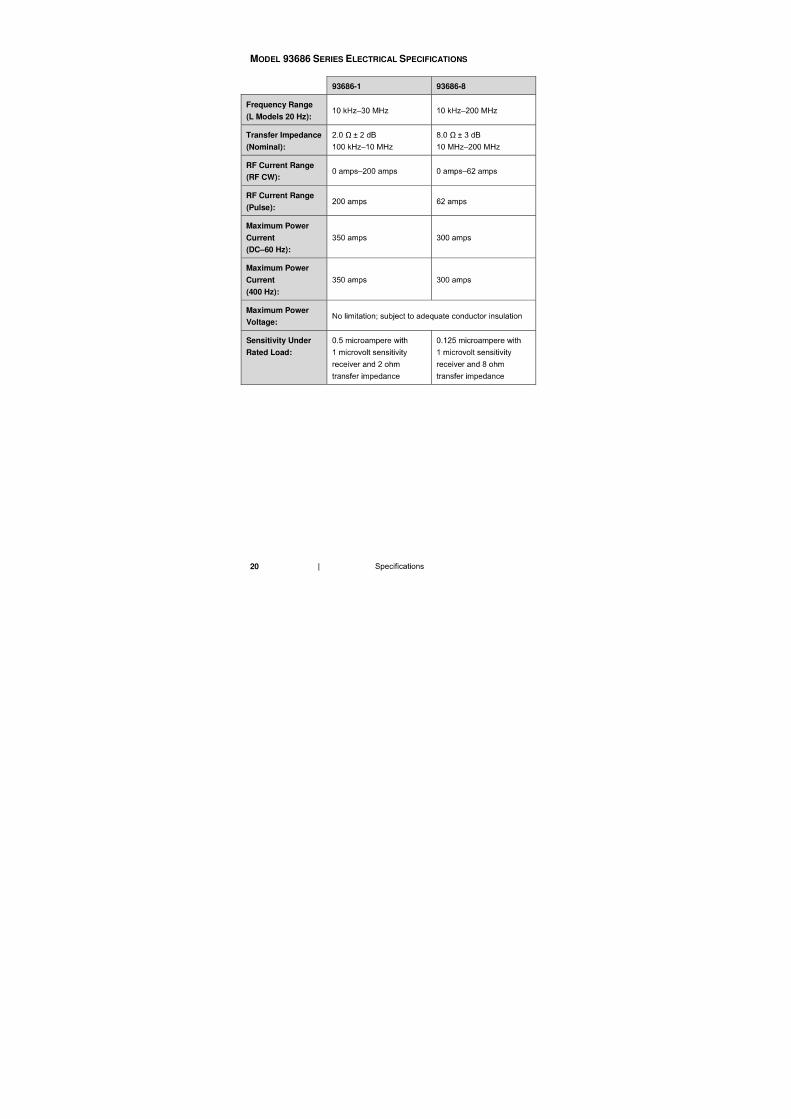
MODEL 93686 SERIES ELECTRICAL SPECIFICATIONS
93686-1 93686-8
Frequency Range
(L Models 20 Hz):
Transfer Impedance
(Nominal):
Ω Ω
RF Current Range
(RF CW):
RF Current Range
(Pulse):
Maximum Power
Current
(DC–60 Hz):
Maximum Power
Current
(400 Hz):
Maximum Power
Voltage:
Sensitivity Under
Rated Load:
21
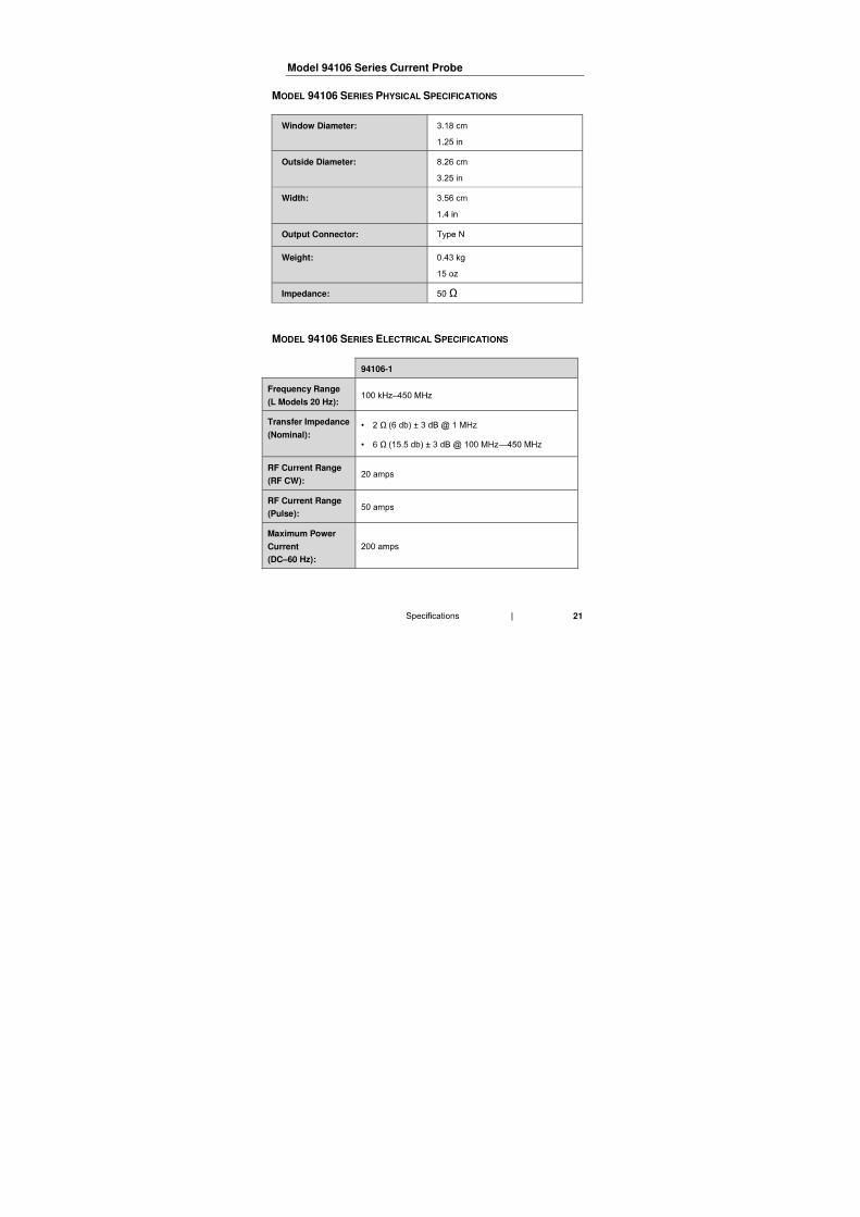
Model 94106 Series Current Probe
MODEL 94106 SERIES PHYSICAL SPECIFICATIONS
Window Diameter:
Outside Diameter:
Width:
Output Connector:
Weight:
Impedance: Ω
MODEL 94106 SERIES ELECTRICAL SPECIFICATIONS
94106-1
Frequency Range
(L Models 20 Hz):
Transfer Impedance
(Nominal): • Ω
• Ω
RF Current Range
(RF CW):
RF Current Range
(Pulse):
Maximum Power
Current
(DC–60 Hz):
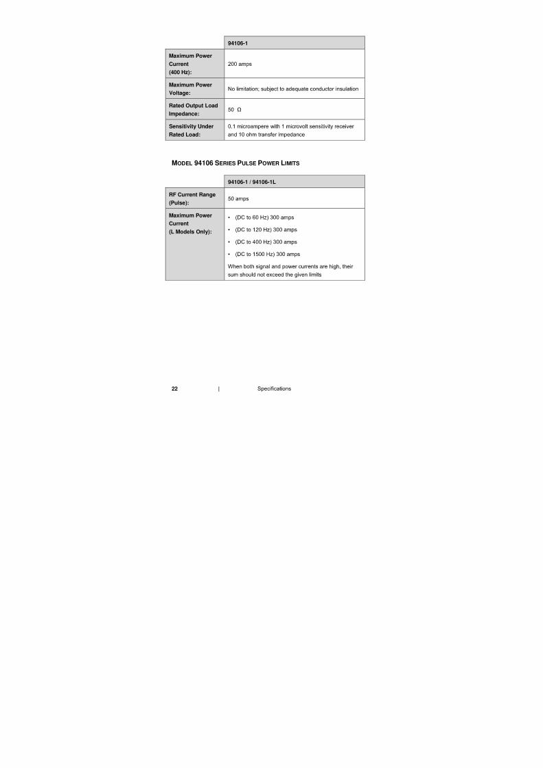
22
94106-1
Maximum Power
Current
(400 Hz):
Maximum Power
Voltage:
Rated Output Load
Impedance: Ω
Sensitivity Under
Rated Load:
MODEL 94106 SERIES PULSE POWER LIMITS
94106-1 / 94106-1L
RF Current Range
(Pulse):
Maximum Power
Current
(L Models Only):
•
•
•
•
23
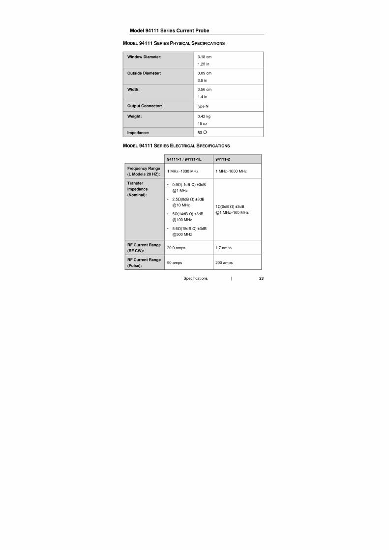
Model 94111 Series Current Probe
MODEL 94111 SERIES PHYSICAL SPECIFICATIONS
Window Diameter:
Outside Diameter:
Width:
Output Connector:
Weight:
Impedance: Ω
MODEL 94111 SERIES ELECTRICAL SPECIFICATIONS
94111-1 / 94111-1L 94111-2
Frequency Range
(L Models 20 HZ):
Transfer
Impedance
(Nominal):
• Ω Ω
• Ω Ω
• Ω Ω
• Ω Ω
Ω Ω
RF Current Range
(RF CW):
RF Current Range
(Pulse):
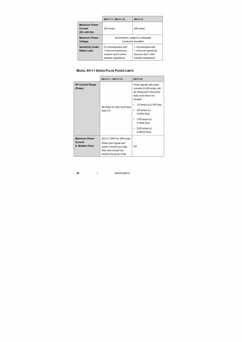
24
94111-1 / 94111-1L 94111-2
Maximum Power
Current
(DC–400 Hz):
Maximum Power
Voltage:
Sensitivity Under
Rated Load:
MODEL 94111 SERIES PULSE POWER LIMITS
94111-1 / 94111-1L 94111-2
RF Current Range
(Pulse):
•
•
•
•
Maximum Power
Current
(L Models Only):
25
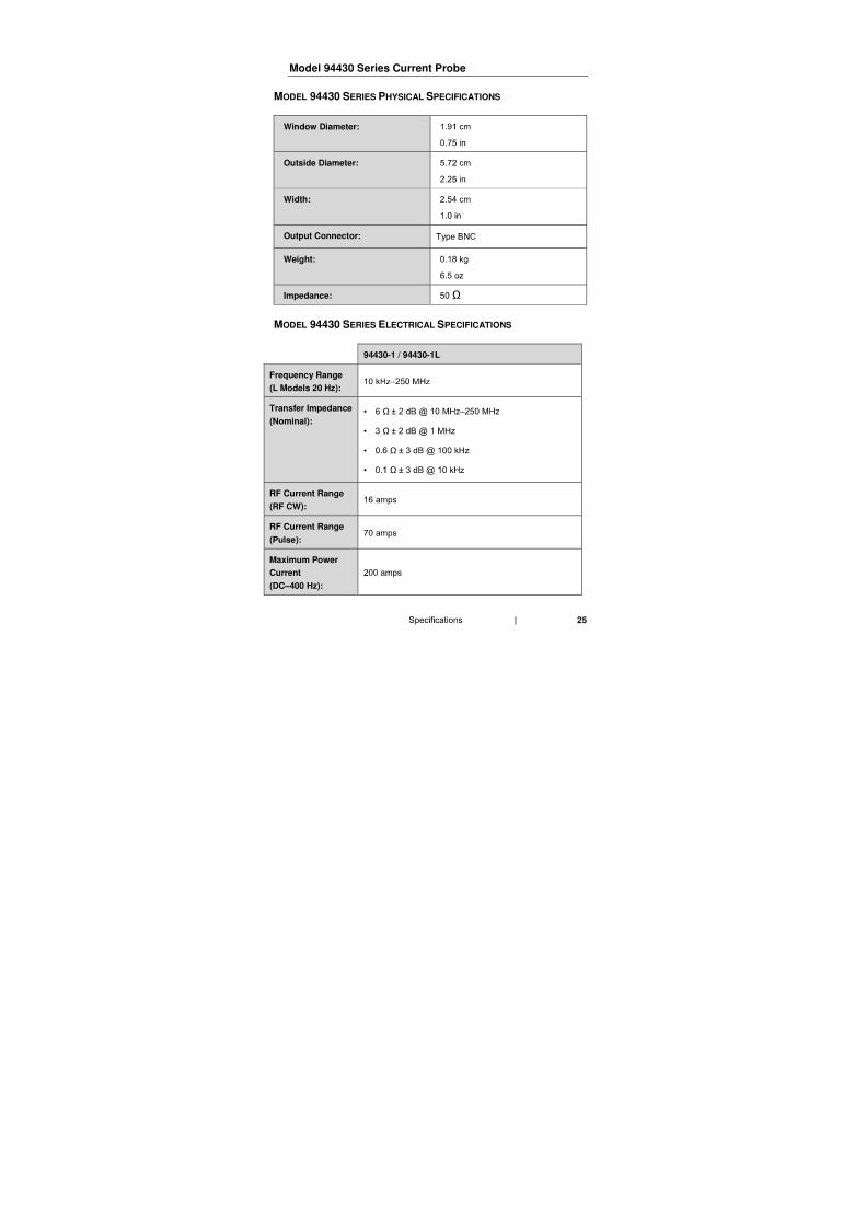
Model 94430 Series Current Probe
MODEL 94430 SERIES PHYSICAL SPECIFICATIONS
Window Diameter:
Outside Diameter:
Width:
Output Connector:
Weight:
Impedance: Ω
MODEL 94430 SERIES ELECTRICAL SPECIFICATIONS
94430-1 / 94430-1L
Frequency Range
(L Models 20 Hz):
Transfer Impedance
(Nominal): • Ω
• Ω
• Ω
• Ω
RF Current Range
(RF CW):
RF Current Range
(Pulse):
Maximum Power
Current
(DC–400 Hz):
26
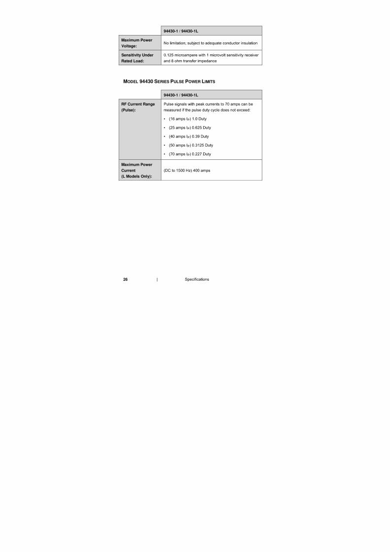
94430-1 / 94430-1L
Maximum Power
Voltage:
Sensitivity Under
Rated Load:
MODEL 94430 SERIES PULSE POWER LIMITS
94430-1 / 94430-1L
RF Current Range
(Pulse):
•
•
•
•
•
Maximum Power
Current
(L Models Only):
27
Model 94606 Series Current Probe
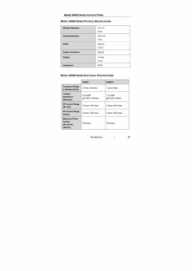
MODEL 94606 SERIES PHYSICAL SPECIFICATIONS
Window Diameter:
Outside Diameter:
Width:
Output Connector:
Weight:
Impedance: Ω
MODEL 94606 SERIES ELECTRICAL SPECIFICATIONS
94606-1 94606-6
Frequency Range
(L Models 20 HZ):
Transfer
Impedance
(Nominal):
Ω Ω
RF Current Range
(RF CW):
RF Current Range
(Pulse):
Maximum Power
Current
(DC–60 Hz)
(400 Hz):
28
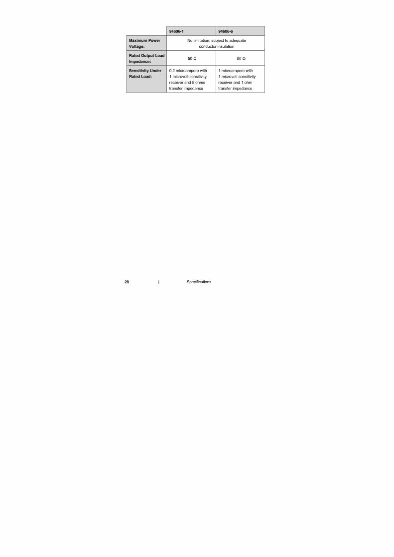
94606-1 94606-6
Maximum Power
Voltage:
Rated Output Load
Impedance: Ω Ω
Sensitivity Under
Rated Load:
29
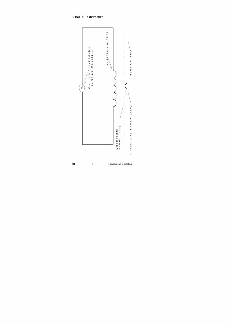
4.0 Principles of Operation
Before connecting any components or
operating the probe, follow the safety
information in the ETS-Lindgren
Product Information Bulletin included with your
shipment.
Circuit
30
BASIC RF TRANSFORMER
31
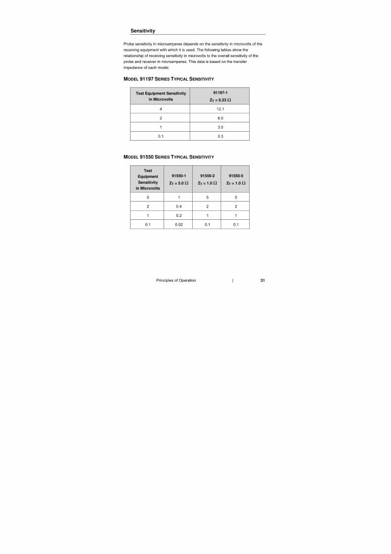
Sensitivity
MODEL 91197 SERIES TYPICAL SENSITIVITY
Test Equipment Sensitivity
in Microvolts
91197-1
ZT = 0.33 Ω
MODEL 91550 SERIES TYPICAL SENSITIVITY
Test
Equipment
Sensitivity
in Microvolts
91550-1
ZT = 5.0 Ω
91550-2
ZT = 1.0 Ω
91550-5
ZT = 1.0 Ω
32
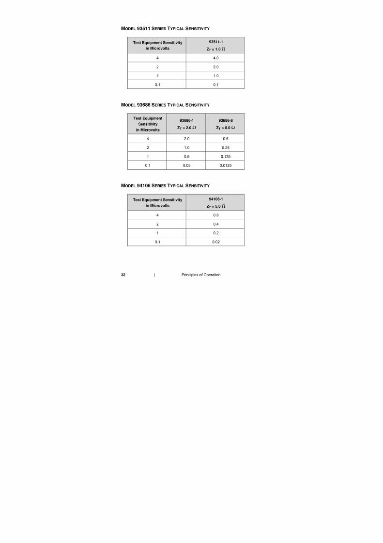
MODEL 93511 SERIES TYPICAL SENSITIVITY
Test Equipment Sensitivity
in Microvolts
93511-1
ZT = 1.0 Ω
MODEL 93686 SERIES TYPICAL SENSITIVITY
Test Equipment
Sensitivity
in Microvolts
93686-1
ZT = 2.0 Ω
93686-8
ZT = 8.0 Ω
MODEL 94106 SERIES TYPICAL SENSITIVITY
Test Equipment Sensitivity
in Microvolts
94106-1
ZT = 5.0 Ω
33
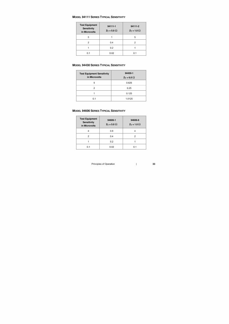
MODEL 94111 SERIES TYPICAL SENSITIVITY
Test Equipment
Sensitivity
in Microvolts
94111-1
ZT = 5.0 Ω
94111-2
ZT = 1.0 Ω
MODEL 94430 SERIES TYPICAL SENSITIVITY
Test Equipment Sensitivity
in Microvolts
94430-1
ZT = 6.0 Ω
MODEL 94606 SERIES TYPICAL SENSITIVITY
Test Equipment
Sensitivity
in Microvolts
94606-1
ZT = 5.0 Ω
94606-6
ZT = 1.0 Ω
34
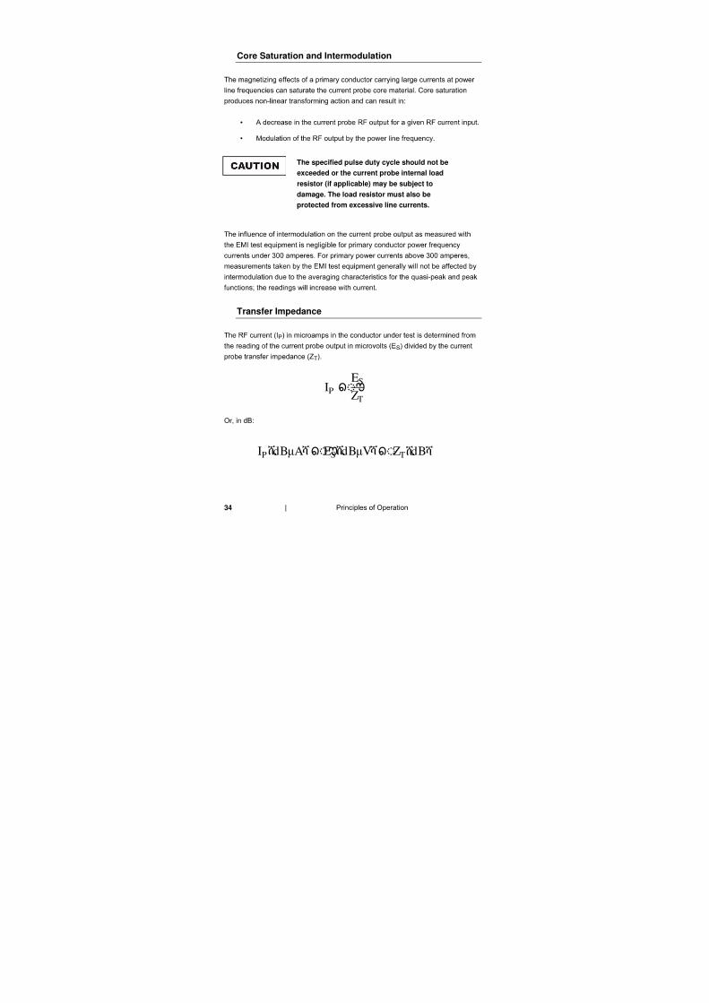
Core Saturation and Intermodulation
•
•
The specified pulse duty cycle should not be
exceeded or the current probe internal load
resistor (if applicable) may be subject to
damage. The load resistor must also be
protected from excessive line currents.
Transfer Impedance
IP ES
ZT
IPሺdBµAሻESሺdBµVሻ ZTሺdBሻ
35
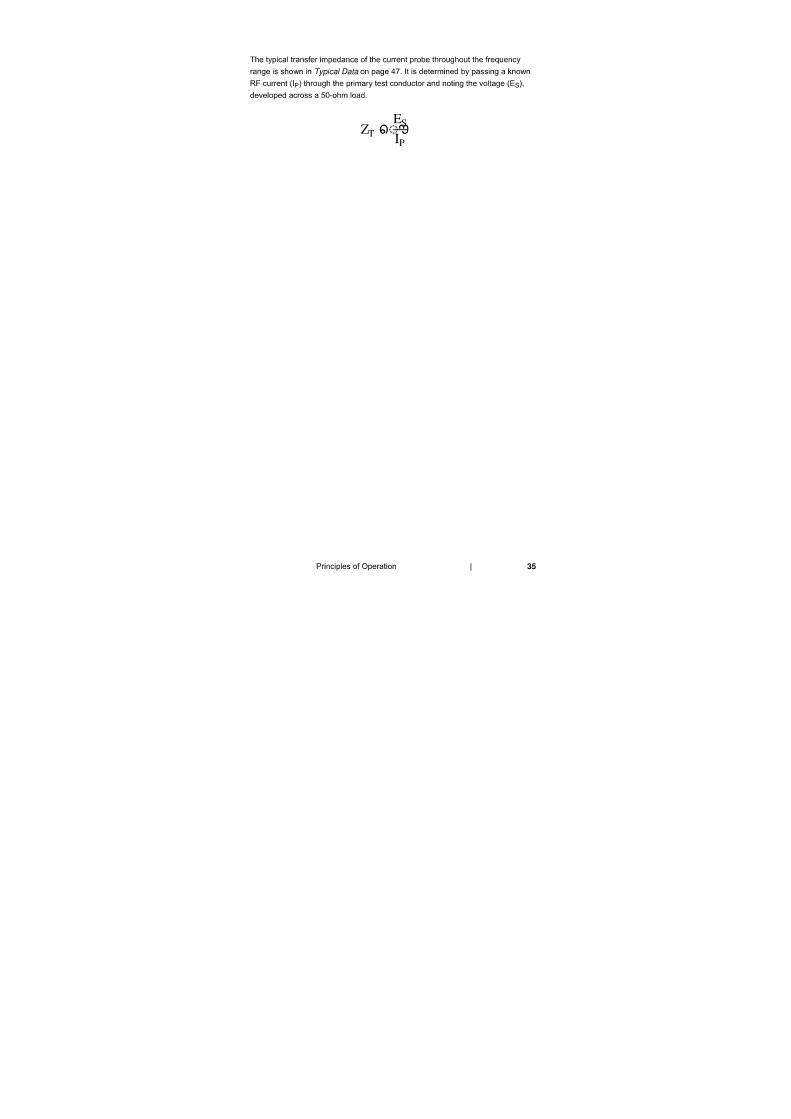
Typical Data
ZT ES
IP

36
37
5.0 Assembly and Installation
Before connecting any components, follow the
safety information in the ETS-Lindgren
Product Information Bulletin included with your
shipment.
Equipment Setup to Measure RF Current
FOR A SINGLE CONDUCTOR
1.
2.
FOR A TWO-CONDUCTOR CABLE
•
•
FOR MULTI-CONDUCTOR CABLES
38
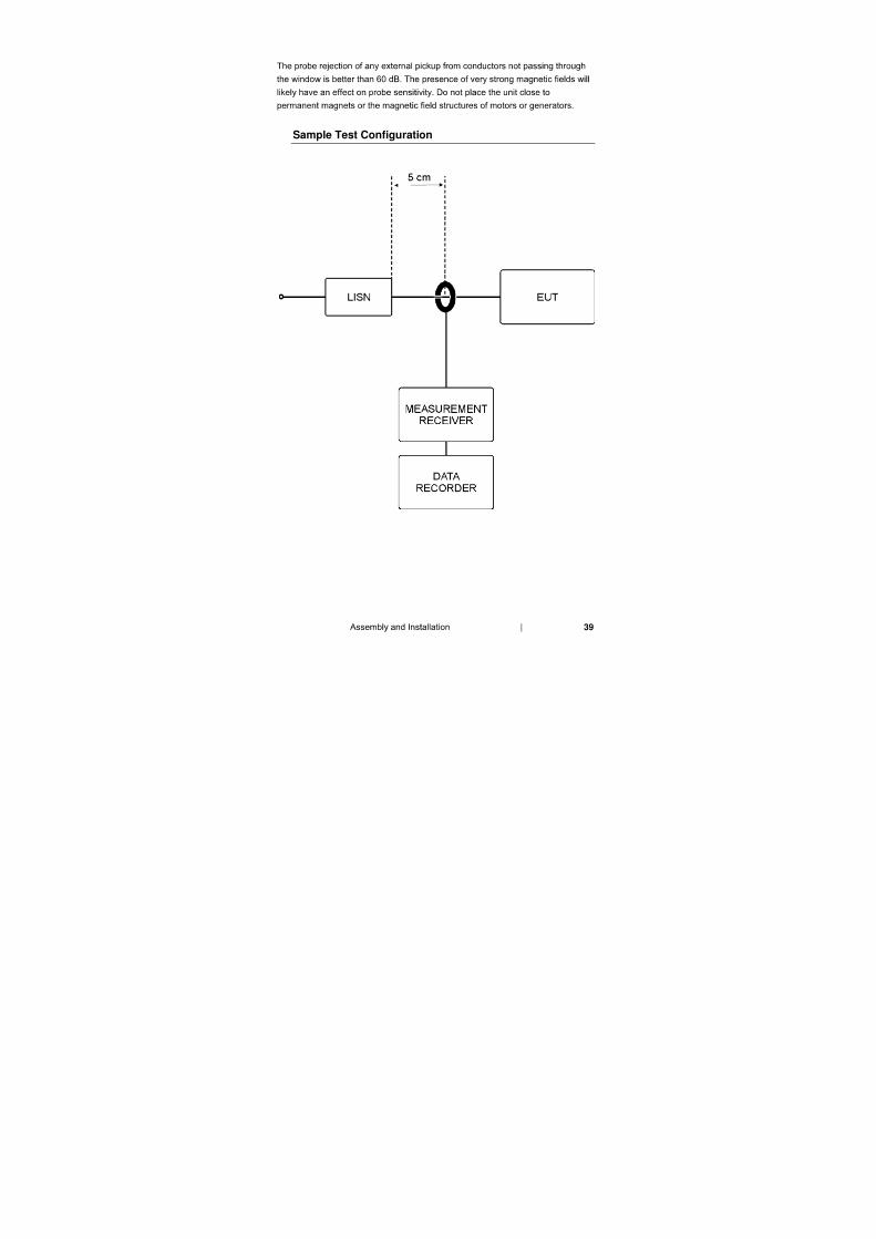
TO EVALUATE SHIELDING EFFECTIVENESS
Installation Instructions
Current Probe Maximum Outside Diameter
39
Sample Test Configuration

40
41
6.0 Operation
Before connecting any components, follow the
safety information in the ETS-Lindgren
Product Information Bulletin included with your
shipment.
If measuring uninsulated conductors: Use
extreme care when installing the current probe
and taking measurements. If possible,
de-energize the test sample during assembly
and disassembly of the setup. Also, arrange to
center the test conductor in the current probe
window for additional voltage breakdown
protection.
Do not permit the uninsulated current probe
connector and cable connectors to come in
contact with the ground plane or other nearby
conductors. This will prevent possible
measurement error due to ground loops, and
will avoid danger from high voltages.
Ensure that the 50-ohm load is capable of safely
dissipating the incurred power. Should the load
become disconnected, the developed voltage
will be come much greater and may be very
dangerous.
42
Signal Measurement
OSCILLOSCOPE USE: IN TERMS OF RF AMPERES
1.
2.
Example:
IN TERMS OF dB ABOVE ONE MICROAMPERE AT METER INPUT
(CW CONDUCTED MEASUREMENTS)
1.
2.
At meter input
43
Example:
IN TERMS OF dB ABOVE ONE MICROAMPERE PER MEGAHERTZ AT
METER INPUT (BROADBAND INTERFERENCE MEASUREMENT)
1.
2.
At meter input
Example:
44
IN TERMS OF MICROAMPERE IN TEST SAMPLE LEAD
(CW CONDUCTED MEASUREMENTS)
1.
2.
Example:
IN TERMS OF MICROAMPERE PER MEGAHERTZ IN TEST SAMPLE LEAD
(BROADBAND INTERFERENCE MEASUREMENT)
1.
2.
Example:
45
Signal Injection

46
47
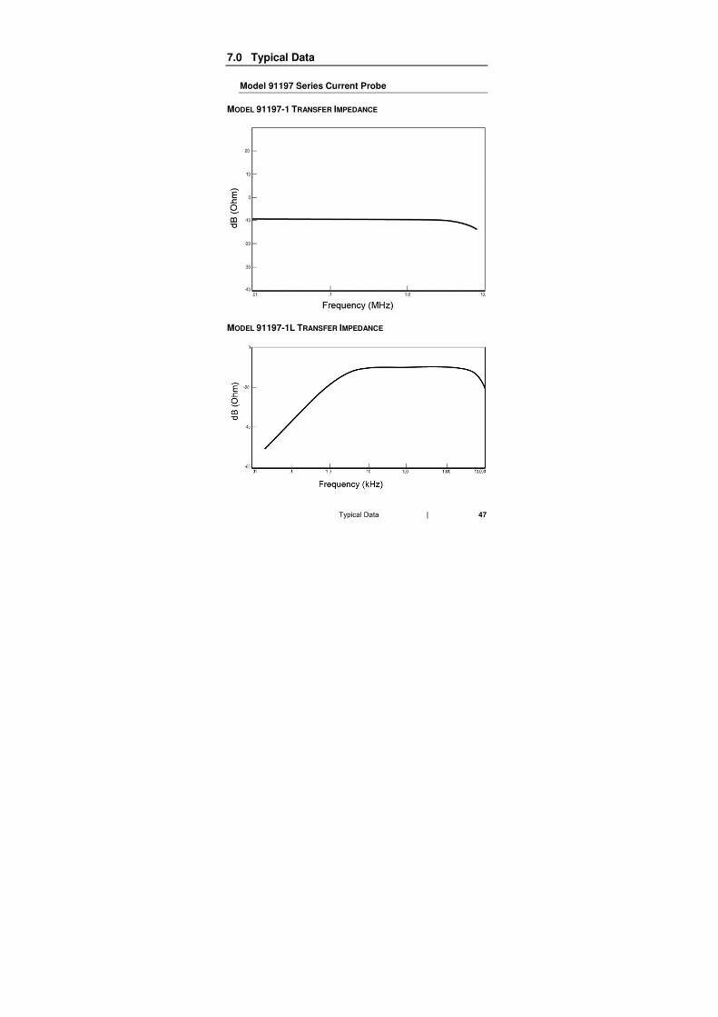
7.0 Typical Data
Model 91197 Series Current Probe
MODEL 91197-1 TRANSFER IMPEDANCE
MODEL 91197-1L TRANSFER IMPEDANCE
48
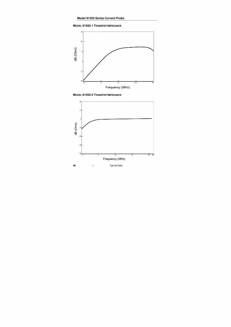
Model 91550 Series Current Probe
MODEL 91550-1 TRANSFER IMPEDANCE
MODEL 91550-2 TRANSFER IMPEDANCE
49
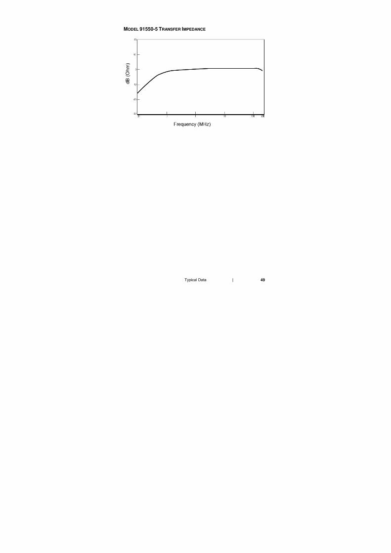
MODEL 91550-5 TRANSFER IMPEDANCE
50
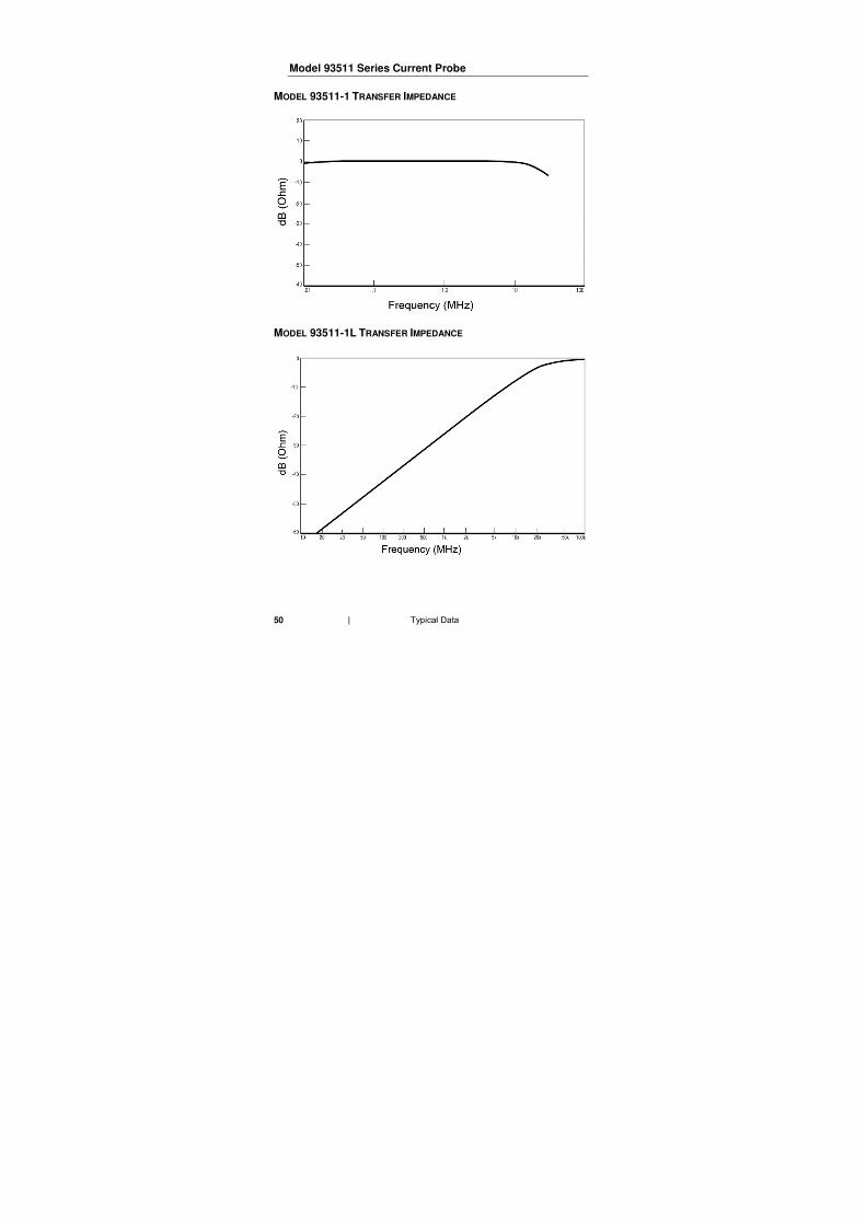
Model 93511 Series Current Probe
MODEL 93511-1 TRANSFER IMPEDANCE
MODEL 93511-1L TRANSFER IMPEDANCE
51
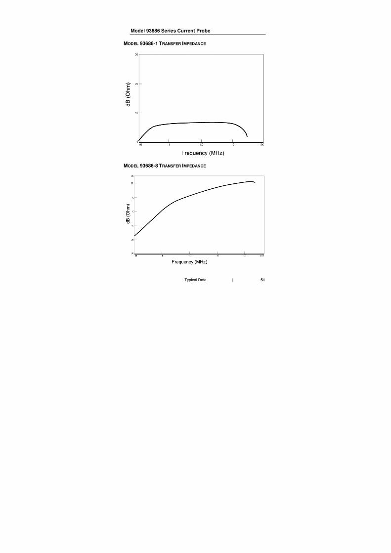
Model 93686 Series Current Probe
MODEL 93686-1 TRANSFER IMPEDANCE
MODEL 93686-8 TRANSFER IMPEDANCE
52
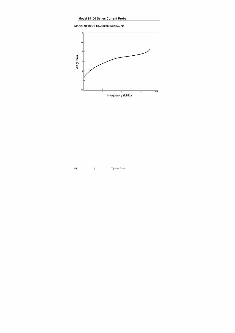
Model 94106 Series Current Probe
MODEL 94106-1 TRANSFER IMPEDANCE
53
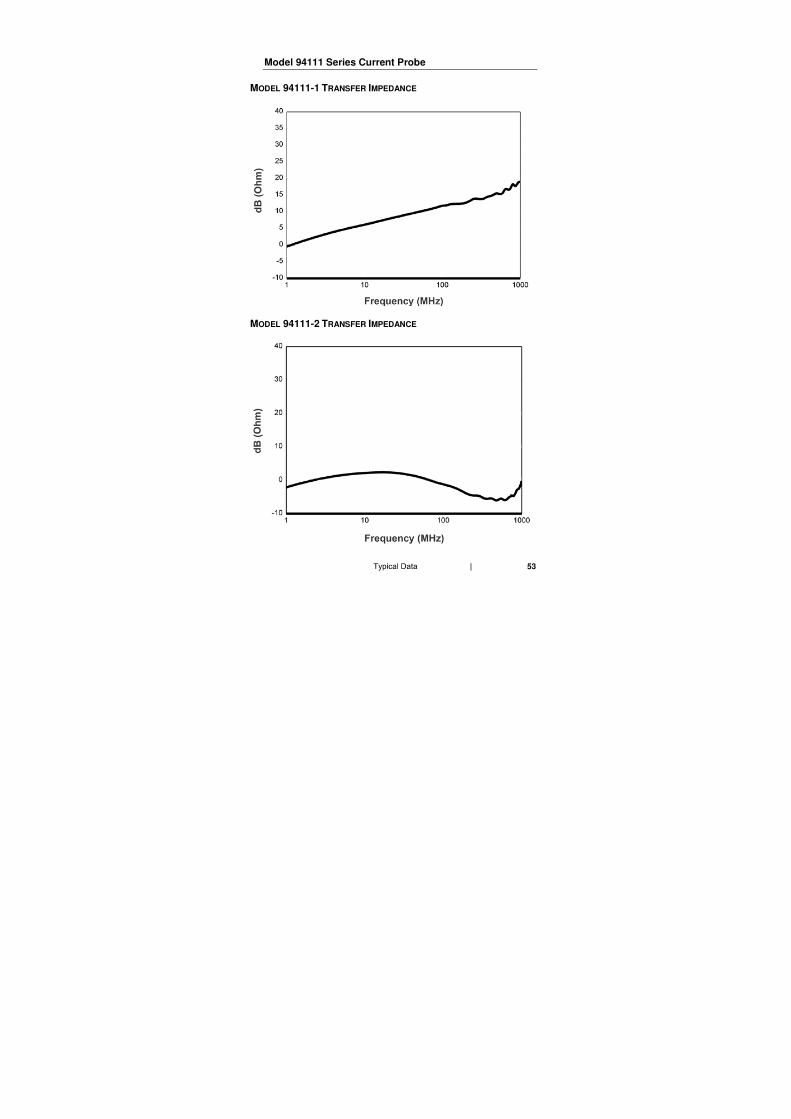
Model 94111 Series Current Probe
MODEL 94111-1 TRANSFER IMPEDANCE
MODEL 94111-2 TRANSFER IMPEDANCE
54
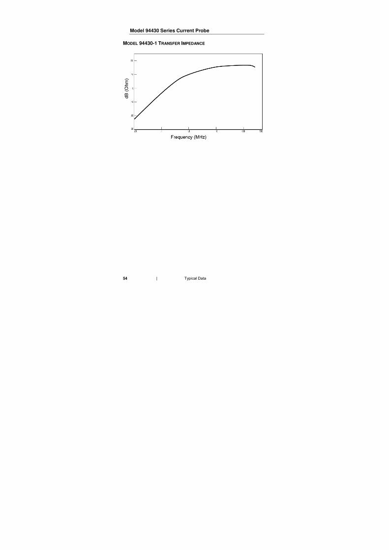
Model 94430 Series Current Probe
MODEL 94430-1 TRANSFER IMPEDANCE
55
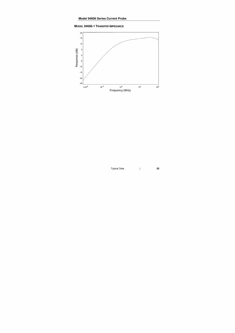
Model 94606 Series Current Probe
MODEL 94606-1 TRANSFER IMPEDANCE

56
57
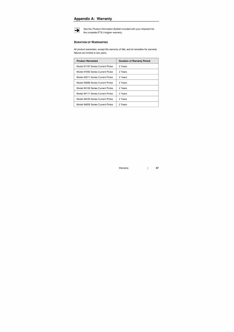
Appendix A: Warranty
Product Information Bulletin
DURATION OF WARRANTIES
Product Warranted Duration of Warranty Period