Current Mode Converter Shen-Yaur Chen. Limited value of error voltage provides peak current...
59
Current Mode Converter Shen-Yaur Chen
-
Upload
francis-mills -
Category
Documents
-
view
217 -
download
2
Transcript of Current Mode Converter Shen-Yaur Chen. Limited value of error voltage provides peak current...

Current Mode Converter
Shen-Yaur Chen

• Limited value of error voltage provides peak current protection
• No Soft-start mechanism is required
• Modules share a common error voltage
• Peak Current in each is kept the same
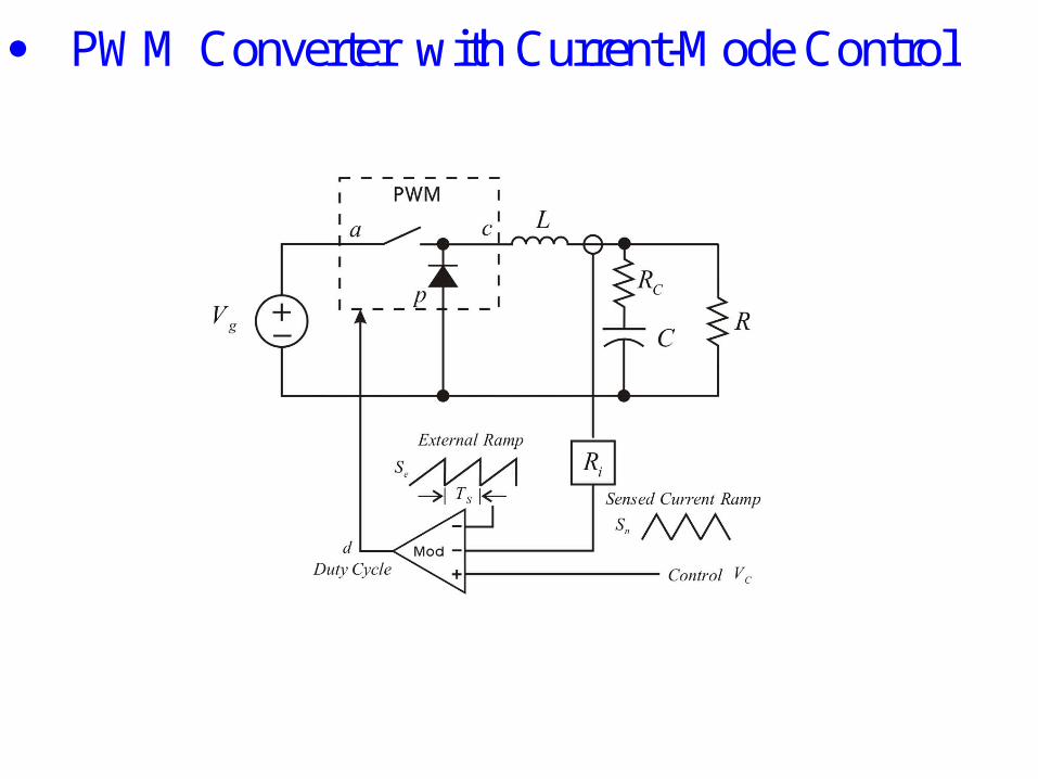
PWM Converter with Current-Mode Control

PWM Switch Model

• Limited value of error voltage provides peak current protection
• No Soft-start mechanism is required
• Modules share a common error voltage
• Peak Current in each is kept the same

2
1
m D
m D
2
11
O O
m DI I I
m D
n
n O
DI I
D
Subharmonic
0.5 UnstableD
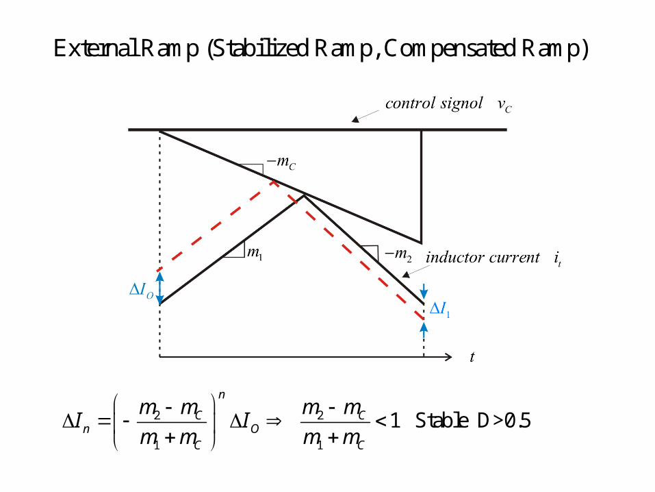
External Ramp (Stabilized Ramp, Compensated Ramp)
2 2
1 1
1 Stable D>0.5n
C Cn O
C C
m m m mI I
m m m m

Average Model
• R. D. Middlebrook, “Topics in Multiple-Loop Regulations and Current-Mode Programming,” in proc. IEEE Power Electron. Spec. Conf., Rec., 1985, pp. 716-732.
1 2
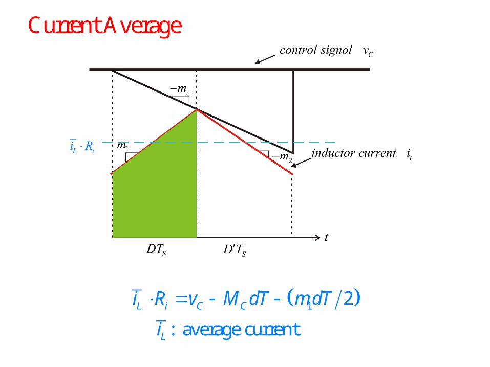
: average current
L i C C
L
i R v M dT m dT
i
Current Average
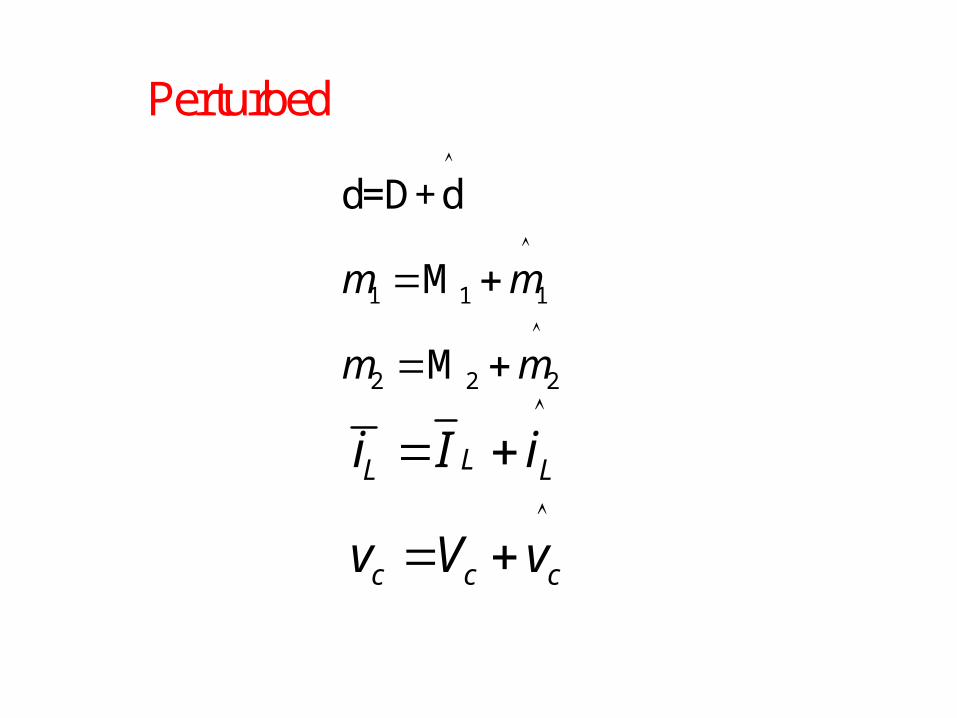
Perturbed
1 1 1
2 2 2
d=D+d
M
M
m m
m m
LL L
c c c
i I i
v V v
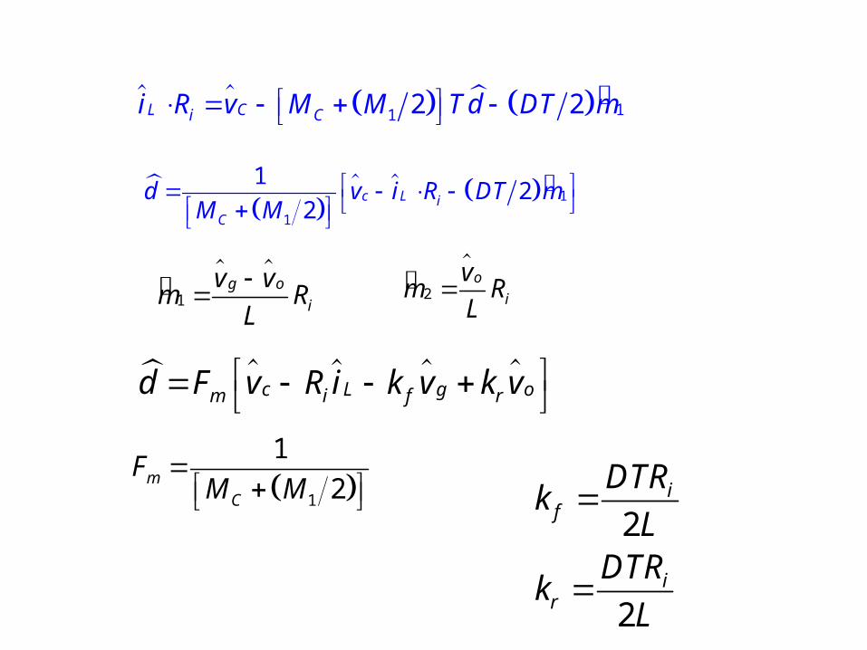
11 2 2L Ci Ci R v M M T d DT m
1
g o
i
v vm R
L
2
o
i
vm R
L
c L g om i f rd F v R i k v k v
1
1
12
2c L i
C
d v i R DT mM M
1
1
2mC
FM M
2
2
if
ir
DTRk
LDTR
kL
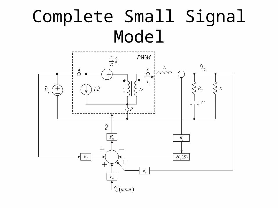
Complete Small Signal Model

Exact Average
• G. C. Verghese, C. A. Bruzos, and K. N. Mahabir, “Averaged and Sampled-Data Models for PCM Control: A Reexamination,” in proc. IEEE Power Electron. Spec. Conf., Rec., 1989, pp. 3-13.

Exact Average
1 22 2L i C Ci R v M dT d m dT d m dT

2 21 22 2L Ci Ci R v M T d D T m D T m
2 21 2
12 2c L i
C
d v i R D T m D T mM T
1
g o
i
v vm R
L
2
o
i
vm R
L
2
2
1 22
1
f i
ir
mc
Dk TR
LTR
k DL
Fm T

Ridley’s Model
• R. B. Ridley, A New small-signal Model for Current-Mode Control, Ridley Engineering, Inc.,July 1999.

Ridley's Model
Current Programmed Converter
Peak Current Mode Converter
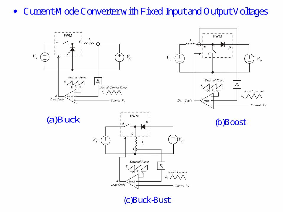
Current-Mode Converter with Fixed Input and Output Voltages
(a)Buck (b)Boost
(c)Buck-Bust

Generic Current-Mode Cell

PWM Switch Model

Small-Signal Model of the Current-mode Cell with Fixed Voltage
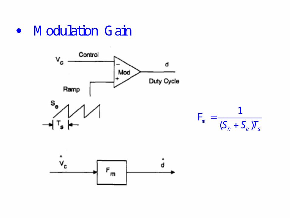
Modulation Gain
m
1 F
( )n e sS S T
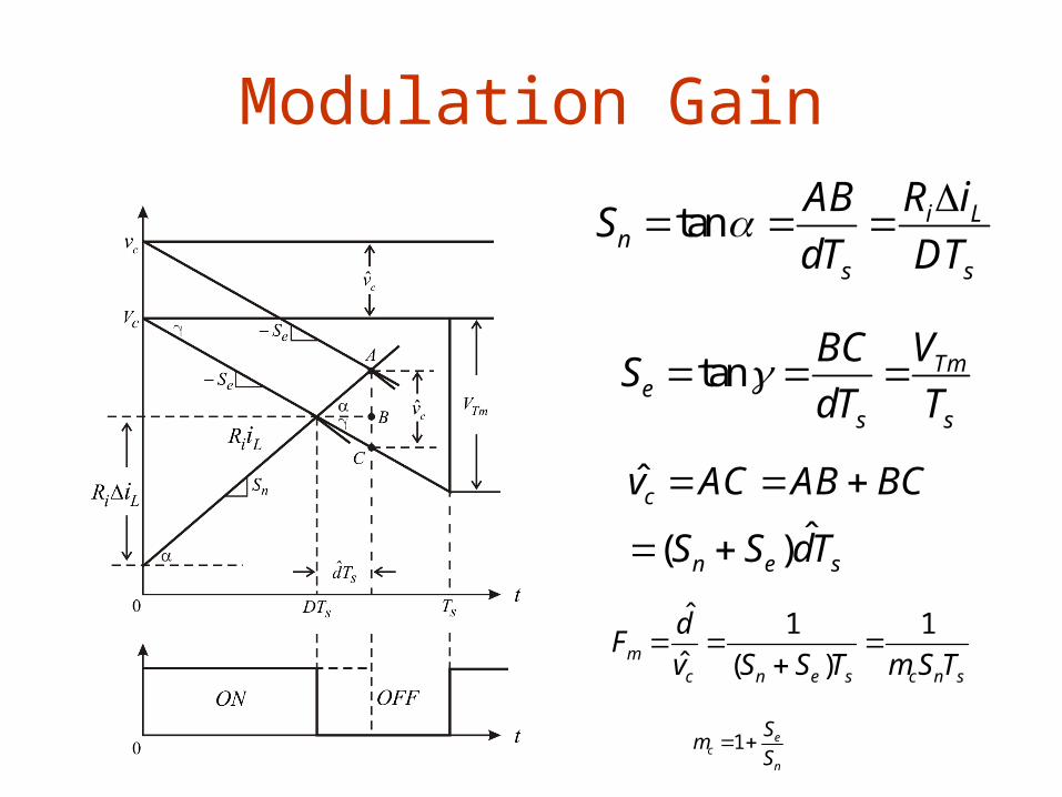
Modulation Gain
tan i Ln
s s
AB R iS
dT DT
tan Tme
s s
BC VS
dT T
ˆ
ˆ( )
c
n e s
v AC AB BC
S S dT
ˆ 1 1ˆ ( )m
c n e s c n s
dF
v S S T m S T
1 ec
n
Sm
S
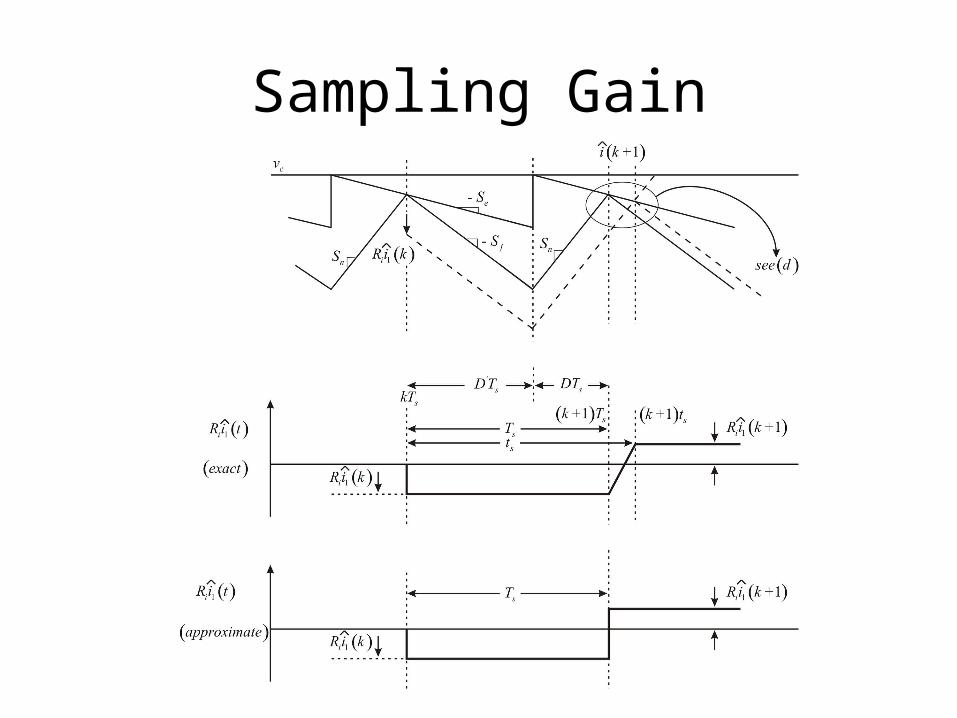
Sampling Gain
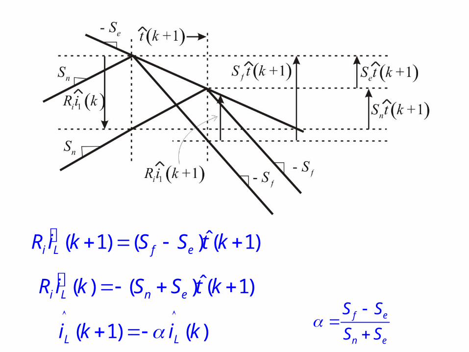
ˆ( 1) ( ) ( 1)i L f eR i k S S t k
ˆ( ) ( ) ( 1)i L n eR i k S S t k
( 1) ( )L Li k i k
f e
n e
S S
S S

1 ( 1) (1 ) ( 1)L c
i
i k v kR
Control Perturbation
k k +1
ˆ( )si n
t
(exact)
(b)
Sn Sf
Se
ˆ( )si k
(a)
ˆc cV v
(c)
k
ˆ( )si n
t
(approx)
k +1

Discret Time Response
1 ( 1) ( ) (1 ) ( 1)L L c
i
i k i k v kR
Subharmonics oscilla n tio1 Oscillation
f
n
Without external Ramp
S
= 1S
Cycle D 0.5Duty

( ) 1( ) (1 )
( )L
ic
i z zH z
R zv z
SystemSample and Hold
1 F(s)=H(e ) (1 e )
1 1 e 1 =
e
s s
s
s
sT sT
s
sT
sTi s
sT
R sT
z Transform

i
f
ii
( ) F ( )
( )
S
1 F ( )
ap ac cpL
i cpi acn
n f
V V Vi ss
sL sLd s
RVRVS
L LS S
sR s
m
1
1 1
( )
F
( )
n e s
m ii s
F F sR
S
s
T
T
S
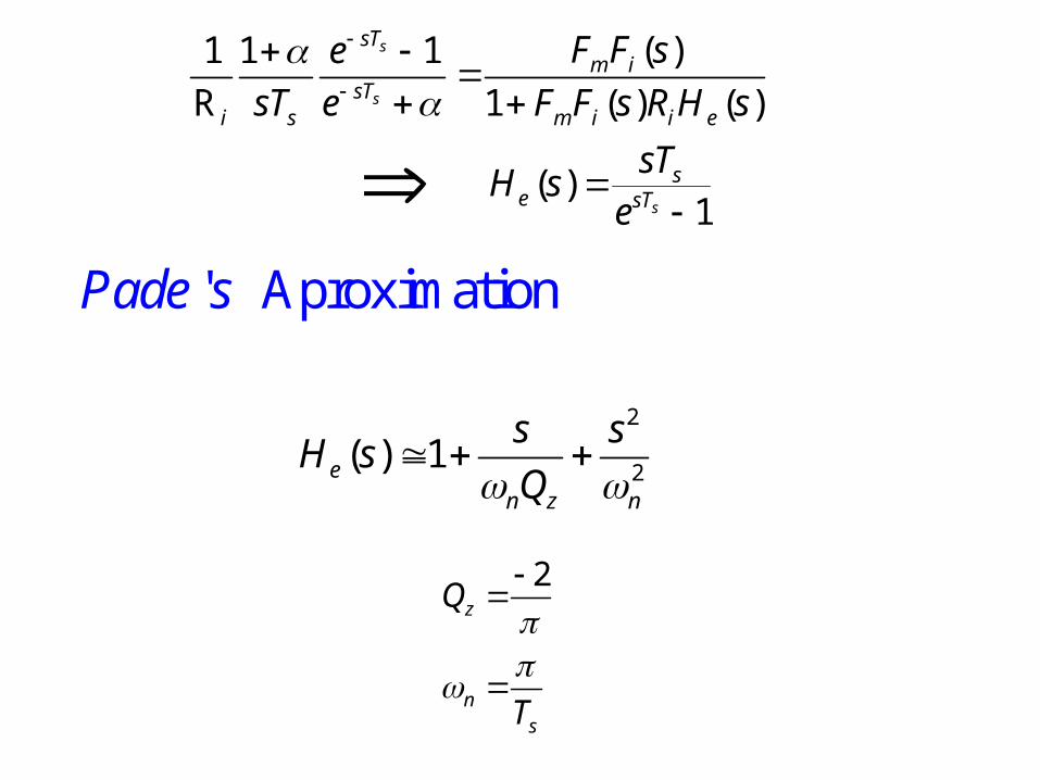
( )1 1 1
R 1 ( ) ( )
( )1
s
s
s
sTm i
sTi s m i i e
se sT
F F se
sT e F F s R H s
sTH s
e
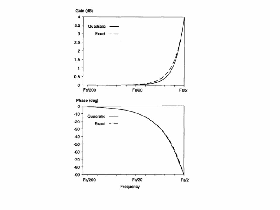
' Aproximation
Pade s
2
2( ) 1e
n z n
s sH s
Q
2z
ns
Q
T

Complete Small-Signal Model for Current-Mode Control
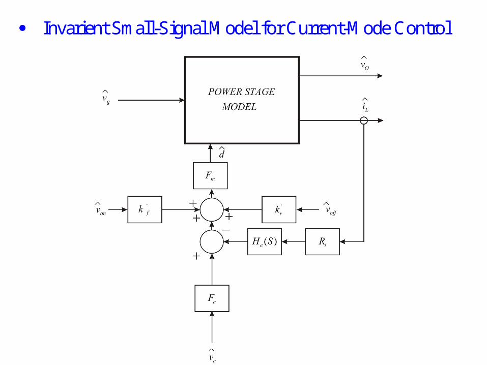
Invarient Small-Signal Model for Current-Mode Control
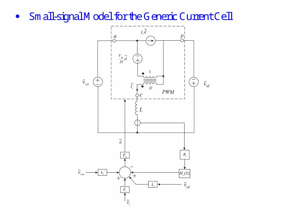
Small-signal Model for the Generic Current Cell

Generic Current Cell with Fixed Voltage During Off-Time

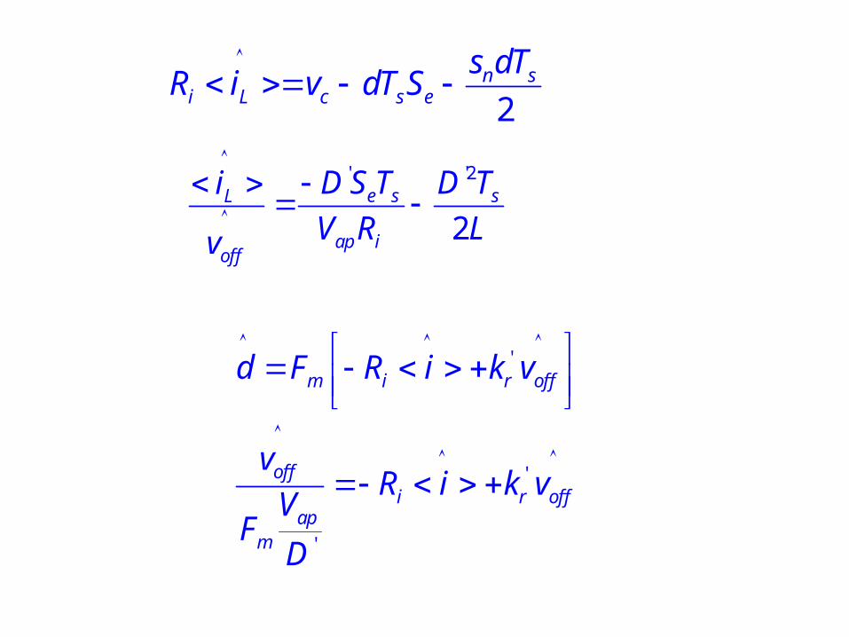
'
2f s
i L c s e
s d TR i v dT S
'
off
on off
on
on off
vd
v v
vd
v v
2
2e s sL
ap ion
DS T D Ti
V R Lv
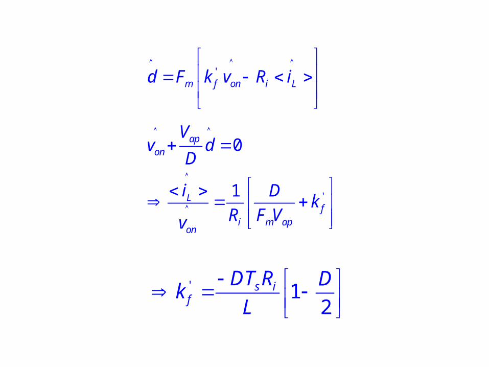
'
'
0
1
m f on i L
apon
Lf
i m apon
d F k v R i
Vv d
D
i Dk
R F Vv
' 12
s if
DT R Dk
L
2n s
i L c s e
s dTR i v dT S
' '2
2e s sL
ap ioff
D S T D Ti
V R Lv
'
'
'
m i r off
offi r off
apm
d F R i k v
vR i k v
VF
D
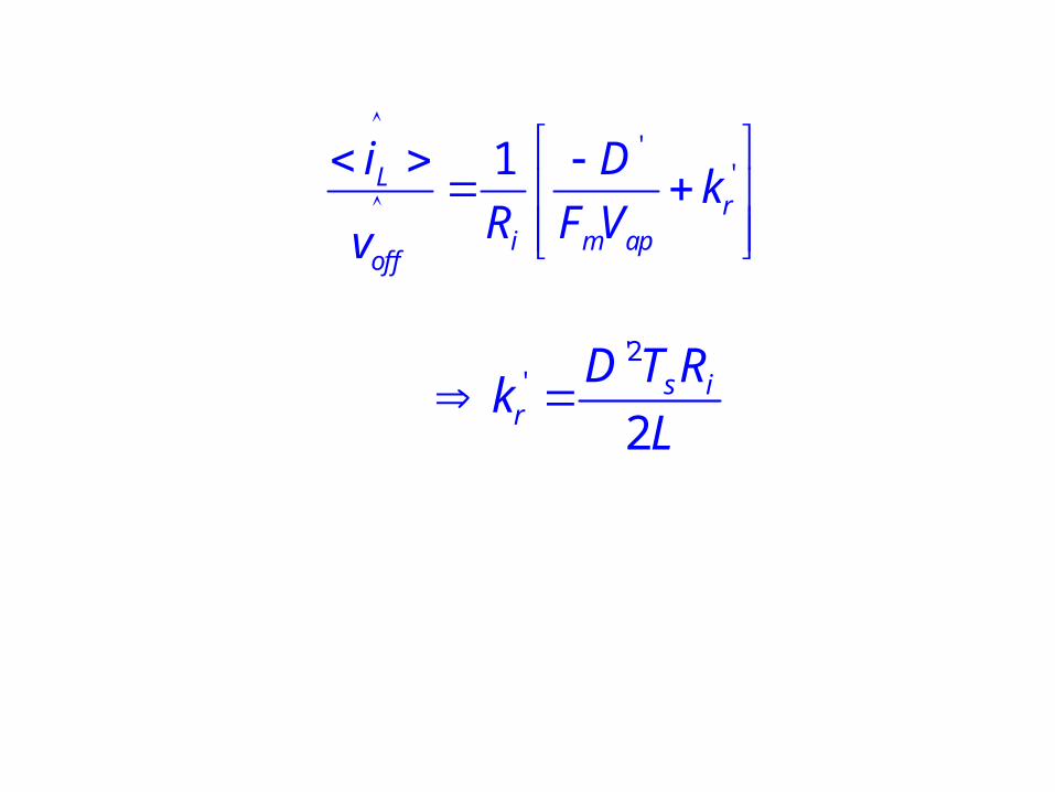
''1Lr
i m apoff
i Dk
R F Vv
'2'
2s i
r
D T Rk
L
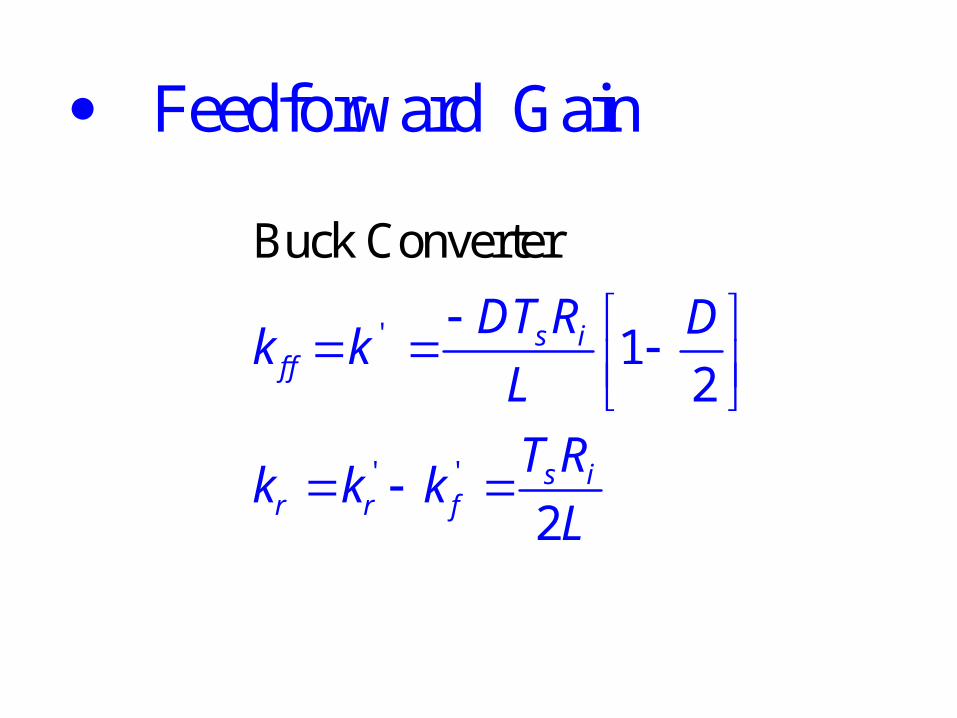
Feedforward Gain
'
' '
Buck Converter
12
2
s if f
s ir r f
DT R Dk k
L
T Rk k k
L
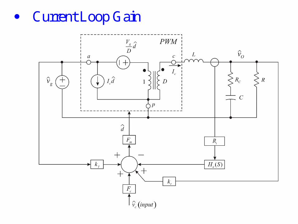
Current Loop Gain
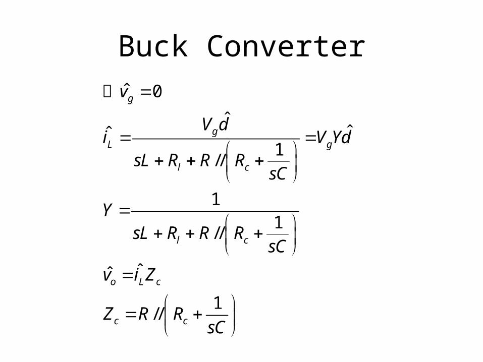
Buck Converterˆ 0
ˆˆˆ
1//
11
//
ˆˆ
1//
g
gL g
l c
l c
o L c
c c
v
V di V Yd
sL R R RsC
YsL R R R
sC
v i Z
Z R RsC
令
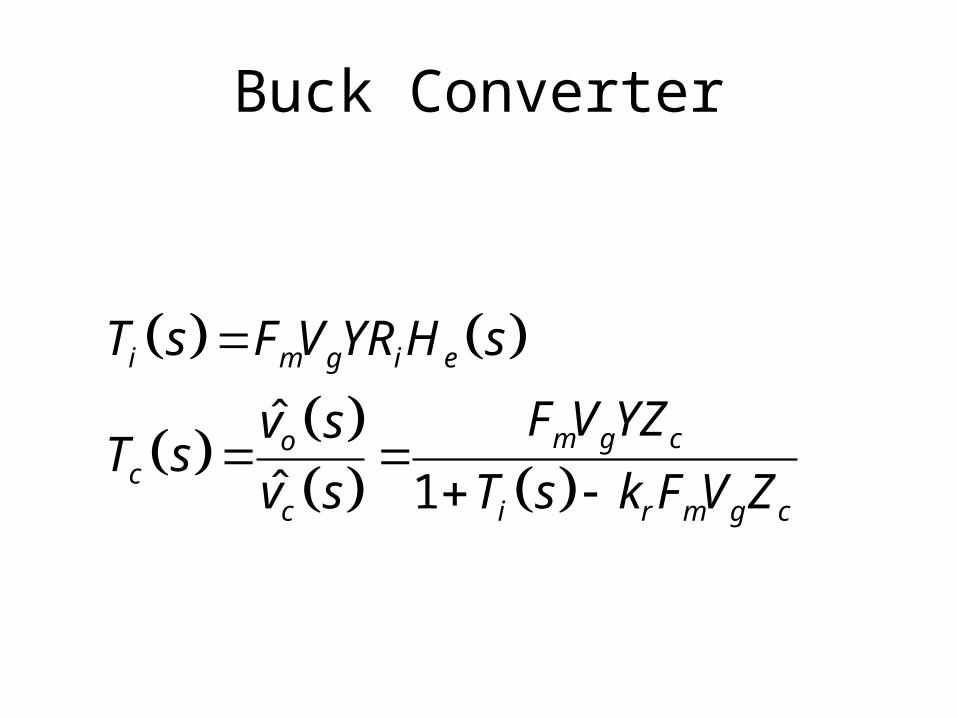
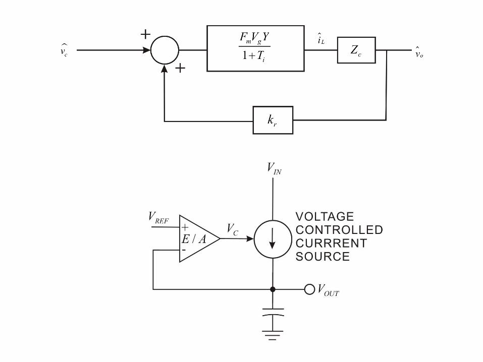
Buck Converter
ˆ
ˆ 1
i m g i e
m g coc
c i r m g c
T s F V YR H s
F V YZv sT s
v s T s k F V Z

gC O
DVI I
R
1
1C
CC
R Cs kZ
s R R C
11R s
RYs
2
20 0
1ps
s ss
Q
0
1
LC
0
1ps
C
QL
CRR

Current Loop Gain
i '
1T ( ) ( )
( ) es c
L sCRs H s
RT m D s
2
20 0
( ) 1
1
ps
ps
o c
s ss
Q
QL
CRR
1o
LC

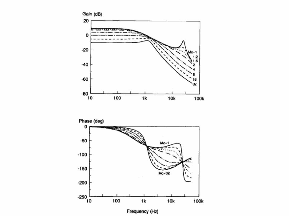
Control-to-output
'
1( ) ( )
1 0.5
op h
sic c
v RF s F s
RTRv m DL
p
1F ( )
1
c
p
sCRs
s
'1( 0.5)s
p c
Tm D
CR LC
h 2
2
1F ( )
1n p n
ss sQ
p '
1Q
( 0.5)cm D

Audio Susceptibility'
'
s
(1 )2
( ) ( )0.5
RT
co
p h
g c
DD m D
vF s F s
Lv m D
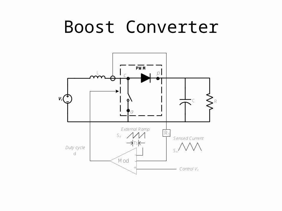
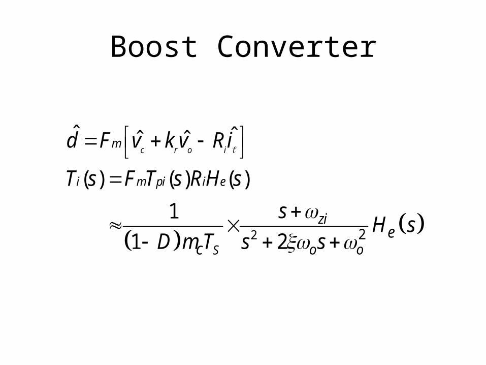
Boost Converter
RC
L
Vi
PWM
Ri
Duty cycle
Mod--+
c
a
p
Sensed CurrentTs
External Ramp
Se
Sn
Control Vc
d

Boost Converter
2s i
f
T Rk
L
2(1 )
2s i
r
D T Rk
L
L
rc
CRiv
dD
Vap ˆ
dI cˆ
v
ovi
vDˆ
p
a
Zc
dFm
kf
+
+
+
kr
PWM
Cr
i
-
cv
He(s) Ri

Boost Converter
1
1
ˆ ˆˆ
ˆˆ ˆ(1 )
1
(1 )
o
c
oc
Dv vi
Z
i D i I d
Z r sL
VI
D R
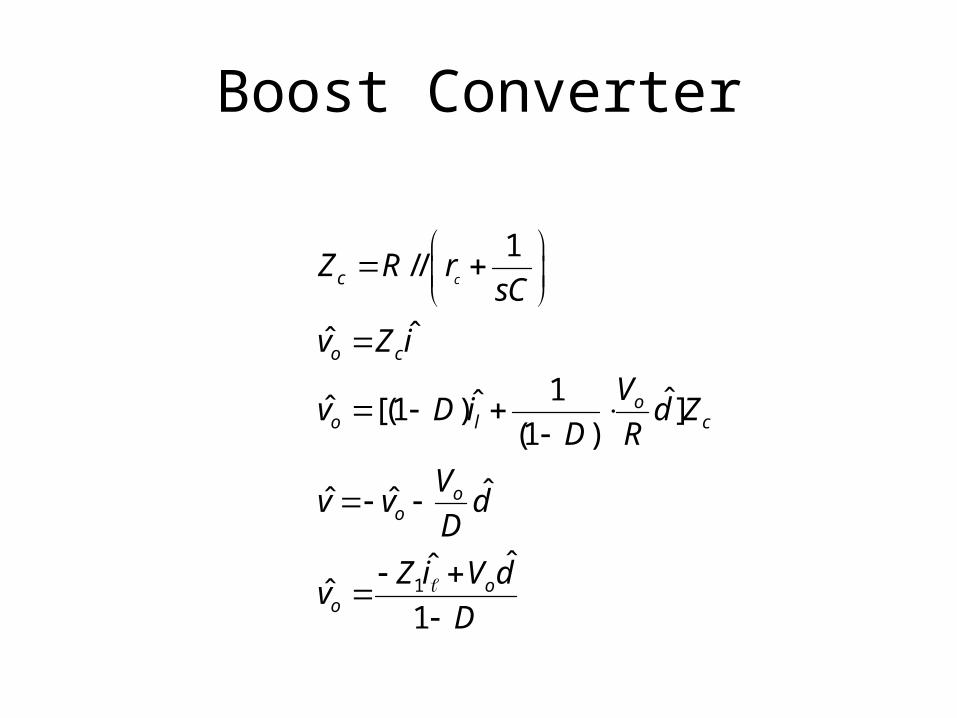
Boost Converter
1
1//
ˆˆ
1 ˆˆˆ [(1 ) ](1 )
ˆˆ ˆ
ˆˆˆ
1
cc
o c
oo l c
oo
oo
Z R rsC
v Z i
Vv D i d Z
D R
Vv v d
D
Z i V dv
D
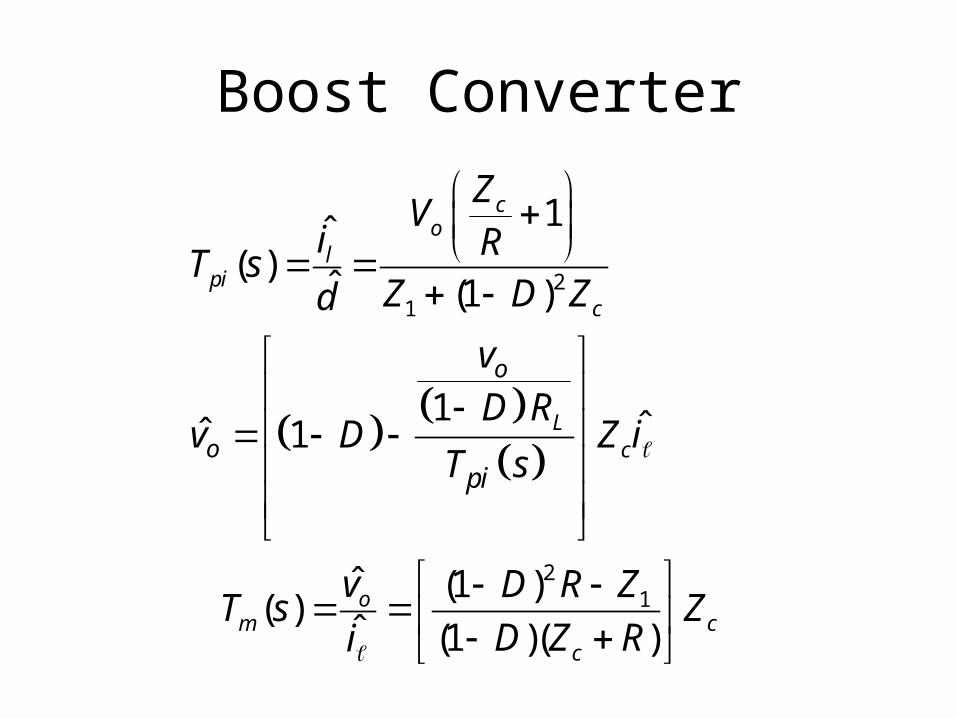
Boost Converter
21
21
1ˆ( )
ˆ (1 )
1 ˆˆ 1
ˆ (1 ) ( )
ˆ (1 )( )
co
lpi
c
Lc
om c
c
o
opi
ZV
i RT s
Z D Zd
v
D Rv D Z i
T s
v D R ZT s Z
D Z Ri
Boost Converter
2 2
ˆ ˆˆ ˆ
( ) ( ) ( )
1
1 2
c r o im
i m pi i e
S
zi
o oe
c
d F v k v Ri
T s F T s R H s
sH s
D m T s s

2
2
1
( ) (1 )
2 ( ) (1 )
1
2(1 )
ec
n
C L C
C
Sm
S
C r R r R r D L
LC R r r D R
L
D R C
2
0
2
1 1
( )
1 2
( / 2 )
( ) 1
2
C
ziC
ez n n
ns
z
D R r D
LC R r LC
C R r CR
s sH s
Q
T
Q


dcv
+
+
+
- ov
Ti(s)
Fm Tpi(s) Tm(s)
He(s) Ri
kr
i