Current commutated chopper
25
Current Commutated Chopper Submitted to: Submitted by: Mrs Shimi S.L Jyoti Singh Assistant Professor (EE Dept) ME ( Regular-2014) NITTTR, Chandigarh I & C 2 nd Sem Roll No: 142511
-
Upload
nitttr-chandigarh -
Category
Technology
-
view
85 -
download
1
Transcript of Current commutated chopper

Current Commutated Chopper
Submitted to: Submitted by:
Mrs Shimi S.L Jyoti Singh
Assistant Professor (EE Dept) ME ( Regular-2014)
NITTTR, Chandigarh I & C 2nd Sem
Roll No: 142511

What is meant by current commutation?
• Chopper is used to change the dc level of voltage,it is dc/dc converter.
• In current commutated chopper , as the namesuggests, chopper is commutated by currentpulse.
• In this process, a current pulse is made to flow inthe reverse direction through the conductingthyristor and when the net thyristor currentbecomes zero, it is turned off.

• Some assumption are:
Load current is constant.
SCR and Diodes are ideal switches.
RC is so large such that it can be treated asopen circuit during the commutationinterval.
• The energy for commutation comes fromenergy stored in capacitor.
• Capacitor is charges to Edc , so that energy forcommutation is available.

At to Thyristor T1 is turned on by gate pulse g1.

• Main thyristor T1 is fired at t=0 so that loadcurrent and output voltage is IO and VS
respectively from t0 to t1 .
• With the turning on of T1 commutationcircuitry remain inactive.
• Commutation process begins with turning onof T2.
• The commutation process is divided in variousmodes as follows.
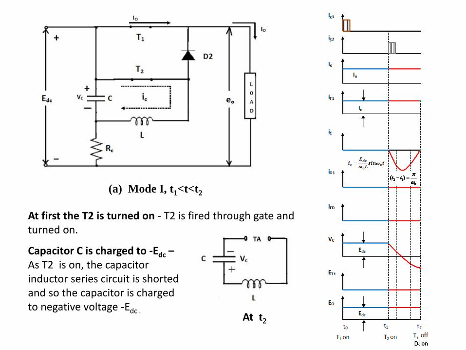
(a) Mode I, t1<t<t2
At t2
At first the T2 is turned on - T2 is fired through gate andturned on.
Capacitor C is charged to -Edc –As T2 is on, the capacitorinductor series circuit is shorted and so the capacitor is charged to negative voltage -Edc .
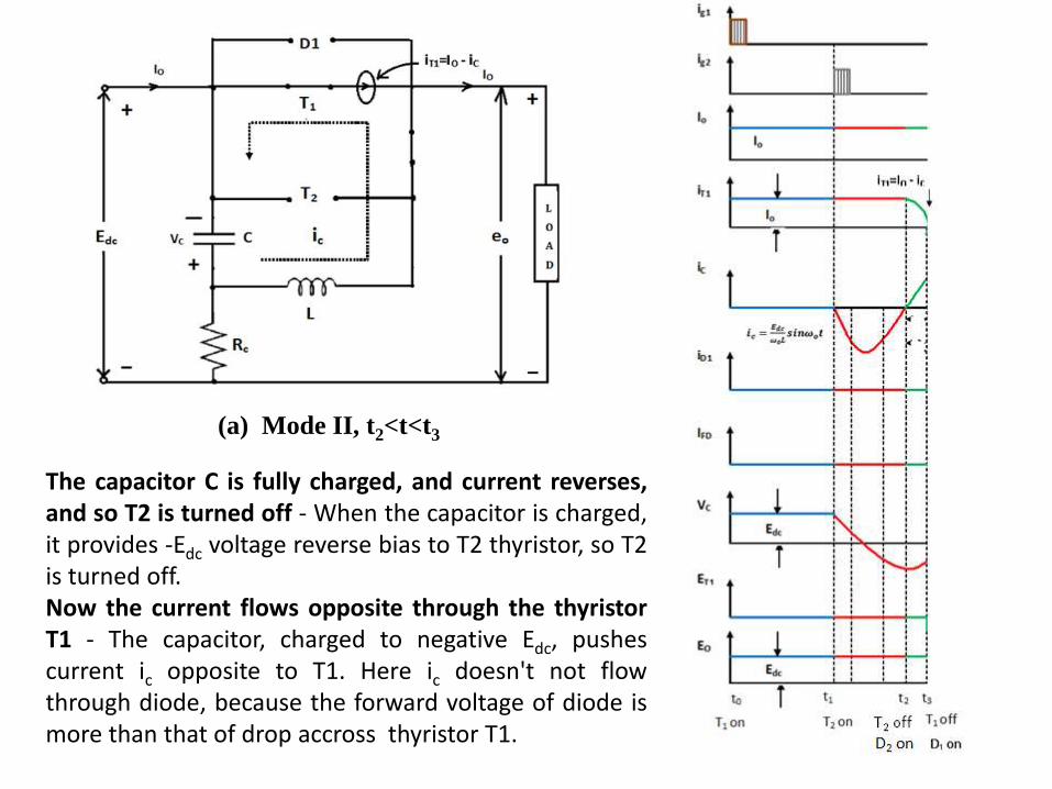
(a) Mode II, t2<t<t3
The capacitor C is fully charged, and current reverses,and so T2 is turned off - When the capacitor is charged,it provides -Edc voltage reverse bias to T2 thyristor, so T2is turned off.Now the current flows opposite through the thyristorT1 - The capacitor, charged to negative Edc, pushescurrent ic opposite to T1. Here ic doesn't not flowthrough diode, because the forward voltage of diode ismore than that of drop accross thyristor T1.

(a) Mode III, t3<t<t4
T1 is turned off- Now the ic turns off T1. So the impedance offered by T1 is more than diode, and the current ic flows through diode.

(a) Mode IV, t4<t<t5
The D1 is reversed biased - The current icslowly decrease, and when ic=Io, the diodeD1 is no longer forward biased. So thediode is turned off.

(a) Mode IV, t5<t<t6
C is charged to +Edc : C isovercharged, free wheeling diode isforward biased and Eo is reduced tozero. Io=ic+ifd.

The commutation period iscomplete. The T1 is turned onby gate pulse. And again T2 isturned on, capacitor chargesto negative potential and cyclerepeats.

What are the advantages of current commutated chopper?
• The capacitor always remains charged with the
correct polarity.
• Commutation is reliable as load current is less
than the peak commutation current ICP.
• The auxiliary thyristor T2 is naturally commutated
as its current passes through zero value.

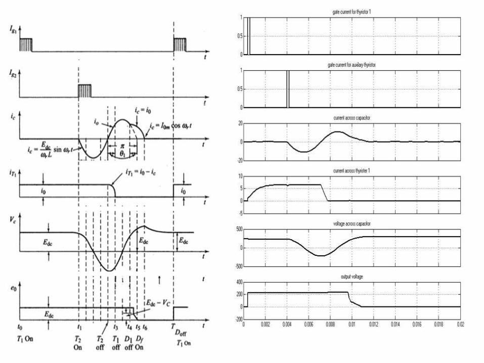
MATLAB Simulink Model

Design Consideration : Finding values of L & C
(i) Peak Commutating Current ICP > Load Current IO. The oscillating current in commutation circuit is given by
……….. (1)
(ii) Circuit turn off time must be greater than turn off time of main Thyristor.
tItL
CVi oCPosc sinsin osCP I
L
CVI
os xIL
CV
o
CP
I
Ix
xI
I
II
t
ttt
o
CP
oCP
co
c
1sinsin
sin
2
11
1
1
1
34

Circuit turn off time for main Thyristor
………………. (2a)
………………..(2b)
The above relation reveals that as load current Io increases , turn off time of main thyristor decreases. So,
……………....(3)
Substitution of above value in eq (1)
…………………(4)
)sin2(1
)2(1
1
0
1
CP
oc
o
c
I
It
t
L
tC
LCt
x
c
xc
)](sin2[
)](sin2[
11
11
)](sin2[
)](sin2[
11
11
xo
cs
o
x
cs
xI
tVL
xIt
L
V

• From eq. (3)
• Subsituting this value in eq (1)
……………….(5)
CtL
x
c
)](sin2[11
11
)](sin2[
)](sin2[
11
11
xs
co
x
c
so
V
txIC
Ct
VxI

Total Communication Interval:(t6-t1)= (t2-t1) + (t4-t2) + (t5-t4) + (t6-t5)
• (t2-t1): time period of half cycle of oscillating current
• (t4-t2) : Sine current waveform of ic is examined
• (t5-t4) : Increase in voltage across C during (t5-t4) = Vs - Vs sin(90-θ1)
LCo
LCo
)( 11
o
s
o
s
sso
ICV
ICVtt
tt
VVCI
1145
45
1
cos1)90sin(1)(
)(
)90sin(
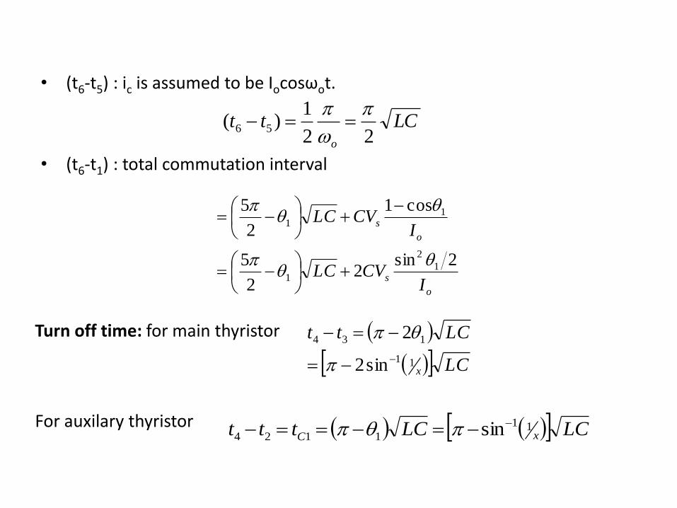
• (t6-t5) : ic is assumed to be Iocosωot.
• (t6-t1) : total commutation interval
LCtto 22
1)( 56
o
s
o
s
ICVLC
ICVLC
2sin2
2
5
cos1
2
5
1
2
1
11
Turn off time: for main thyristor
For auxilary thyristor
LC
LCtt
x11
134
sin2
2
LCLCttt xC11
1124 sin

Peak Capacitor Voltage
• Maximum capacitor VCP is reached at t6 which is equal to voltage at t5 +
voltage rise due to the energy transfer from L to C during t6 - t5
• At t5 energy in L is ½ L Io2 and at t6 this energy is transferred to C. Thus
C
LIVV
C
LIV
LICV
osCP
oc
oc
22
2
1
2
1

Numerical problems
a) For a current commutated chopper, peak commutating current is twice the maximum possible load current. The source voltage is 230 V dc and main SCR turn off time is 30 µsec. For a maximum load current of 200A, calculate
(i) The values of the commutating inductor and capacitor.
(ii) Maximum capacitor voltage and
(iii) The peak commutating current.
SOLUTION:
Given x=2, tq = 30 µsec
tC = tq + Δt
taking Δt= 30 µsec, tC =(30+30) µsec=60 µsec
(i) Value of inductor)](sin2[ 11
xo
cs
xI
tVL

Value of capacitor
(ii) Peak capacitor voltage
(iii) Peak commutating current
HL
473.16)](sin2[2002
1060230
211
6
FC
V
txIC
xs
co
822.49)](sin2[230
sec302002
)](sin2[
211
11
voltsV
C
LIVV
CP
osCP
345822.49
473.16200230
AxII oCP 4002002

b. A current commutated chopper is fed from a dc source of a 230V. Its commutating components are L=20µH and C=50µF. Is a load current of 200A is assumed constant during commutating process, then compute the following;
(i) Turn off time of main thyristor
(ii) Total commutation interval
(iii) Turn off time of auxiliary thyristor
SOLUTION:
(i) Peak commutating current
Turn off time of main thyristor8183.1
200
33.363
33.36350
20230
CP
O
CP
sCP
I
Ix
AI
L
CVI
sec52.62105020)](sin2[
)](sin2[
128183.1
11
11
c
xc
t
LCt

(ii) Total commutation interval
(iii) Turn off time of auxiliary
O
CP
O
I
I365.33
33.363
200sinsin 11
1
sec427.239
10477.91095.229
200
363.33cos12301050101000
180
365.33
2
5
66
66
O
sec931.80101000180
365.33
sin
6
11
1
LCLC x

THANKS….!