CUAir: Cornell University Unmanned Aerial Vehicle Team...CUAir: Cornell University Unmanned Aerial...
20
CUAir: Cornell University Unmanned Aerial Vehicle Team John Townsend Burgess, III, Team Leader Ameya Agaskar, CS Group Leader Timothy Szwarc, Mechanical Group Leader Joseph Vulih, Electrical Group Leader Fletcher Rothkopf, Graduate Consultant Jennifer Dooly, Business Group Leader Michael Questo Brian Chu Chris Dunphy Nate Goodell Steven Gordon Ankur Kumar Devrin Talen Neetika Bachlaus Jessica Granoff Doug Kutz Justin Leow Karan Rustagi Manuel Vargas 2006 1
Transcript of CUAir: Cornell University Unmanned Aerial Vehicle Team...CUAir: Cornell University Unmanned Aerial...

CUAir: Cornell University Unmanned Aerial VehicleTeam
John Townsend Burgess, III, Team LeaderAmeya Agaskar, CS Group Leader
Timothy Szwarc, Mechanical Group LeaderJoseph Vulih, Electrical Group Leader
Fletcher Rothkopf, Graduate ConsultantJennifer Dooly, Business Group Leader Michael Questo Brian Chu
Chris Dunphy Nate Goodell Steven Gordon Ankur KumarDevrin Talen Neetika Bachlaus Jessica Granoff Doug Kutz
Justin Leow Karan Rustagi Manuel Vargas
2006
1

Abstract
In the area of aviation, it has become the next major step to move toward the useof automated control systems. It was with this goal in mind that a group of dedicatedundergraduate students at Cornell University built an autonomous model aircraft forthe 4th Annual AUVSI Student UAV Competition. The aircraft is outfitted with onboard flight and sensor systems for autonomous way point navigation and a gimbaledblack and white camera for reconnaissance purposes. The aircraft communicates withan all-in-one ground station computer via long range 900 MHz radio telemetry as wellas over UHF channel 58 for a video feed. The ground station includes real time visionprocessing software to build a complete aerial map of the terrain and a telemetryserver which allows any networked client to have real time access to any of the planessensor data. The aircraft itself is built from mainly off the shelf components withcustom modifications. The overall system is designed to be easy to build from lowcost components and easy to use, thus making it an ideal candidate for civilian lawenforcement and public works use. Examples of civilian applications include searchand rescue or monitoring national parks. It is the goal of this paper to explain thedevelopment and systems of the platform built by the team, as well as justify designdecisions.
CUAir: Cornell University Unmanned Aerial Vehicle Team 2

Contents
1 Introduction 4
2 Overview 42.1 Mission Goals . . . . . . . . . . . . . . . . . . . . . . . . . . . . . . . . . . . 42.2 Design Process . . . . . . . . . . . . . . . . . . . . . . . . . . . . . . . . . . 52.3 System Overview . . . . . . . . . . . . . . . . . . . . . . . . . . . . . . . . . 5
3 Mechanical Systems 63.1 Airframe . . . . . . . . . . . . . . . . . . . . . . . . . . . . . . . . . . . . . . 63.2 Canopy . . . . . . . . . . . . . . . . . . . . . . . . . . . . . . . . . . . . . . 63.3 Motor . . . . . . . . . . . . . . . . . . . . . . . . . . . . . . . . . . . . . . . 73.4 Launcher . . . . . . . . . . . . . . . . . . . . . . . . . . . . . . . . . . . . . . 7
4 Electrical Systems 84.1 Kestrel Autopilot . . . . . . . . . . . . . . . . . . . . . . . . . . . . . . . . . 84.2 Ground Station . . . . . . . . . . . . . . . . . . . . . . . . . . . . . . . . . . 104.3 Camera . . . . . . . . . . . . . . . . . . . . . . . . . . . . . . . . . . . . . . 114.4 Video Transmitter . . . . . . . . . . . . . . . . . . . . . . . . . . . . . . . . 114.5 Power System . . . . . . . . . . . . . . . . . . . . . . . . . . . . . . . . . . . 124.6 Aircraft Tracker . . . . . . . . . . . . . . . . . . . . . . . . . . . . . . . . . . 12
5 Software Systems 135.1 Virtual Cockpit Control Software . . . . . . . . . . . . . . . . . . . . . . . . 135.2 Vision Processing . . . . . . . . . . . . . . . . . . . . . . . . . . . . . . . . . 14
5.2.1 Overview . . . . . . . . . . . . . . . . . . . . . . . . . . . . . . . . . 145.2.2 Program . . . . . . . . . . . . . . . . . . . . . . . . . . . . . . . . . . 15
5.3 Teleserver . . . . . . . . . . . . . . . . . . . . . . . . . . . . . . . . . . . . . 165.3.1 Overview . . . . . . . . . . . . . . . . . . . . . . . . . . . . . . . . . 165.3.2 Design and Implementation . . . . . . . . . . . . . . . . . . . . . . . 165.3.3 Client Interaction with the Telemetry Server . . . . . . . . . . . . . . 18
6 Conclusion 18
7 Appendix I: Flight Checklist 18
8 Appendix II: Safety Report 198.1 General Safety Rules . . . . . . . . . . . . . . . . . . . . . . . . . . . . . . . 198.2 Fail-safe Procedures . . . . . . . . . . . . . . . . . . . . . . . . . . . . . . . . 20
9 Acknowledgment 20
CUAir: Cornell University Unmanned Aerial Vehicle Team 3
1 Introduction
This year the Cornell UAV Team continued development on the robust foam flight platformthat it developed last year, making minor modifications to the airframe and introducing a newautopilot designed by Procerus Technologies. While several of the on board systems wouldappear to be unchanged from last year, there have been slight modifications made to makethem more reliable and to make the aircraft operate more effectively. These advancementscombined with an all encompassing ground station gives this year’s entry more user friendlycontrol and brings this design closer to a commercially viable product.
2 Overview
2.1 Mission Goals
CUAir designed its platform with the goal of winning the 2006 AUVSI Student UAV com-petition. This meant the following minimum guidelines had to be met:
• Perform autonomous flight through a series of waypoints
• Return images and GPS data of targets in the area surveyed
• Complete whole mission within 40 minutes
Furthermore, additional credit would be given for the following abilities:
• Autonomous Takeoff
• Autonomous Landing
• Dynamic re-tasking while in flight
• Minimum required time
Finally, the mission would be considered a failure if any of the following were to occur:
• Time goes past 40 minutes
• The vehicle descends below 50 ft. during flight
• The vehicle leaves the mission boundary areas
• Any flight systems fail or cause a danger to the team or spectators
With these goals in mind, CUAir designed its system to not only fulfill these goals, butalso excel in the areas of ease of use, reliability, modularity, cost, time and effort to construct,and most importantly safety.
CUAir: Cornell University Unmanned Aerial Vehicle Team 4

2.2 Design Process
The CUAir design process involved identifying the goals listed above, evaluating our currentsystems, proposing and analyzing alternative solutions to its shortcomings, implementingand testing those solutions, and then repeating the process as necessary. CUAir’s currentdesign reflects the lessons learned in the first year of using the platform. A foam delta wingwas a feasible system, and most of its weaknesses were in the autopilot and electrical systems.The team therefore restructured its design around Procerus Technologies’ Kestrel autopilotsystem, which integrated autonomous and manual control, communication, and navigationfeatures.
CUAir’s testing process involves adding one component at a time to a working system toensure that failues can be easily traced and eliminated. This saves much time and effort inthe system debugging process. Recent adjustments to the plane’s structure and protectivecanopy in order to protect flight systems allow for more reusability in the event of a crash,which results in less productive time lost.
2.3 System Overview
Figure 1 shows a schematic representation of our system layout. Our aircraft is an 83 inwingspan custom-made foam delta-wing airframe. It is powered by a 24V AXI brushlessmotor and carries a payload of up to 14 lbs, including the autopilot systems, a gimbaledcamera, a Ham band video transmitter, and batteries. There are two channels of communi-cation: the data and control line, a 900MHz serial modem connection; and the video feedtransmitted on UHF channel 58. The ground station computer, which receives data from theplane and controls its operations, also runs a telnet server, enabling networked computersto access the plane’s data.
Figure 1: System Overview
CUAir: Cornell University Unmanned Aerial Vehicle Team 5
3 Mechanical Systems
3.1 Airframe
This year CUAir continued its development of a delta wing UAV. The plane is still made upof two types of foam: a sturdy foam for the body and a softer foam for the leading edge.Thenose of the aircraft now has a composite fiberclass cover. Reenforcing this section of theleading edge shifts the center of gravity farther forward and protects the foam from sharpobjects on landing. The original goal for this year to was make the entire frame out of ashell of fiberglass, allowing all components to sit inside the plane. Unfortunately in orderto make the fiberglass thick enough so that it did not warp in flight the shell would be tooheavy.
By using a glider design the aircraft is able to acheive a stall speed of approximately20ms while fully laden. The fully loaded airframe weighs less than it did last year, due toa selection of lighter electrical components and cutting down on the number of systems onboard.
The foam construction also makes our aircraft extremely resilient. The wing is able toland on nearly any surface, making runways unnecessary. Looking ahead to future militaryapplications, this feature is essential for a craft of this size and range. The only two controlsurfaces are the elevons on the trailing edges of the wings. Carbon shafts and strips along thespan ensure that no warping occurs, and the design is incredibly stable and free of buffeting athigh speed. The foam also helps to dampen any vibrations, resulting in precision navigationalreadings not found on other planes. With so many advantages, we see our airframe as thestart of a revolution in UAVs.
3.2 Canopy
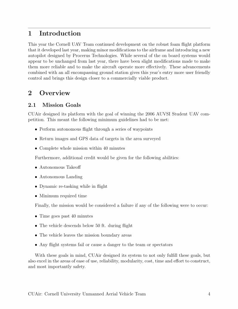
Figure 2: The Airframe with Canopy
Since cutting many holes in thefoam wing would damage itsstructural integrity, the electricomponents are bolted securely tothe top of the plane (the single ex-ception being the gimballed cam-era.) A thin layer of plywood isepoxied to center section of theplane to give the components asturdy surface to be secured to.A fiberglass canopy, formed overa foam mold, is used to protectthe electronics during flight.
The canopy was designed tomaintain the center of gravity andgive the plane the most stability. A foam mold was built by gluing cross sections together.The mold was then covered with packaging tape, which would allow the fiberglass to peeloff easily. Then four layers of lightweight fiberglass were applied with epoxy.
CUAir: Cornell University Unmanned Aerial Vehicle Team 6

This year’s canopy is more flexible and narrower than the canopy used last year. Byreducing the size and number of electrical components the canopy was able to be reducedin size. This reduction in size reduces drag from the canopy and improves airflow over themotor which is at the rear of the canopy. The flexibility of the canopy is important: in acrash, instead of the canopy cracking and allowing components to be damaged, it flexes andabsorbs the impact.
3.3 Motor
Figure 3: A close-up of themotor
The CUAir UAV is still driven by an AXI 4130/16 model elec-tric motor with a 16x8 in prop, powered by two 3 cell lithiumpolymer batteries in series. This motor was chosen last yearbecause it produces a lot of thrust while the plane is climbingor moving at high speed, yet is still efficient at low speeds.
The use of an electric motor over a gas motor gives theplane more flexibility. An electric motor is lighter, and thebatteries can be placed anywhere in the plane to move thecenter of gravity. While charging batteries between flightstakes longer than simply refueling an engine, with a chargetime of one hour and the a maximum flight duration of two,simply having two sets of batteries can keep the plane continuously flying with short landingsevery hour and a half.
3.4 Launcher
Based on positive past experiences, the team decided to keep the assisted launch systemfirst demonstrated at the 2005 competition. This system uses an electric winch and launchramp setup. The launch ramp is primarily made of one-inch diameter PVC piping and PVCcouplings, with the top surface being made of slightly larger diameter pipes to provide asmooth take-off surface between the pipes and couplings. The two launch rails consist ofsmooth PVC pipe about 6 ft long. The ramp is angled upward, so during takeoff the planehas a positive angle of attack.
As the plane sits on the ramp awaiting take-off, the electric winch is set up alongsidethe launcher. This is a superskeg supplied starter motor, powered by an external 12V carbattery. When powered, this winch reels in a spool of nylon winch line which has been feedthrough a turnaround pulley and then to a ring and hook mechanism on the plane. Thismechanism consists of a “launch-hook” which is attached to the plane and a ring attachedto the winch line. The hook is swept back and is secured to the underside of the aircraftthree inches forward of the CG. The location of the launch hook was found through manyiterations of trial and error. If the hook is too far forward, it will pull the nose of the planedown during takeoff negating any positive lift created, whereas if it is too far aft, it will bepulling from behind the center of gravity causing an unstable launch and even a stall of theplane.
Once the launch hook is properly attached, the ring is placed in the hook. When thewinch is powered on, it accelerates the plane up to a rollout speed of 15ms over a period
CUAir: Cornell University Unmanned Aerial Vehicle Team 7

of 2-4 seconds. The ring falls off the hook either when the plane is over the pulley or whenthe winch is switched off. By using an externally powered launch mechanism we are able toextend flight time because no on board power is used to launch the plane.
Figure 4: Fully Assembled Launcher
Another advantage that this launch mecha-nism has over a conventional runway is that theplane does not require a smooth surface to takeoff from. The winch and pulley can be stakedor weighted down on any sort of ground. Theplane is also accelerated up to speed faster thana conventional fixed wing aircraft and can thusgain altitude quicker. These advantages give theplane terrain flexibility over conventional takeoffs, making this design more versatile. It is pos-sible to launch the aircraft from rocky groundusing this system, and land it elsewhere for re-covery. The launch ramp is collapsible into 3sections. The sections of the PVC pipe thatmake up each section are strung together liketent poles. This makes set up extremely stream-lined and can be done by a single individual.
4 Electrical Systems
4.1 Kestrel Autopilot
Because of the requirement for UAVs to be fully autonomous without any assistance fromthe ground, CUAir sought to find the most flexible and operable autopilot system availableon the commercial market for their UAV. Last year, CUAir utilized the MicroPilot autopilotplatform to control the UAV aircraft. However, in using this platform the team ran intonumerous difficulties in obtaining reliable performance from the autopilot which greatlyaffected their performance during the summer AUVSI UAV competition.
The Kestrel Autopilot System developed by Procerus Technologies presented itself asan effective and robust platform upon which to build the team’s UAV around. One ofthe most striking aspects was its significant size advantage in that it only weighed 16.65 gwith dimensions at 2x1.37x.47 in. These dimensions include the autopilot’s modem used forcommunication to the ground station, a large improvement over the bulky external modemrequired by the MicroPilot in the previous year. Such space improvements are significantbecause they in turn allow greater flexibility in the payload distribution on an aircraft whereevery pound makes a difference.
By incorporating a complete gamut of sensors including a magnetometer, 3 temperature,and 2 air pressure sensors in addition to the usual measurement of the 6 degrees of freedomof an aircraft, the Kestrel provides the user with a great deal of accuracy in reflecting thestate of the aircraft. The magnetometer is utilized to aid in providing readings for aircraftheading during low-speeds or when the aircraft is stationary and is unable to obtain heading
CUAir: Cornell University Unmanned Aerial Vehicle Team 8

information from the external GPS unit. The 3 temperature sensors on the aircraft are usedin conjunction with a compensation algorithm in order to reduce the need to re-calibrategyros or pressure sensors because of the effect of temperature variation on the readings.The air pressure sensors reflect both barometric pressure of the aircraft at its flying altitudeas well as airspeed. Combined with GPS information, the Kestrel is also able to use thisinformation to provide an estimate on wind speed and heading, accurate to 5% and 2%respectively. With these sensors the Kestrel provides information at a level unmatched bythe MicroPilot.
Figure 5: The Kestrel 2.2 Autopilot
Another advantage the Kestrel provides isbuilt-in support for an onboard camera gimbalsystem. This is crucial because it allows full usercontrol over the video camera that is mountedon the underside of the aircraft. Through theground station the user is able to manually ma-nipulate the camera via joystick. The Kestrelalso has the ability to stabilize a gimbaled cam-era. By adjusting the servo bias and the scalarsany sort of payload that incorporates two servosfor stabilization can be calibrated.
Flexibility of operation is another definingaspect for the Kestrel. Its power consumptionis regulated only to its requirements, extending
battery life. In addition, the Kestrel provides the user with real-time battery life informationalong with a variety of other information and tools in Procerus’s proprietary Virtual Cockpitground control software. In addition to its 4 servo ports, the Kestrel also is able to supportanother 2 servos for aircraft operation through an external servo board. This external servoboard is used by CUAir to control the camera gimbal.
The Kestrel communicates to the ground via a pair of 900MHz modems, one connectedvia a header to the Kestrel, and the other housed in the Commbox on the ground. TheKestrel is designed to work with the Aerocomm AC4490-1000 modem. Because the autopilotis designed to work with this modem there are minimal compatibility issues. The modemsbroadcast at 1000mW and has been tested up to a range of 10 km in open air with line ofsight with minimal packet loss. With this range the aircraft is far out of sight before anyloss of communication can be expected.
There are numerous fail-safe settings that will engage the aircraft in predefined actionsshould the Kestrel face undesirable situations such as loss of communication. The situationsthat have defined fail-safe responses are:
• loss of GPS for a specified period of time
• loss of communication to the ground for a specified period of time
• low battery voltage
For each of these scenarios the user can set up two values for which the Kestrel will performdifferent actions. For example, the user can set the fail-safe so if the battery level drops
CUAir: Cornell University Unmanned Aerial Vehicle Team 9
below 10V the plane starts on a flight path toward the home GPS coordinate, which ispredefined at the beginning of each flight. Once the battery level drops below an even loweruser specified point, the plane will bring itself down immediately to prevent shutting downwhile throttle is still on. Any problems that are encountered can be fully examined throughVirtual Cockpit’s integrated data logging.
Through Virtual Cockpit, the aircraft can also be told to engage in several predefined“modes”, which include holding speed or altitude, flying home, or loitering around a way-point. The aircraft can also be told to engage in convoy following mode if a GPS unit ishooked up with the commbox to provide a constantly updated (if moving) “home” positionfor the aircraft to follow. If so desired, Virtual Cockpit also has the power to manage multipleUAVs simultaneously through one ground station.
With amount of control and functionality offered, CUAir is confident that the Kestreland its supporting software Virtual Cockpit will fully serve their needs in developing acompetition-ready aircraft.
4.2 Ground Station
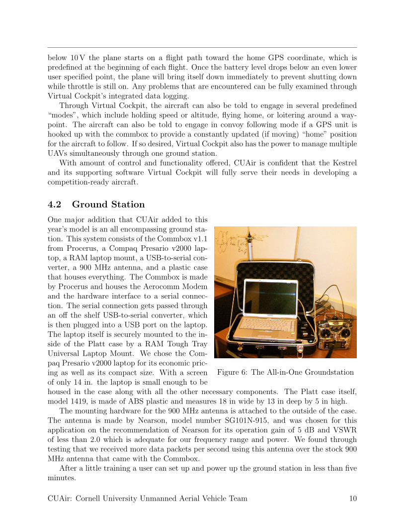
Figure 6: The All-in-One Groundstation
One major addition that CUAir added to thisyear’s model is an all encompassing ground sta-tion. This system consists of the Commbox v1.1from Procerus, a Compaq Presario v2000 lap-top, a RAM laptop mount, a USB-to-serial con-verter, a 900 MHz antenna, and a plastic casethat houses everything. The Commbox is madeby Procerus and houses the Aerocomm Modemand the hardware interface to a serial connec-tion. The serial connection gets passed throughan off the shelf USB-to-serial converter, whichis then plugged into a USB port on the laptop.The laptop itself is securely mounted to the in-side of the Platt case by a RAM Tough TrayUniversal Laptop Mount. We chose the Com-paq Presario v2000 laptop for its economic pric-ing as well as its compact size. With a screenof only 14 in. the laptop is small enough to behoused in the case along with all the other necessary components. The Platt case itself,model 1419, is made of ABS plastic and measures 18 in wide by 13 in deep by 5 in high.
The mounting hardware for the 900 MHz antenna is attached to the outside of the case.The antenna is made by Nearson, model number SG101N-915, and was chosen for thisapplication on the recommendation of Nearson for its operation gain of 5 dB and VSWRof less than 2.0 which is adequate for our frequency range and power. We found throughtesting that we received more data packets per second using this antenna over the stock 900MHz antenna that came with the Commbox.
After a little training a user can set up and power up the ground station in less than fiveminutes.
CUAir: Cornell University Unmanned Aerial Vehicle Team 10

4.3 Camera
Figure 7: The EverFocusCCD Camera
To capture the image while the vehicle is in flight, a CCDboard camera was chosen rather than a CMOS camera be-cause, in general, a CCD camera give better image resolutionwith less noise than a CMOS image sensor. A black and whitecamera was chosen over a color CCD camera, because the vi-sion algorithms discussed use only the brightness information,and a color camera with the same stated resolution as a blackand white camera will filter out more light and have a lowerresolution brightness channel. A lens camera was selected overa pinhole camera, because a lens camera does not need as fastan exposure time, collects more light, and provides a more de-tailed image. This is ideal for a fast-moving plane. A camerawith a low illumination factor so useable imagery can be col-lected under adverse weather conditions. The Ever Focus EB110E4 was chosen bevcause itfit all of these criteria, and included the auto gain control attribute, which increases cameraperformance in low light conditions. The camera is also composed of an electronic shutter,which can stop a moving image to about 10µs. Under varying light conditions, this cameraslens iris with the shutter lets in the optimal amount of light for a crisp image. The 4.3mmlens covers a range of 58 horizontally and 45 vertically. The chosen camera also uses a 12Vpower supply, which can be connected to any other 12V battery that are already present onthe plane, such as the one powering the Kestrel autopilot.
4.4 Video Transmitter
The image received by the CCD camera is transmitted to a video receiver on channel 58using a TV transmitter. PC Electronics’ TXA5-RCb ATV TRANSMITTER BOARD wasused to broadcast the received from image from the camera. In order to stay away from FMand ATV repeater inputs, the transmission frequency used is 426.25MHz. There is a crystalcontrolled oscillator around 106MHz, which is 1/4 of the output frequency. The frequencyrange is 425 to 440MHz with a crystal tolerance of 0.005%. A stable power source of 12Vwill be used to power the transmitter. The power source should be stable as any ripple onthe supply voltage can show up as noise in the video. An RCA video jack is used to connectthe camera to the transmitter. This transmitter has been tested and is good for up to 5miles. The description of the transmitter antenna is detailed in another section.
The video is recieved on the ground by a WinTVToGo PCI card installed on a PC. Thecard has various input options, one of which is for an external antenna, eliminating the needfor any extra external hardware. The card also uses standard windows drivers so that thesignal can be easily used by other programs. The Shuttle PC runs the vision processingalgorithms written by the team to process the frames of video and stitch together an aerialmap.
CUAir: Cornell University Unmanned Aerial Vehicle Team 11
4.5 Power System
The aircraft is powered by several Lithium Polymer model airplane batteries purchased fromTower Hobbies. There are two 12 V batteies made by Thunder Power. Each battery is threecells and 8000mWhr. The batteries are connected in series to power the 24V AXI motor.There is one 12V three cell battery made by Kokam that is used to power all of the on boardelectrical systems. All on board systems were chosen to fit this 12V power supply so thatthere would be no need for voltage regulators which consume power. This single battery iscapable of powering all the systems for longer than the motor batteries can power the motor.This gives a window during which the motor can lose power but the aircraft is still capableof landing itself. The aircraft can stay aloft for close to 2 hrs on a single charge flying atcruise speeds.
4.6 Aircraft Tracker
In order properly document our test flight a video camera is used. However, the accuracyof this footage is seriously impeded upon by the skill of the cameraman (i.e. loosing sightof the plane or an unsteady shot of the plane). Hence the implementation of a groundtracking station fundamentally eliminates the human error and improves the quality of ourdocumentation.
The ground tracking station consists of three components: The Pan-Tilt Module, TheGeo-Pointing Module, and the host computer. The Pan-Tilt Module (PTU) is simply twoorthogonally connected servos mounted atop of a tripod. This set up allows the “load” (i.e.the camera) to have two degrees of freedom. The PTUs pan range is approximately +/-159 degrees (318 degree range) and its tilt range is 31 degrees up and 47 degrees down (78degree). Its angular resolution is 0.771 arc minutes (0.012857 degrees). This makes for acone shaped “blind spot” in the field of view, with its pinnacle located at the camera andits base radiating above and below it. Since the object of interest will be flying overheadthe lower limitation becomes inconsequential. The upper limitation on the other hand isof slight concern, but because the plane is moving at a high speed even if it were to flydirectly overhead, the picture of the aircraft would only be lost for a matter of seconds. TheGeo-Pointing Module (GPM) is implemented on a Netburner Mod5282 microcontroller, anduploaded via The Netburner Development C++ software. The program is stored in flashso that it will not be lost each time the system looses power. The GPM allows the PTUto point its “load” using latitude/longitude coordinates (GPS) instead of pan-tilt angles.The GPM is communicated to via TCP/IP protocols allowing it to be controlled via a hostcomputer or over a network. For our application we use a single host computer, connectedvia a Cat5 cross-over cable. The system can be controlled and calibrated manually via itsbuilt in web page interface or by using HTTP commands in DPoIP command format. Thesecommands are in the following form:
http://<ipaddr>/<verb>?cmd==<command><params> or
http://<ipaddr>/<verb>?<command>=<params>
<ipaddr> is the IP Address of the GPM
<verb> ? { "non’’ , "raw’’ } The "raw’’ form returns the result from the command.
The "non’’ command executes the command but returns no data.
?cmd==<command><params> or ?<command>=<params>
<command> is a Geo-Pointing or Pan-Tilt command
CUAir: Cornell University Unmanned Aerial Vehicle Team 12
A list of these commands can be found in the GPM’s user manual
<params> are the appropriate parameters for the given command
In order to authenticate commands issued via DPoIP a HTTP Basic AuthenticationScheme is used. When issuing DPoIP commands to the Geo-Pointing Module from a browser,the user will be prompted for a username and password. Only a valid username and passwordwill allow commands to be sent to the GPM. Calibration of the GPM is done using a builtin function that computes the orientation of the PTU in real-world coordinates (lon, lat,alt) using a set of user provided landmarks along with the GPS coordinate of the PTU. Todo this a landmarks location is entered in the form of a GPS coordinate and the PTU isthen aimed at that landmark. This process is iterated four or more times and the GPMupdates the PTUs orientation estimate accordingly. Landmarks should be chosen so as tocover a wide span of angles and distances, and although a minimum of four landmarks isrequired additional landmarks can improve the GPMs pointing accuracy. Once calibrated,the GPM is ready to accept streaming or manually entered commands and queries from thehost computer. The overall accuracy of the GPM is determined by the pointing resolutionwhich is defined during calibration. If during calibration several well spaced landmarksare used and the PTU is carefully aimed at them, the angular accuracy of the GPM willapproach the angular resolution of the PTU. The host computer is the final componentin this system. It receives one GPS coordinate from the Procerus autopilot every second,processes it via the telemetry server and forwards it to the GPM via TCP/IP protocols inthe above described DPoIP format in real time. Thus allowing the camera mounted atop ofthe PTU to constantly be pointed at the aircraft.
5 Software Systems
5.1 Virtual Cockpit Control Software
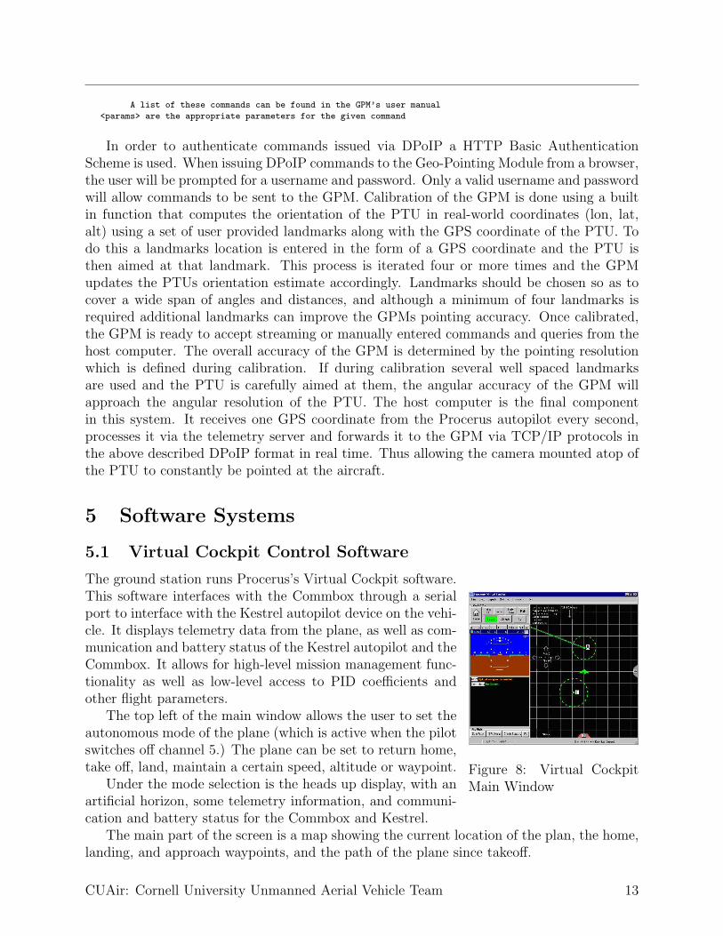
Figure 8: Virtual CockpitMain Window
The ground station runs Procerus’s Virtual Cockpit software.This software interfaces with the Commbox through a serialport to interface with the Kestrel autopilot device on the vehi-cle. It displays telemetry data from the plane, as well as com-munication and battery status of the Kestrel autopilot and theCommbox. It allows for high-level mission management func-tionality as well as low-level access to PID coefficients andother flight parameters.
The top left of the main window allows the user to set theautonomous mode of the plane (which is active when the pilotswitches off channel 5.) The plane can be set to return home,take off, land, maintain a certain speed, altitude or waypoint.
Under the mode selection is the heads up display, with anartificial horizon, some telemetry information, and communi-cation and battery status for the Commbox and Kestrel.
The main part of the screen is a map showing the current location of the plan, the home,landing, and approach waypoints, and the path of the plane since takeoff.
CUAir: Cornell University Unmanned Aerial Vehicle Team 13
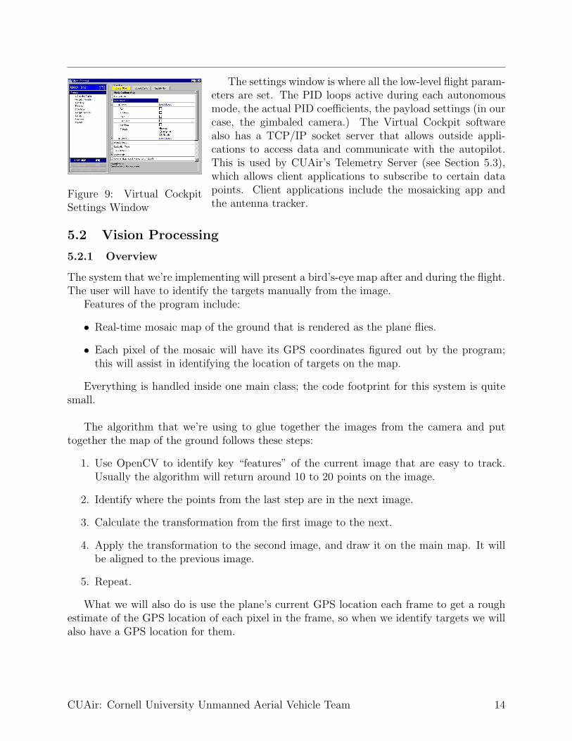
Figure 9: Virtual CockpitSettings Window
The settings window is where all the low-level flight param-eters are set. The PID loops active during each autonomousmode, the actual PID coefficients, the payload settings (in ourcase, the gimbaled camera.) The Virtual Cockpit softwarealso has a TCP/IP socket server that allows outside appli-cations to access data and communicate with the autopilot.This is used by CUAir’s Telemetry Server (see Section 5.3),which allows client applications to subscribe to certain datapoints. Client applications include the mosaicking app andthe antenna tracker.
5.2 Vision Processing
5.2.1 Overview
The system that we’re implementing will present a bird’s-eye map after and during the flight.The user will have to identify the targets manually from the image.
Features of the program include:
• Real-time mosaic map of the ground that is rendered as the plane flies.
• Each pixel of the mosaic will have its GPS coordinates figured out by the program;this will assist in identifying the location of targets on the map.
Everything is handled inside one main class; the code footprint for this system is quitesmall.
The algorithm that we’re using to glue together the images from the camera and puttogether the map of the ground follows these steps:
1. Use OpenCV to identify key “features” of the current image that are easy to track.Usually the algorithm will return around 10 to 20 points on the image.
2. Identify where the points from the last step are in the next image.
3. Calculate the transformation from the first image to the next.
4. Apply the transformation to the second image, and draw it on the main map. It willbe aligned to the previous image.
5. Repeat.
What we will also do is use the plane’s current GPS location each frame to get a roughestimate of the GPS location of each pixel in the frame, so when we identify targets we willalso have a GPS location for them.
CUAir: Cornell University Unmanned Aerial Vehicle Team 14

5.2.2 Program
This section will walk through the major sections of the code and explain what each peicedoes.
numCorners = 50;
cvGoodFeaturesToTrack( lastYImage, eigImage, tempImage, lastcorners, &numCorners,
/*quality_leve*/.3,
/*min_distance*/15.0,
/*mask*/ NULL,
/*block_size*/ 3,
/*use_harris*/ 0,
/*k*/ 0.04 );
This code accomplishes the first step given in the algorithm above. The function takesin the last image that we have, along with a few other parameters, and fills the arraylastcorners with the features to track across frames. We also do a quality check right afterthis; if we don’t have N features to track (where N is about 15 for our purposes), then we’lljust abort this frame and try again when the next frame comes.
cvCalcOpticalFlowPyrLK(lastYImage, YImage,
/*prev_pyr*/NULL,
/*curr_pyr*/NULL,
lastcorners, corners, numCorners, cvSize(10,10),
/*level*/4
,LKstatus,
/*track_error*/NULL,
cvTermCriteria(CV_TERMCRIT_ITER,10,.05),
/*flags*/0);
This function takes in both images (the one used in the previous function call and thenew image), and calculates where the feature points from the last image went in this frame,and stores the resulting points in corners.
Next the program does a little linear algebra with the resulting lastcorners and corners
arrays. A 2-d transformation of an image can be expressed as:
Ax‘ + By‘ + C = x (1)
Dx‘ + Ey‘ + F = y (2)
where (x, y) and (x‘, y‘) are the coordinates of a pixel in the previous and current frames,respectively. We want to use the features that we just picked out from both images so wecan figure out the coefficients A through F . We can use matrices to solve the system ofequations efficiently, by setting up the matrices in the following manner: x‘
y‘1
=
A B CD E F0 0 1
x
y1
The program fills the previous points and next points matrix, then uses OpenCV to solve
for the coefficients matrix. It then uses the coefficients to transform the current transformmatrix:
composeAffineTransform(curTrans,cumuTrans);
Then the program uses this transformation to draw the current frame into the right placeon the map:
cvWarpAffine(frame,mosImg,cumuTrans,0,cvScalar(255,0,0));
cvShowImage(WIN_TITLE,mosImg);
CUAir: Cornell University Unmanned Aerial Vehicle Team 15

5.3 Teleserver
Procerus provides an API to Virtual Cockpit (VC) and allows third party programs to directinteract with VC, the Commbox, and the Kestrel. However, VC cannot handle more thanone client connection at a time. In order to allow multiple applications to interact with theaircraft system, we wrote a telemetry server that mediates the communication to and fromVC and other applications.
5.3.1 Overview
The telemetry server basically functions as a data bus and repeater, and as an unauthoritativedata server. Several features of telemetry server:
• allow other third-party programs to use VC’s API transparently, functioning as a databus.
• relay VC’s broadcast packets to all connected clients, functioning as a repeater.
• cache data contained within packets that pass through, especially from packets thatare periodically sent by VC, allowing clients to asynchronously request for information.
• ability to implement a simple protocols for specialized clients that require only certaintypes of transactions.
• ability to create modules to perform pre-programmed macros or reproduce commandsthat would otherwise be tedious using the VC GUI.
5.3.2 Design and Implementation
Simply, the telemetry server is a program that uses Procerus’ API to connect to VC andlistens for connections from other clients. In more detail than it was above, we wanted it to:
• listen on the connection to VC, and, for every packet not destined for any single entity,log and broadcast the packet to all connected clients.
• listen on the connections to clients, and, for every packet not destined for the server,log and relay to VC.
• accept and report on commands to the standard input/output streams of the control-ling console. That way, operators can still interface with the server and change itsbehavior on the run.
Those operations don’t make our telemetry server any more different, in function, froma dynamically configurable relay. We also defined that our server should be able to functionas a recording and playback device to client programs. Thus, it must be able to:
• log any packet going through any part of the data flow to a file.
CUAir: Cornell University Unmanned Aerial Vehicle Team 16
• playback logfiles for client programs simulation and testing without having to be flyingout on the field.
• playback logfiles for client programs that have non-realtime algorithms (e.g. post-processing) that require a sequence of valid telemetry data. These instances couldmake use of a specialized protocol extension other than VC API.
Of course, we wanted to keep our software as platform-independent as possible withoutresorting to using byte-code interpreted languages like Java or .NET. We chose to use C++,and along with that, we incorporated the Apache Portable Runtime library to handle theplatform-dependent interface to platform-dependent operations - e.g. file IO, sockets, mem-ory allocation, concurrency control, network IO. As an extra, we were able to make use ofAPR’s memory pools as a foundation for a simple managed memory solution.
The extensibility of additional clients and processing modules is modeled after modernwindowing systems’ event handling. Like when an object wants to be notified when anevent occurs, a client object that wants to receive all non-directed VC packets adds a refer-ence to itself to an array, provided it supports the common void VCPacketArrived(struct
VCPacket *) method.The distinguished classes that were implemented are:
• VCsocket, which handles every VC communication-specific aspect of the transaction.The implementation of the specified protocol lives here.
• CLparser, which parses the command line inputs into a command/operation structthat contains all arguments.
• TSclient, which handles communications between the telemetry server and the clients.
• Logger, which is a uniform logging solution that’s integrated into all the other classes ofthe suite. Where a class has incoming data from a network socket, a Logger-compatibleinterface is also supported. This way, logged packets can be replayed at the currenttimes.
CLparser is implemented so the use of CLparser is like using a bison/yacc solution.Bison/yacc would have been used, but the project is currently being compiled using bothGNU GCC and MSVS .NET 2003, which would require extra work to keep Win32 API-compatible bison/yacc binaries, short of installing Cygwin.
TSclient and VCsocket make heavy use of APR’s network IO routines, and thus mostlyfunctions as a wrapper to any sort of networking-specific code.
Logger relies on APR’s file IO routines. However, since APR does not yet have a built-in logging functionality, Logger implements both persistent and non-persistent file loggingmodels, which takes into account the undesired lag possibly present when used in a realtimeapplication.
At the moment, caching of variable data is done by the server as local variables, andhas not been generalized to a class. When the server has been extended to be able to routeamong several VC upstream connections, a class for caching telemetry data would be madeworthwhile implementing.
CUAir: Cornell University Unmanned Aerial Vehicle Team 17

5.3.3 Client Interaction with the Telemetry Server
To date, the TSclient class in the server implements three types of protocol transactions:
1. clients wishing to communicate using only the VC API, e.g., clients in transparentoperation to VC.
2. clients wishing to communicate with the server using a specialized protocol, e.g., totake advantage of server’s variable caching.
3. clients wishing to communicate using both protocols.
TSclient assumes, by default, that all clients are communicating transparently (1). Ifthe client wishes to change the mode of communication, it must make it known in the firstpacket sent to the server. If the second mode is requested, further communication willcontinue in the defined protocol. If the hybrid mode is requested, the combined protocolrequires the first 8 bits of a packet to be an int, which is the index of the protocol: 1 for aVC packet destined for the VC uplink, 2 for a packet for the server.
Since VC supports attaching an identifying number to individual requests, which it ap-pends at the end of every response, the server keeps a table to map request numbers specifiedby a TSclient to ones it chooses to send to VC. Thus, when VC responds with the mappedrequest number, the server knows which TSclient it belongs to. This behavior is very muchlike NAT’s, where the remapping of source and destination in the IP headers of a mangledpackets must be restored by the NAT gateway before final delivery to the requesting client.
6 Conclusion
CUAir’s entry to the 2005 AUVSI Student UAV Competition is one of the most innovativeand successful UAV’s to be designed for several reasons. The unique foam delta-wing airframemakes this design economically appealing, while still being easy to use for even an untrainedpilot. When this is combined with an all-in-one, ultra-portable groundstation, it is the mostfunctional platform available.
Having the design centered around ultra-robust components, especially the Kestrel au-topilot, ensures that minimal failures will occur. We have also invested much time intocreating valuable software systems, including our mosaic-ing application, which make identi-fying ground targets as easy as possible. We believe this entry will be extremely successful,and even cause a revolution in future small-scale UAV design.
7 Appendix I: Flight Checklist
1. Prepare launcher and winch
2. Prepare and power on Groundstation
3. Power on plane electronics, except motor
CUAir: Cornell University Unmanned Aerial Vehicle Team 18

4. Power TV or Vision Groundstation and verify connections
5. Perform range test of plane to groundstation, verify GPS lock
6. Validate all control surfaces respond correctly
7. Verify pilot is able to put plane in and out of autopilot mode safely
8. Perform autopilot self-test on all sensors and reactions
9. Have one person supply power to plane while holding it on launcher for throttle test
10. Safely secure canopy to plane
11. Begin Countdown and Takeoff
Upon landing
1. Remove canopy and remove power to throttle
2. Retrieve data logs and download any other pertinent information from Kestrel
3. Perform any post processing on vision station
4. Power down autopilot and plane electronic systems
5. Break down launcher and Groundstation at end of last test flight
8 Appendix II: Safety Report
8.1 General Safety Rules
• All people at a test flight operating equipment or near the aircraft are required to wearsafety glasses at all times.
• Use of any power tools or other dangerous materials should be accompanied by properpersonal safety protection, such as goggles, gloves, aprons, closed toed shoes, etc.
• While not in use all batteries, LiPoly, NiCd, and others, are to be kept in the fire safein the lab.
• At all times while batteries are being charged they are to be clear of any combustablematerial and kept under constant observation.
• Prior to powering the throttle on the aircraft varify all areas around the plane are clearand that no one is in the plane of the propeller or behind.
• Prior to flight all bolts and components on the aircraft are to be checked to make surethey are secure and will not become detached.
• If at any time the plane becomes unstable and the pilot cannot control it manually, itis to be brought down as quickly as possible in an open area clear of people.
CUAir: Cornell University Unmanned Aerial Vehicle Team 19
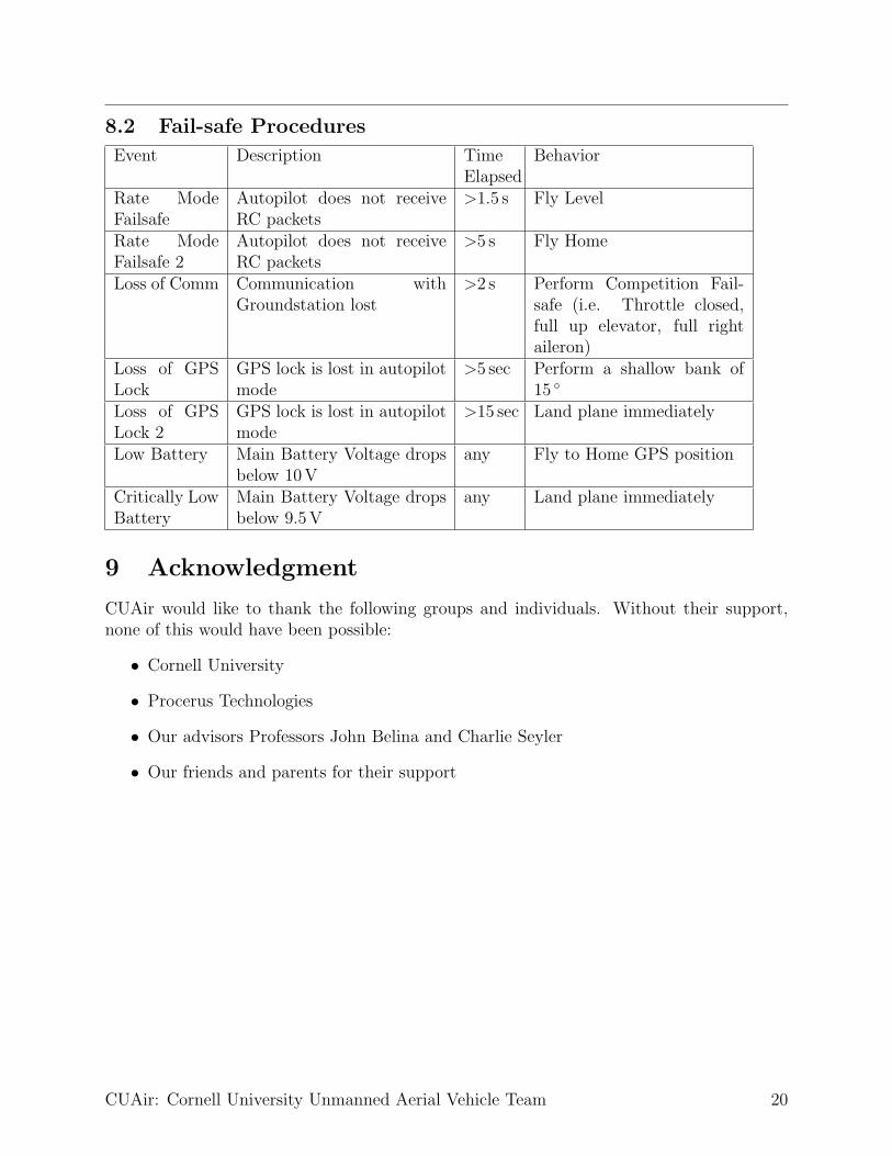
8.2 Fail-safe Procedures
Event Description TimeElapsed
Behavior
Rate ModeFailsafe
Autopilot does not receiveRC packets
>1.5 s Fly Level
Rate ModeFailsafe 2
Autopilot does not receiveRC packets
>5 s Fly Home
Loss of Comm Communication withGroundstation lost
>2 s Perform Competition Fail-safe (i.e. Throttle closed,full up elevator, full rightaileron)
Loss of GPSLock
GPS lock is lost in autopilotmode
>5 sec Perform a shallow bank of15 ◦
Loss of GPSLock 2
GPS lock is lost in autopilotmode
>15 sec Land plane immediately
Low Battery Main Battery Voltage dropsbelow 10V
any Fly to Home GPS position
Critically LowBattery
Main Battery Voltage dropsbelow 9.5V
any Land plane immediately
9 Acknowledgment
CUAir would like to thank the following groups and individuals. Without their support,none of this would have been possible:
• Cornell University
• Procerus Technologies
• Our advisors Professors John Belina and Charlie Seyler
• Our friends and parents for their support
CUAir: Cornell University Unmanned Aerial Vehicle Team 20


![FY18 RWDC State Unmanned Aerial System Challenge ... · Unmanned Aerial System Challenge: Practical Solutions to ... , Real World Design Challenge ... , unmanned aerial vehicle [UAV])](https://static.fdocuments.us/doc/165x107/5ae85cfb7f8b9a8b2b8fe5e5/fy18-rwdc-state-unmanned-aerial-system-challenge-aerial-system-challenge-practical.jpg)