CU-HD1000 Operation Manual - Hitachi Kokusai Electric America, Ltd
38
CAMERA CONTROL UNIT CU-HD1000 OPERATING INSTRUCTIONS Please read these operating instructions carefully for proper operation, and keep them for future reference.
Transcript of CU-HD1000 Operation Manual - Hitachi Kokusai Electric America, Ltd

CAMERA CONTROL UNIT
CU-HD1000
OPERATING INSTRUCTIONS
Please read these operating instructions carefully for proper operation, and keep them for future reference.
Note: The model and serial numbers of your product are important for you to keep for your convenience and protection. These numbers appear on the nameplate located on he bottom of the product. Please record these numbers in the spaces provided below, and retain this manual for future reference. Model No. Serial No.
A
SAFETY INSTRUCTIONS Carefully read all safety messages in this manual and safety Instructions on your equipment. Follow recommended precautions and safe operating practices.
SAFETY ALERT SYMBOL
This is the “Safety Alert Symbol.” This symbol is used to call your attention to items or operations that could be dangerous to you or other persons using this equipment. Read these messages and follow these instructions carefully.
It is essential that you read the instructions and safety regulations before you attempt to assemble or use this equipment. The definitions of signal words are as follows:
WARNING: Personal danger Warning notes indicate any condition or practice, which if not strictly observed, could result in personal injury or possible death.
CAUTION: Possible damage to equipment Caution notes indicate any condition or practice, which if not strictly observed or remedied, could result in damage or destruction of the equipment. NOTE: Notes indicate an area or subject of special merit, emphasizing either the product′s capabilities or common errors in operation or maintenance.
WARNING: TO REDUCE THE RISK OF FIRE OR ELECTRIC SHOCK, DO NOT EXPOSE THIS
COLOR CAMERA TO RAIN OR MOISTURE. AVERTISSEMENT
Afin d’éviter tout risque d’incendie ou d’électrocution, ne pas exposer l’appareil á la pluie ou á l’humidité. Afin d’écarter tout risque d’électrocution, garder le coffret fermé. Ne confier l’entretien de l’appareil qu á un personnel qualifié.
VORSICHT Um Feuergefahr und die Gefahr eines eiektrischen Schiages zu vermeiden, darf das Gerät weder Regen noch Feuchtigkeit ausgesetzt werden. Um einen elektrischen Schiag zu vermeiden, darf das Gehäuse richt geöffnet werden. Überiassen Sie Wartungsarbeiten stets nur einem Fachmann.
WARNING
CAUTION
NOTE
!
!
!
!
B
IMPORTANT SAFETY INSTRUCTIONS
1. Read Instructions
All the safety and operating instructions should be read before the product is operated. 2. Retain Instructions
The safety and operating instructions should be retained for future reference. 3. Heed Warnings
All warnings on the product and the operating instructions should be adhered to. 4. Follow Instructions
All operating and use instructions should be followed. 5. Cleaning
Unplug this product from the wall outlet before cleaning. Do not use liquid cleaners or aerosol cleaners. Use a damp cloth for cleaning.
6. Attachments Do not use attachments not recommended by the product manufacturer as they may cause hazards.
7. Water and Moisture Do not use this product near water - for example, near a bath tub, wash bowl, kitchen sink, or laundry tub; in a wet basement; or near a swimming pool; and the like.
8. Accessories Do not place this product on an unstable cart, stand, tripod, bracket, or table. The product may fall, causing serious injury to a child or adult, and serious damage to the product. Use only with a cart, stand, tripod, bracket, or table recommended by the manufacturer, or sold with the product. Any mounting of the product should follow the manufacturer's instructions, and should use a mounting accessory recommended by the manufacturer.
9. Moving A product and cart combination should be moved with care. Quick stops, excessive force, and uneven surfaces may cause the product and cart combination to overturn.
10. Ventilation Slots and openings in the cabinet are provided for ventilation and to ensure reliable operation of the product and to protect it from overheating, and these openings must not be blocked or covered. The openings should never be blocked by placing the product on a bed, sofa, rug, or other similar surface. This product should not be placed in a built-in installation such as a bookcase or rack unless proper ventilation is provided or the manufacturer's instructions have been adhered to.
11. Power Sources This product should be operated only from the type of power source indicated on the marking label. If you are not sure of the type of power supply to your home, consult your product dealer or local power company. For products intended to operate from battery power, or other sources, refer to the operating instructions.
12. Grounding or Polarization This product is equipped with a three-wire grounding-type plug a plug having a third (grounding) pin. This plug will only fit into a grounding-type power outlet. This is a safety feature. If you are unable to insert the plug into the outlet, contact your electrician to replace your obsolete outlet. Do not defeat the safety purpose of the grounding-type plug.
13. Power-Cord Protection Power-supply cords should be routed to that they are not likely to be walked on or pinched by items placed upon or against them, paying particular attention to cords at plug, convenience receptacles, and the point where they exit from the product.
C
14. Lightning
For added protection for this product during a lightning storm, or when it is left unattended and unused for long periods of time, unplug it from the wall outlet. This will prevent damage to the product due to lightning and power-line surges.
15. Overloading Do not overload wall outlets, extension cords or integral convenience receptacles as this can result in a risk of fire or electric shock.
16. Object and Liquid Entry Never push objects of any kind into this product through openings as they may touch dangerous voltage points or short-out parts that could result in a fire or electric shock. Never spill liquid of any kind on the product.
17. Inflammable and Explosive Substance Avoid using this product where there are gases, and also where there are inflammable and explosive substances in the immediate vicinity.
18. Heavy Shock or Vibration When carrying this product around, do not subject the product to heavy shock or vibration.
19. Servicing Do not attempt to service this product yourself as opening or removing covers may expose you to dangerous voltage or other hazards. Refer all servicing to qualified service personnel.
20. Damage Requiring Service Unplug this product from the wall outlet and refer servicing to qualified service personnel under the following conditions: a. When the power-supply cord or plug is damaged. b. if liquid has been spilled, or objects have fallen into the product. c. If the product has been exposed to rain or water. d. If the product does not operate normally by following the operating instructions. Adjust only those controls that are
covered by the operating instructions as an improper adjustment of other controls may result in damage and will often require extensive work by a qualified technician to restore the product to its normal operation.
e. If the product has been dropped or damaged in any way. f. When the product exhibits a distinct change in performance-this indicates a need for service.
21. Replacement Parts When replacement parts are required, be sure the service technician has used replacement parts specified by the manufacturer or have the same characteristics as the original part. Unauthorized substitutions may result in fire, electric shock, or other hazards.
22. Safety Check Upon completion of any service or repairs to this product, ask the service technician to perform safety checks to determine that the product is in proper operating condition.
23. Wall or Ceiling Mounting The product should be mounted to a wall or ceiling only as recommended by the manufacturer.
24. Heat The product should be situated away from heat sources such as radiators, heat registers, stoves, or other products (including amplifiers) that produce heat.
D
WICHTIGE SICHERHEITSANWEISUNGEN
1. Alle Anweisungen lesen.
Vor Betrieb des Erzeugnisses sollten alle Sicherheits-und Bedienungsanleitungen gelesen werden. 2. Die Anweisungen aufbewahren.
Die Sicherheits-und Bedienungsanleitungen sollten fünftigen Bezug aufbewahrt werden. 3. Warnungen beachten.
Die Warnungen auf dem Erzeugnis und in den Bedienungsanleitungen solten beachtet werden. 4. Anweisungen befolgen.
Alle Bedienungsanleitung-und Verwendungsanweisungen sollten befolgt werden.
5. Reinigung Den Stecker des Geräts vor Reinigung aus der Steckdose ziehen. Keine flüssigen Reinigungsmittel oder Aerosolreiniger verwenden. Zum Reinigen einen feuchten Lappen verwenden.
6. Zubehör Nur vom-Hersteller des Erzeugnisses empfohlenes Zubehör verwenden, da es sonst zu Störungen kommen kann.
7. Wasser und Feuchtigkeit Dieses Erzeugnis nicht in der Nähe von Wasser verwenden - z.B, in der Nähe einer Badewanne, eines Waschbeckens, einer Küchenspüle, eines Waschzubers, in einem nassen Keller, in der Nähe eines Schwimmbeckens usw.
8. Aufstellung Das Erzeugnis nicht auf einen unstabilen Wagen, Stand, Dreifuß, Träger oder Tisch stellen. Das Erzeugnis kann sonst herunterfallen und ein kind oder einen Erwachsenen schwer verietzen. Außerdem kann das Gerät schwer beschädigt werden. Nur mit einem Wagen, Stand, Dreifuß, Träger oder Tisch verwenden, der vom Hersteller empfohlen oder mit dem Erzeugnis verkauft worden ist. Für jegliche Anbringung sollten die Anweisungen des Herstellers befolgt werden, und das vom Hersteller empfohlene Anbringungszubehör sollte verwendet werden.
9. Eine Kombination von Erzeugnis und Wagen sollte vorsichtig bewegt werden. Schneller Halt, übermäßige Krafteinwirkung und unebene Oberflächen können Umkippen der kombination von Erzeugnis und Wagen verursachen.
10. Ventilation Schlitze und Öffnungen im Gehäuse dienen der Ventilation. Sie sind für zuverlässigen Betrieb des Gerätes und Schutz vor Überhitzung erforderlich und dürfen nicht blockiert oder abgedeckt werden. Die Öffnungen sollten niemals dadurch blockiert werden, daß, das Gerät auf ein Bett, ein Sofa, einen Teppich oder eine ähnliche Oberfläche gestellt wird. Das Gerät sollte nur dann in Einbauinstallierung wie in einem Bücherschrank oder einem Gestell verwendet werden, wenn angemessene Ventilation vorgesehen ist bzw. Die Anweisungen des Herstellers befolgt worden sind.
11. Stromversorgung Dieses Erzeugnis sollte nur an der auf dem Typenschild angegebenen Stromversorgungsart betrieben werden. Wenn Sie nicht sicher sind, was für eine Stromversorgung Sie haben, so wenden Sie sich bitte an Ihren Erzeugnishändler oder an das lokale Elektrizitätswerk. Beziehen Sie sich für Batteriebetrieb oder andere Stromquellen vorgesehene Erzeugnisse bitte auf die Bedienungsanleitungen.
E
12. Erdung oder Polarisierung
Dieses Erzeugnis ist mit einem Schutzkontaktstecker mit drei Leitern ausgerüstet, mit einem Erdungskontakt. Dieser Stecker paßt nur in ein schuko-Steckdose. Dies ist eine Sicherheitsmaßnahme. Wenn Sie den Stecker nicht in die Steckdose stecken können, so wenden Sie sich bitte an ihren Elektriker, damit er die veraltete Schuts des Schutzkontaktsteckers unwirksam.
13. Netzkabelschutz Netzkabel sollten so verlegt werden, deß möglichst nicht darauf getreten wird und daß sie nicht eingeklemmt werden, mit besonderer Beachtung der kabel an Stackern, Verlängerungskabeln und dem Austritt des Kabels aus dem Erzeugnis.
14. Blitzschlag Für zusätzlichen Schutz des Erzeugnisses während eines Gewitters oder bei Nichtverwendung für lange Zeit den Stecker aus der Steckdose ziehen. Dies verhütet Beschädigung durch Blitzschlag und Netzspannungsstöße.
15. Überlastung Wandsteckdosen, Verlängerungskabel und eingebaute Bequemlickkeitssteckdosen nicht überlasten, da dies Feuer oder elektrischen Schlag verursachen kann.
16. Eindringen von Fremdkörpern und Flüssigkeit Niemals Objekte irgendwelcher Art durch die Öffnungen in das Gerät schieben, da diese unter hoher Spannung stehende Teile berühren oder kurzschließen können, wodurch es zu Feuer oder elektrischem Schlag kommen kann. Niemals Flüssigkeiten irgendwelcher Art auf das Erzeugnis verschütten.
17. Entflammbare und explosive Substanzen Vermeiden Sie Verwendung dieses Erzeugnisses an Orten mit Gasen bzw. entflammbaren oder explosiven Substanzen in der direkten Umgebung.
18. Starke stöße oder Vibrationen Setzen Sie das Erzeugnis beim Transport nicht starken Stößen oder Vibrationen aus.
19. Wartung Versuchen Sie nicht, dieses Erzeugnis Selbst zu warten, da Sie sich durch Öffnen bzw. Entfernen von Abdeckungen hohen Spannungen und sonstigen Gefährdungen ausserzen können. Beziehen Sie sich für jegliche Wartung auf qualifiziertes Wartungspersonal.
20. Beschädigung, die Wartung erfordert Ziehen Sie den Stecker dieses Erzeugnisses aus der Steckdose und wenden Sie sich an qualifiziertes Wartungspersonal, wenn eine der folgenden Bedingungen vorliegt: a. Wenn das Netzkabel oder der Stecker beschädigt ist. b. Bei Eindringen von Flüssigkeit oder Fremdkörpern in das Gerät. c. Wenn das Erzeugnis Regen oder Wasser ausgesetzt worden ist. d. Wenn das Erzeugnis bei Befolgen der Bedienungsanleitungen nicht normal funktioniert.
Nur die Regelelemente verstellen, die in den Bedienungsanleitungen behandelt werden, da unangemessene Einstellung anderer Regelelemente Beschädigung verursachen kann und oft beträchtliche Arbeit durch einen qualifizierten Techniker erfordert, um das Erzeugnis wieder, zu normalem Betrieb zurückzubringen.
e. Wenn das Erzeugnis fallen gelassen oder beschädigt worden ist. f. Wenn das Erzeugnis eine klare Änderung in der Leistung zeigt-dies weist darauf hin, daß Wartung erforderlich ist.
F
21. Ersatzteile
Wenn Ersatzteile erforderlich sind, darauf achten, daß der Wartungstechniker nur die vom Hersteller festgelegten Ersatzteile oder Teile mit den gleichen Charakteristiken wie die ursprünglichen Teile verwendet. Unautorisierte Ersatzteile können Feuer, elektrischen Schlag oder sonstige Gefährdungen verursachen.
22. Sicherheitsprüfung Bitten Sie den Wartungstechniker nach der Vollendung von Wartung oder Reparaturarbeiten an diesem Erzeugnis um die Durchführung von Sicherheitsprüfungen, um zu bestimmen, daß das Erzeugnis im angemissenen Betriebszustand ist.
23. Anbringung an der Wand oder an der Decke Das Erzeugnis sollte nur entsprechend den Empfehlungen des Herstellers an einer Wand oder an der Decke angebracht werden.
24. Wärme Das Erzeugnis sollte fern von Wärmequellen wie Radiatoren, Heizwiderständen, Öfen und anderen Wärme erzeugenden Erzeugnissen (einschließlich Verstärkern) aufgestellt werden.
G
MISES EN GARDE IMPORTANTES
1. Lire les instructions
Lire toutes les instructions de sécurité et de fonctionnement avant de faire fonctionner l’appareil. 2. Conserver ces instructions
Conserver les instructions de sécurité et de fonctionnement á des fins de référence ultérieure. 3. Tenir compte des avertissements
Tous les avertissements qui figurent sur l’appareil et dans le mode d’emploi devront être respectés. 4. Observer les instructions
Observer toutes les instructions de fonctionnement et d’utilisation. 5. Nettoyage
Avant de procéder au nettoyage, débrancher l’appareil de la prise secteur. Ne pas utiliser de produits de nettoyage liquides ou en aérosol. Nettoyer l’appareil avec un chiffon humide.
6. Fixations Ne pas utiliser de fixations non recommandées par le fabricant de l’appareil car elles pourraient être source de danger.
7. Eau et humidité Ne pas utiliser l’appareil á proximité d’eau-par exemple prés d’une baignoire, d’un lavabo, d’un évier ou d’un bac á lessive, dans un sous-sol humide, ou prés d’une piscine, etc.
8. Accessoires Ne pas placer l’appareil sur un chariot, un socle, un pied, un support ou one table instables L’appareil pourrait tomber, blessant griévement des enfants ou des adultes, et étant sérieusement endommagé. Utiliser exclusivement le chariot, le socle, le pied, le support ou la table recommandés par le fabricant, ou vendus avec l’appareil. Pour tout montage de l’appareil, respecter les instructions du fabricant, et utiliser á cette fin l’accessoire de montage recommandé par le fabricant.
9. L’appareil monté sur son chariot devra être déplacé avec précaution. Des arrêts brusques, une force excessive et des surfaces irréguliéres pourraient provoquer le renversement de l’ensemble appareil-chariot.
10. Ventilation Les fentes et les ouvertures du coffret sont prévues pour la ventilation ainsi que pour garantir un fonctionnement en toute sécurité de l’appareil et le protéger de toute surchauffe, et ces ouvertures ne devront donc être ni obstruées ni recouvertes. Ne jamais obstruer les ouvertures en placant l’appareil sur un lit, un sofa, un tapis ou toute surface similaire. Ne jamais placer l’appareil dans un support confiné, par exemple une bibliothéque ou une é tagé re, sans ventilation suffisante ou sans repecter les instructions du fabricant.
11. Sources d’allmentation L’appareil devra être alimenté exclusivement sur le type d’alimentation indiqué sur l’étiquette signalétique. Sil’on n’est pas sûr du type d’alimentatio du local, consulter le revendeur de l’appareil ou la compagnie d’électricité locale. Pour les appareils qui fonctionnent sur batterie ou sur d’autres sources, voir le mode d’emploi.
12. Mise á la terre ou polarisation L’appareil est doté d’une fiche trifilaire avec mise á la terre, dont la troisiéme broche assure la mise á la terre. Cette fiche ne rentrera que dans les prises trifilaires de mise á la terre. Ceci est une mesure de sécurité. Si la fiche ne rentre pas dans la prise, faire remplacer la prise désuéte par un électricien. Ne pas rendre vaine la measure de sécurité assurée par cette prise avec mise á la terre.
13. Protection du cordon d’alimentation Acheminer les cordons d’alimentation de facon qu’on ne risque pas de marcher dessus ou de les coincer sous un objet placé dessus ou contre eux. Faire particuliérement attention aux fiches des cordons, á la proximité des prises, et á l’endroit oú ils ressortent de l’appareil.
H
14. Foudre Pour renforcer la protection de l’appareil pendant un orage, ou si l’on s’en éloigne ou qu’on reste longtemps sans l’utiliser, le débrancher de la source d’alimentation. Ceci permettra d’éviter tout dommage de l’appareil dú á la foudre et aux surtensions de ligne.
15. Surcharge Ne pas surcharger les prises, rallonges et prises multiples car cela pourrait entraîner un risque de feu ou de choc électrique.
16. Pénétration d’objets et de liquides Ne jamais enfoncer d’objets d’aucune sorte dans les ouvertures de l’appareil car ils pourraient toucher des points de tension dangereuse ou court-circuiter des piéces, ce qui pourrait provoquer un feu ou un choc électrique. Ne jamais renverser de liquide d’aucune sorte sur l’appareil.
17. Substances inflammabes et explosives Eviter d’utiliser l’appareil en présence de gaz, ainsi qu’á proximité immédiate de substances inflammables et explosives.
18. Chocs ou vibrations violents Lorsqu’on transporte l’appareil, ne pas le soumettre á des chocs ou des vibrations violents.
19. Réparations Ne pas tenter de réparer l’aapareil soi-même car le fait d’ouvrir ou de retirer les caches risque d’exposer l’utilisateur á des tensions dangereuses notamment. Confier toute réparation á un personnel qualifié.
20. Dommages nécessitant réparations Débrancher l’appareil de la source d’alimentation et confier les réparations á un personnel qualifié dans les cas suivants: a. Lorsque le cordon d’alimentation ou sa fiche sont endommagés b. Si du liquide s’est renversé sur l’appareil ou que des objets sont tombés dedans c. Si l’appareil a été exposé á la pluie ou á l’eau. d. Si l’appareil ne fonctionne pas normalement lorsqu’on observe les instructions d’utilisation.
Ne régler que les commandes couvertes par le mode d’emploi ; en effet, un réglage incorrect des autres commandes pourrait entrainer des dommages et nécessiteront souvent des travaux de réparation coûteux par un technicien qualifié pour remettre l’appareil en état de marche.
e. Si l’appareil est tombé ou qu’il a été endommagé. f. Si l’appareil affiche une nette modification de ses performances, cela signifie qu’il a besoin d’être réparé.
21. Piéces de rechange Si l’on a besoin de piéces de rechange, veiller á ce que le technicien de réparation utilise exclusivement les piéces de rechange spécifiées par le fabricant ou des piéces ayant les mêmes caractéristiques que les piéces d’origine. Les piéces de rechange non autorisées risquent de provoquer un feu, un choc électrique et autres dangers.
22. Vérificaton de sécurité Aprés tout travail d’entretien ou de réparation de l’appareil, demander au technicien de réparation d’effectuer les vérifications de sécurité pour s’assurer que l’appareil est en bon état de marche.
23.Montage au mur ou au plafond L’appareil ne pourra être monté au mur ou au plafond que de la maniére recommandée par le fabricant.
24. Chaleur Eloigner l’appareil des sources de chaleur, telles que radiateurs, appareils de chauffage, cuisiniéres, et de tour produit engendrant de la chaleur (y compris les amplificateurs).
Contents
Outline and features ··································································································· 1
Warnings and cautions when using············································································ 2
Facility names and functions ······················································································ 4
Function menu············································································································ 7
Cable check···············································································································14
Warning indication·····································································································15
Backup battery replacement······················································································16
System Configuration ································································································17
Service information
Connector pin diagrams ························································································18
Intercom system setting ························································································22
Video frame rate setting ························································································23
External View ············································································································24
Specification ··············································································································25
1
Outline and features
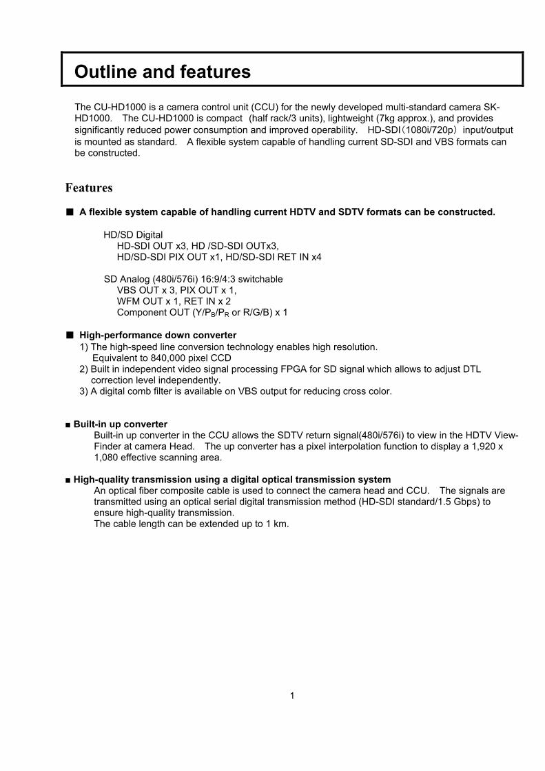
The CU-HD1000 is a camera control unit (CCU) for the newly developed multi-standard camera SK-HD1000. The CU-HD1000 is compact (half rack/3 units), lightweight (7kg approx.), and provides significantly reduced power consumption and improved operability. HD-SDI(1080i/720p) input/output is mounted as standard. A flexible system capable of handling current SD-SDI and VBS formats can be constructed.
Features ■ A flexible system capable of handling current HDTV and SDTV formats can be constructed.
HD/SD Digital
HD-SDI OUT x3, HD /SD-SDI OUTx3, HD/SD-SDI PIX OUT x1, HD/SD-SDI RET IN x4
SD Analog (480i/576i) 16:9/4:3 switchable
VBS OUT x 3, PIX OUT x 1, WFM OUT x 1, RET IN x 2 Component OUT (Y/PB/PR or R/G/B) x 1
■ High-performance down converter
1) The high-speed line conversion technology enables high resolution. Equivalent to 840,000 pixel CCD
2) Built in independent video signal processing FPGA for SD signal which allows to adjust DTL correction level independently.
3) A digital comb filter is available on VBS output for reducing cross color.
■ Built-in up converter Built-in up converter in the CCU allows the SDTV return signal(480i/576i) to view in the HDTV View-Finder at camera Head. The up converter has a pixel interpolation function to display a 1,920 x 1,080 effective scanning area.
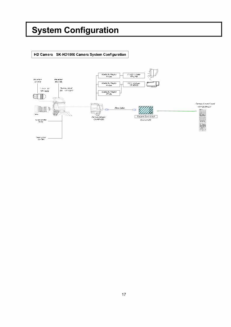
■ High-quality transmission using a digital optical transmission system
An optical fiber composite cable is used to connect the camera head and CCU. The signals are transmitted using an optical serial digital transmission method (HD-SDI standard/1.5 Gbps) to ensure high-quality transmission. The cable length can be extended up to 1 km.
2
Warnings and cautions when using
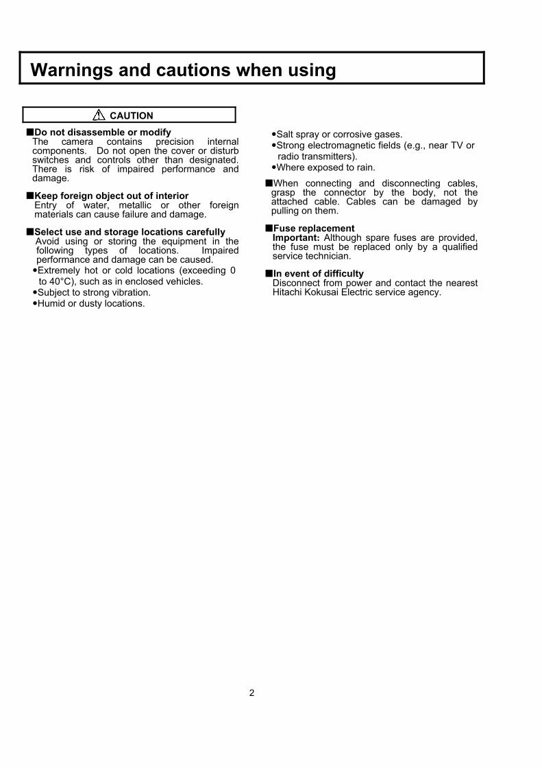
CAUTION
Do not disassemble or modify The camera contains precision internal components. Do not open the cover or disturb switches and controls other than designated. There is risk of impaired performance and damage.
Keep foreign object out of interior Entry of water, metallic or other foreign materials can cause failure and damage.
Select use and storage locations carefully Avoid using or storing the equipment in the following types of locations. Impaired performance and damage can be caused. Extremely hot or cold locations (exceeding 0 to 40°C), such as in enclosed vehicles. Subject to strong vibration. Humid or dusty locations.
Salt spray or corrosive gases. Strong electromagnetic fields (e.g., near TV or radio transmitters). Where exposed to rain.
When connecting and disconnecting cables, grasp the connector by the body, not the attached cable. Cables can be damaged by pulling on them.
Fuse replacement Important: Although spare fuses are provided, the fuse must be replaced only by a qualified service technician.
In event of difficulty Disconnect from power and contact the nearest Hitachi Kokusai Electric service agency.
3
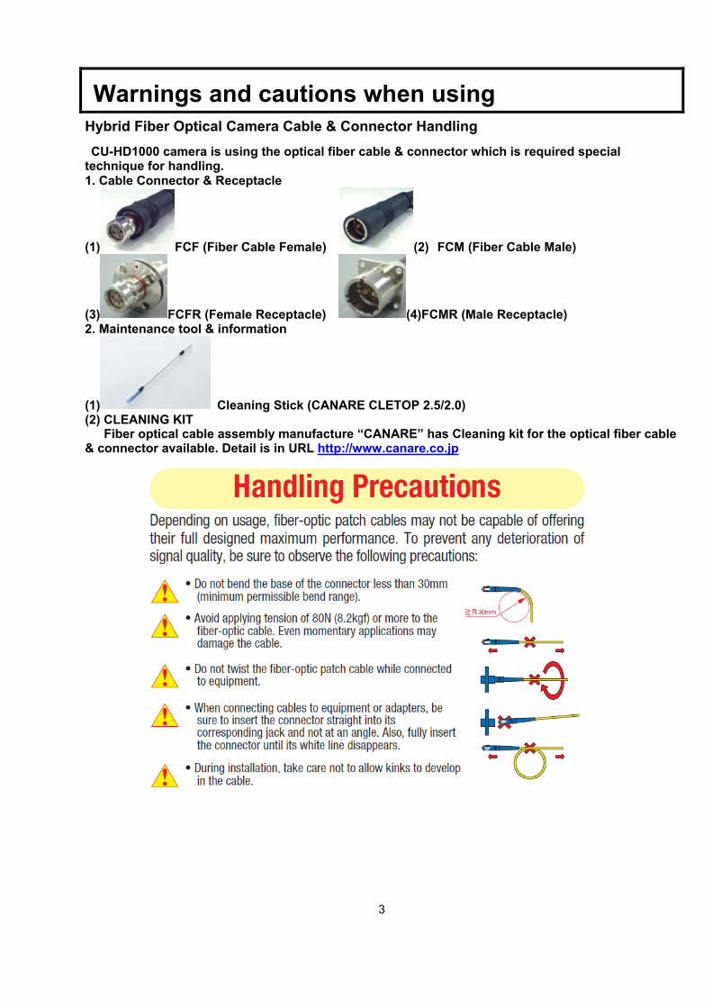
Warnings and cautions when using Hybrid Fiber Optical Camera Cable & Connector Handling CU-HD1000 camera is using the optical fiber cable & connector which is required special
technique for handling. 1. Cable Connector & Receptacle
(1) FCF (Fiber Cable Female) (2) FCM (Fiber Cable Male)
(3) FCFR (Female Receptacle) (4)FCMR (Male Receptacle) 2. Maintenance tool & information
(1) Cleaning Stick (CANARE CLETOP 2.5/2.0) (2) CLEANING KIT Fiber optical cable assembly manufacture “CANARE” has Cleaning kit for the optical fiber cable & connector available. Detail is in URL http://www.canare.co.jp
4
Facility names and functions
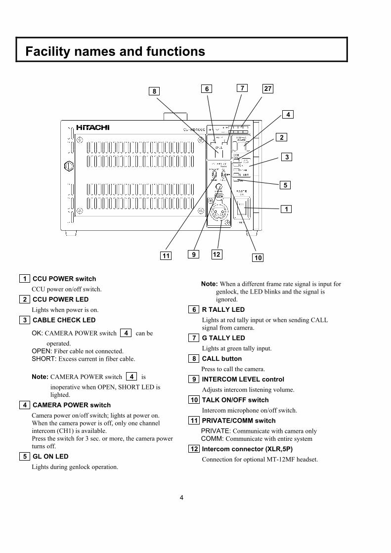
1 CCU POWER switch
CCU power on/off switch. 2 CCU POWER LED
Lights when power is on. 3 CABLE CHECK LED
OK: CAMERA POWER switch 4 can be operated.
OPEN: Fiber cable not connected. SHORT: Excess current in fiber cable. Note: CAMERA POWER switch 4 is
inoperative when OPEN, SHORT LED is lighted.
4 CAMERA POWER switch Camera power on/off switch; lights at power on. When the camera power is off, only one channel intercom (CH1) is available. Press the switch for 3 sec. or more, the camera power turns off.
5 GL ON LED Lights during genlock operation.
Note: When a different frame rate signal is input for
genlock, the LED blinks and the signal is ignored.
6 R TALLY LED Lights at red tally input or when sending CALL signal from camera.
7 G TALLY LED Lights at green tally input.
8 CALL button Press to call the camera. 9 INTERCOM LEVEL control
Adjusts intercom listening volume. 10 TALK ON/OFF switch
Intercom microphone on/off switch. 11 PRIVATE/COMM switch
PRIVATE: Communicate with camera only COMM: Communicate with entire system
12 Intercom connector (XLR,5P) Connection for optional MT-12MF headset.
8 6 7
4
2
3
5
1
1011 12 9
27
5
Facility names and functions
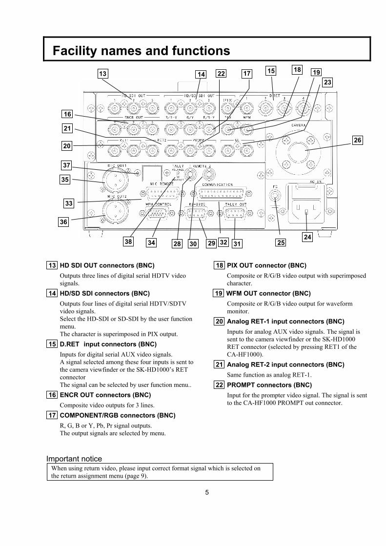
13 HD SDI OUT connectors (BNC)
Outputs three lines of digital serial HDTV video signals.
14 HD/SD SDI connectors (BNC) Outputs four lines of digital serial HDTV/SDTV video signals. Select the HD-SDI or SD-SDI by the user function menu. The character is superimposed in PIX output.
15 D.RET input connectors (BNC) Inputs for digital serial AUX video signals. A signal selected among these four inputs is sent to the camera viewfinder or the SK-HD1000’s RET connector The signal can be selected by user function menu..
16 ENCR OUT connectors (BNC) Composite video outputs for 3 lines.
17 COMPONENT/RGB connectors (BNC) R, G, B or Y, Pb, Pr signal outputs. The output signals are selected by menu.
Important notice
18 PIX OUT connector (BNC) Composite or R/G/B video output with superimposed character.
19 WFM OUT connector (BNC) Composite or R/G/B video output for waveform monitor.
20 Analog RET-1 input connectors (BNC) Inputs for analog AUX video signals. The signal is sent to the camera viewfinder or the SK-HD1000 RET connector (selected by pressing RET1 of the CA-HF1000).
21 Analog RET-2 input connectors (BNC) Same function as analog RET-1.
22 PROMPT connectors (BNC) Input for the prompter video signal. The signal is sent to the CA-HF1000 PROMPT out connector.
When using return video, please input correct format signal which is selected on the return assignment menu (page 9).
14
16
192213 15 17 18
23
26
21
20
35
36
37
33
29 30 24
25 28 31 32 34 38
6
Facility names and functions 23 Genlock connectors (BNC)
Input for tri-level sync signal or black burst signal for genlock operation.
24 AC IN connector Input for AC power supply.
25 FG terminal Frame ground terminal.
26 Fiber connector Connect Fiber cable.
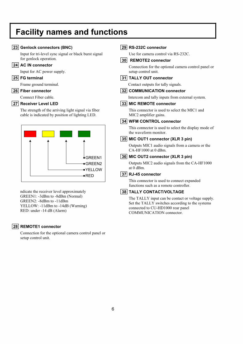
27 Receiver Level LED
The strength of the arriving light signal via fiber cable is indicated by position of lighting LED. ndicate the receiver level approximately GREEN1: -3dBm to -8dBm (Normal) GREEN2: -8dBm to -11dBm YELLOW: -11dBm to -14dB (Warning) RED: under -14 dB (Alarm)
28 REMOTE1 connector Connection for the optional camera control panel or setup control unit.
29 RS-232C connector Use for camera control via RS-232C.
30 REMOTE2 connector Connection for the optional camera control panel or setup control unit.
31 TALLY OUT connector Contact outputs for tally signals.
32 COMMUNICATION connector Intercom and tally inputs from external system.
33 MIC REMOTE connector This connector is used to select the MIC1 and MIC2 amplifier gains.
34 WFM CONTROL connector This connector is used to select the display mode of the waveform monitor.
35 MIC OUT1 connector (XLR 3 pin) Outputs MIC1 audio signals from a camera or the CA-HF1000 at 0 dBm.
36 MIC OUT2 connector (XLR 3 pin) Outputs MIC2 audio signals from the CA-HF1000 at 0 dBm.
37 RJ-45 connector This connector is used to connect expanded functions such as a remote controller.
38 TALLY CONTACT/VOLTAGE The TALLY input can be contact or voltage supply. Set the TALLY switches according to the systems connected to CU-HD1000 rear panel COMMUNICATION connector.
GREEN1GREEN2YELLOWRED
7
Function menu Function menu
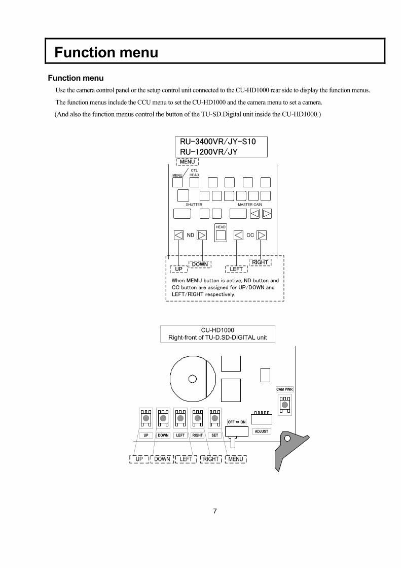
Use the camera control panel or the setup control unit connected to the CU-HD1000 rear side to display the function menus.
The function menus include the CCU menu to set the CU-HD1000 and the camera menu to set a camera.
(And also the function menus control the button of the TU-SD.Digital unit inside the CU-HD1000.)
ND CC
HEAD
MENU
CTLHEAD
MASTER CAINSHUTTER
UPDOWN
LEFTRIGHT
MENU
RU-3400VR/JY-S10 RU-1200VR/JY
When MEMU button is active, ND button and CC button are assigned for UP/DOWN and LEFT/RIGHT respectively.
UP DOWN LEFT RIGHT SETADJUST
OFF ⇔ ON
CAM PWR
MENURIGHTLEFTDOWNUP
CU-HD1000Right-front of TU-D.SD-DIGITAL unit
8
Function menu
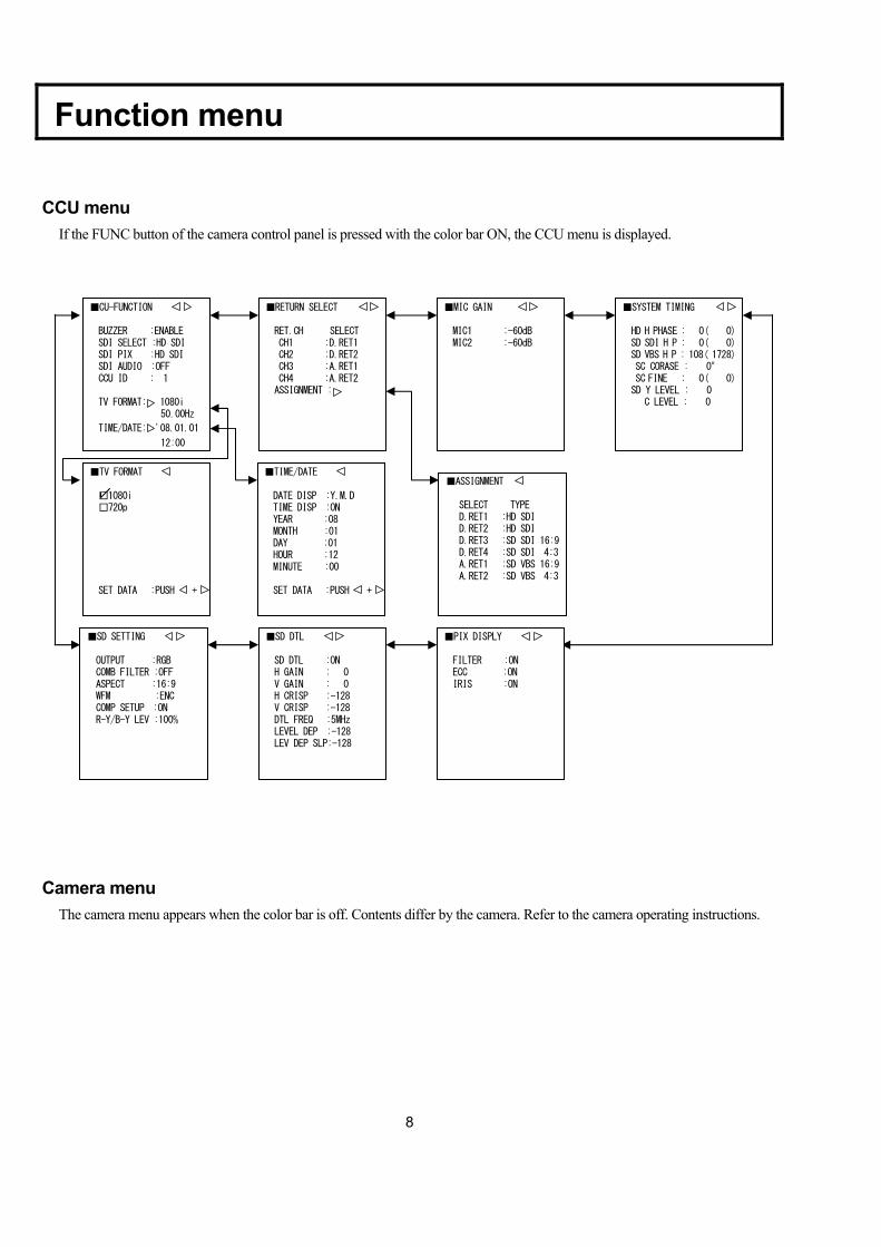
CCU menu If the FUNC button of the camera control panel is pressed with the color bar ON, the CCU menu is displayed.
Camera menu
The camera menu appears when the color bar is off. Contents differ by the camera. Refer to the camera operating instructions.
■RETURN SELECT RET.CH SELECT CH1 :D.RET1 CH2 :D.RET2 CH3 :A.RET1 CH4 :A.RET2 ASSIGNMENT :
■ASSIGNMENT SELECT TYPE D.RET1 :HD SDI D.RET2 :HD SDI D.RET3 :SD SDI 16:9 D.RET4 :SD SDI 4:3 A.RET1 :SD VBS 16:9 A.RET2 :SD VBS 4:3
■MIC GAIN MIC1 :-60dB MIC2 :-60dB
■SYSTEM TIMING HD H PHASE : 0( 0) SD SDI H P : 0( 0) SD VBS H P : 108( 1728) SC CORASE : 0° SC FINE : 0( 0) SD Y LEVEL : 0 C LEVEL : 0
■SD SETTING OUTPUT :RGB COMB FILTER :OFF ASPECT :16:9 WFM :ENC COMP SETUP :ON R-Y/B-Y LEV :100%
■SD DTL SD DTL :ON H GAIN : 0 V GAIN : 0 H CRISP :-128 V CRISP :-128 DTL FREQ :5MHz LEVEL DEP :-128 LEV DEP SLP:-128
■PIX DISPLY FILTER :ON ECC :ON IRIS :ON
■TIME/DATE DATE DISP :Y.M.D TIME DISP :ON YEAR :08 MONTH :01 DAY :01 HOUR :12 MINUTE :00 SET DATA :PUSH +
■TV FORMAT □1080i □720p SET DATA :PUSH +
■CU-FUNCTION BUZZER :ENABLE SDI SELECT :HD SDI SDI PIX :HD SDI SDI AUDIO :OFF CCU ID : 1 TV FORMAT: 1080i 50.00Hz
TIME/DATE: '08.01.01
12:00
9
Function menu CU-FUNCTION menu
TV FORMAT menu
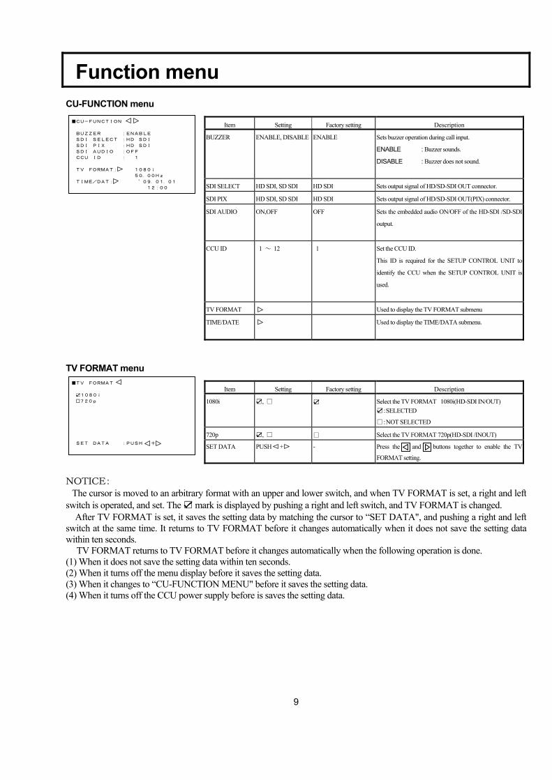
NOTICE: The cursor is moved to an arbitrary format with an upper and lower switch, and when TV FORMAT is set, a right and left switch is operated, and set. The ☑ mark is displayed by pushing a right and left switch, and TV FORMAT is changed.
After TV FORMAT is set, it saves the setting data by matching the cursor to “SET DATA", and pushing a right and left switch at the same time. It returns to TV FORMAT before it changes automatically when it does not save the setting data within ten seconds. TV FORMAT returns to TV FORMAT before it changes automatically when the following operation is done. (1) When it does not save the setting data within ten seconds. (2) When it turns off the menu display before it saves the setting data. (3) When it changes to “CU-FUNCTION MENU" before it saves the setting data. (4) When it turns off the CCU power supply before is saves the setting data.
■CU-FUNCTION
BUZZER :ENABLE
SDI SELECT :HD SDI
SDI PIX :HD SDI
SDI AUDIO :OFF
CCU ID : 1
TV FORMAT: 1080i
50.00Hz
TIME/DAT: ’09.01.01
12:00
Item Setting Factory setting Description
BUZZER ENABLE, DISABLE ENABLE Sets buzzer operation during call input.
ENABLE : Buzzer sounds.
DISABLE : Buzzer does not sound.
SDI SELECT HD SDI, SD SDI HD SDI Sets output signal of HD/SD-SDI OUT connector.
SDI PIX HD SDI, SD SDI HD SDI Sets output signal of HD/SD-SDI OUT(PIX) connector.
SDI AUDIO ON,OFF OFF Sets the embedded audio ON/OFF of the HD-SDI /SD-SDI
output.
CCU ID 1 ~ 12 1 Set the CCU ID.
This ID is required for the SETUP CONTROL UNIT to
identify the CCU when the SETUP CONTROL UNIT is
used.
TV FORMAT Used to display the TV FORMAT submenu
TIME/DATE Used to display the TIME/DATA submenu.
■TV FORMAT
☑1080i
□720p
SET DATA :PUSH +
Item Setting Factory setting Description
1080i ☑, □ ☑ Select the TV FORMAT 1080i(HD-SDI IN/OUT) ☑:SELECTED
□:NOT SELECTED
720p ☑, □ □ Select the TV FORMAT 720p(HD-SDI /INOUT)
SET DATA PUSH +
- Press the and buttons together to enable the TV
FORMAT setting.
10
Function menu
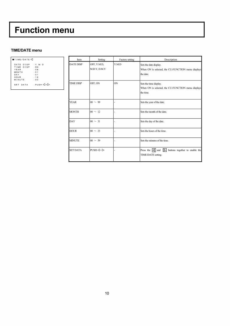
TIME/DATE menu
■TIME/DATE
DATE DISP :Y.M.D
TIME DISP :ON
YEAR :08
MONTH :01
DAY :01
HOUR :12
MINUTE :00
SET DATA :PUSH +
Item Setting Factory setting Description DATE DISP OFF, Y.M.D,
M.D.Y, D.M.Y
Y.M.D Sets the date display.
When ON is selected, the CU-FUNCTION menu displays
the date.
TIME DISP OFF, ON ON Sets the time display. When ON is selected, the CU-FUNCTION menu displays
the time.
YEAR 00 ~ 99 - Sets the year of the date.
MONTH 00 ~ 12 - Sets the month of the date.
DAY 00 ~ 31 - Sets the day of the date.
HOUR 00 ~ 23 - Sets the hours of the time.
MINUTE 00 ~ 59 - Sets the minutes of the time.
SET DATA PUSH +
- Press the and buttons together to enable the
TIME/DATE setting.
11
Function menu
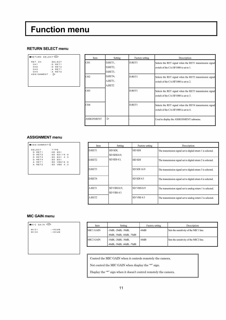
RETURN SELECT menu
ASSIGNMENT menu
MIC GAIN menu
■RETURN SELECT
RET.CH SELECT
CH1 :D.RET1
CH2 :D.RET2
CH3 :A.RET1
CH4 :A.RET2
ASSIGNMENT :
■ASSIGNMENT
SELECT TYPE
D.RET1 :HD SDI
D.RET2 :SD SDI16:9
D.RET3 :SD SDI 4:3
D.RET4 :SD SDI
A.RET1 :SD VBS16:9
A.RET2 :SD VBS 4:3
Item Setting Factory setting Description D.RET1 HD SDI The transmission signal set to digital return 1 is selected.
D.RET2 HD SDI The transmission signal set to digital return 2 is selected.
D.RET3 SD SDI 16:9 The transmission signal set to digital return 3 is selected.
D.RET4
HD SDI,
SD SDI16:9,
SD SDI 4:3,
SD SDI 4:3 The transmission signal set to digital return 4 is selected.
A.RET1 SD VBS16:9 The transmission signal set to analog return 1 is selected.
A.RET2
SD VBS16:9,
SD VBS 4:3
SD VBS 4:3 The transmission signal set to analog return 2 is selected.
Item Setting Factory setting Description MIC1 GAIN -10dB, -20dB, -30dB,
-40dB, -50dB, -60dB, -70dB
-60dB Sets the sensitivity of the MIC1 line.
MIC2 GAIN -10dB, -20dB, -30dB,
-40dB, -50dB, -60dB, -70dB
-60dB Sets the sensitivity of the MIC2 line.
Control the MIC GAIN when it controls remotely the camera.
Not control the MIC GAIN when display the “*” sign.
Display the “*” sign when it doesn’t control remotely the camera.
Item Setting Factory setting Description CH1 D.RET1 Selects the RET signal when the RET1 transmission signal
switch of the CA-HF1000 is set to 1.
CH2 D.RET1 Selects the RET signal when the RET2 transmission signal
switch of the CA-HF1000 is set to 2.
CH3 D.RET1 Selects the RET signal when the RET3 transmission signal
switch of the CA-HF1000 is set to 3.
CH4
D,RET1,
D,RET2,
D,RET3,
D,RET4,
A,RET1,
A,RET2
D.RET1 Selects the RET signal when the RET4 transmission signal
switch of the CA-HF1000 is set to 4.
ASSIGNMENT - Used to display the ASSIGNMENT submenu.
■MIC GAIN
MIC1 :-60dB
MIC2 :-60dB
12
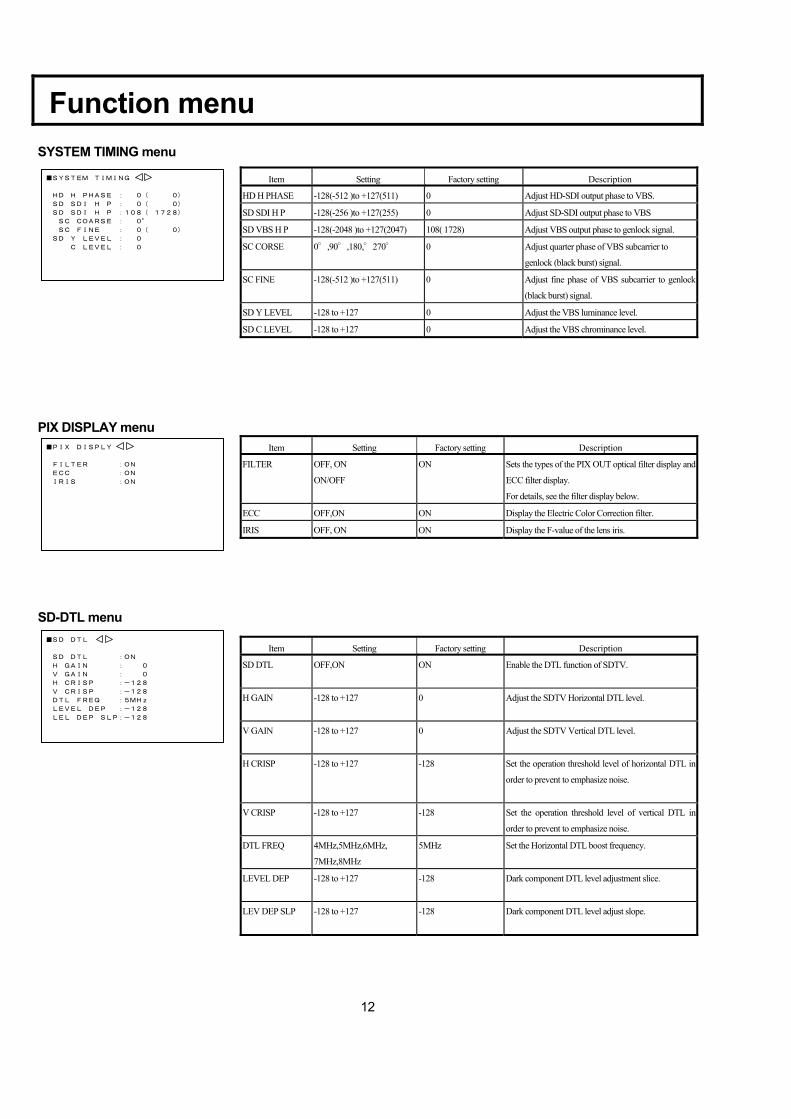
Function menu SYSTEM TIMING menu
PIX DISPLAY menu
SD-DTL menu
■SD DTL
SD DTL :ON
H GAIN : 0
V GAIN : 0
H CRISP :-128
V CRISP :-128
DTL FREQ :5MHz
LEVEL DEP :-128
LEL DEP SLP:-128
Item Setting Factory setting Description SD DTL OFF,ON ON Enable the DTL function of SDTV.
H GAIN -128 to +127 0 Adjust the SDTV Horizontal DTL level.
V GAIN -128 to +127 0 Adjust the SDTV Vertical DTL level.
H CRISP -128 to +127 -128 Set the operation threshold level of horizontal DTL in
order to prevent to emphasize noise.
V CRISP -128 to +127 -128
Set the operation threshold level of vertical DTL in
order to prevent to emphasize noise.
DTL FREQ 4MHz,5MHz,6MHz,
7MHz,8MHz
5MHz Set the Horizontal DTL boost frequency.
LEVEL DEP -128 to +127 -128 Dark component DTL level adjustment slice.
LEV DEP SLP -128 to +127 -128 Dark component DTL level adjust slope.
■SYSTEM TIMING
HD H PHASE : 0( 0)
SD SDI H P : 0( 0)
SD SDI H P :108( 1728)
SC COARSE : 0°
SC FINE : 0( 0)
SD Y LEVEL : 0
C LEVEL : 0
Item Setting Factory setting Description HD H PHASE -128(-512 )to +127(511) 0 Adjust HD-SDI output phase to VBS.
SD SDI H P -128(-256 )to +127(255) 0 Adjust SD-SDI output phase to VBS
SD VBS H P -128(-2048 )to +127(2047) 108( 1728) Adjust VBS output phase to genlock signal.
SC CORSE 0°,90°,180,°270° 0 Adjust quarter phase of VBS subcarrier to
genlock (black burst) signal.
SC FINE -128(-512 )to +127(511) 0 Adjust fine phase of VBS subcarrier to genlock
(black burst) signal.
SD Y LEVEL -128 to +127 0 Adjust the VBS luminance level.
SD C LEVEL -128 to +127 0 Adjust the VBS chrominance level.
■PIX DISPLY
FILTER :ON
ECC :ON
IRIS :ON
Item Setting Factory setting Description FILTER OFF, ON
ON/OFF
ON Sets the types of the PIX OUT optical filter display and
ECC filter display.
For details, see the filter display below.
ECC OFF,ON ON Display the Electric Color Correction filter.
IRIS OFF, ON ON Display the F-value of the lens iris.
13
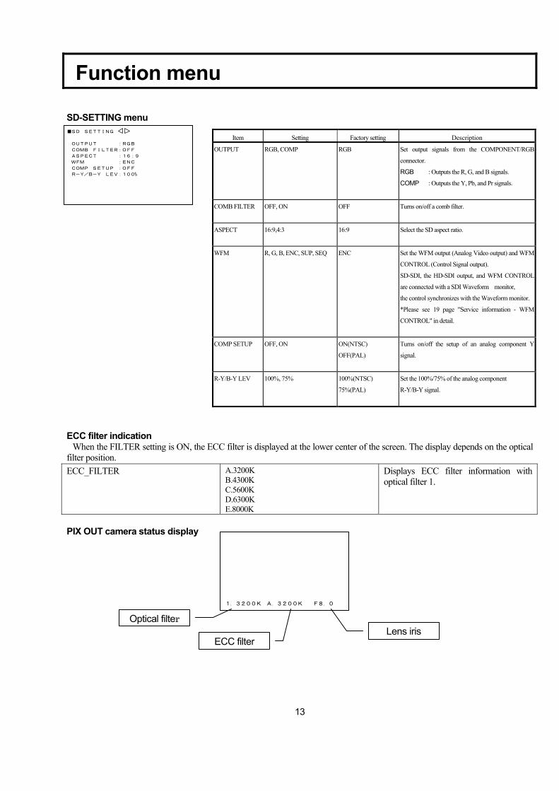
Function menu SD-SETTING menu
ECC filter indication When the FILTER setting is ON, the ECC filter is displayed at the lower center of the screen. The display depends on the optical filter position. ECC_FILTER A.3200K
B.4300K C.5600K D.6300K E.8000K
Displays ECC filter information with optical filter 1.
PIX OUT camera status display
1.3200K A.3200K F8.0
Optical filter
ECC filter Lens iris
■SD SETTING
OUTPUT :RGB
COMB FILTER:OFF
ASPECT :16:9
WFM :ENC
COMP SETUP :OFF
R-Y/B-Y LEV:100%
Item Setting Factory setting Description OUTPUT RGB, COMP RGB Set output signals from the COMPONENT/RGB
connector.
RGB : Outputs the R, G, and B signals.
COMP : Outputs the Y, Pb, and Pr signals.
COMB FILTER OFF, ON OFF Turns on/off a comb filter.
ASPECT 16:9,4:3 16:9 Select the SD aspect ratio.
WFM R, G, B, ENC, SUP, SEQ ENC Set the WFM output (Analog Video output) and WFM
CONTROL (Control Signal output).
SD-SDI, the HD-SDI output, and WFM CONTROL
are connected with a SDI Waveform monitor,
the control synchronizes with the Waveform monitor.
*Please see 19 page "Service information - WFM
CONTROL" in detail.
COMP SETUP OFF, ON ON(NTSC)
OFF(PAL)
Turns on/off the setup of an analog component Y
signal.
R-Y/B-Y LEV 100%, 75% 100%(NTSC)
75%(PAL)
Set the 100%/75% of the analog component
R-Y/B-Y signal.
14
Cable check
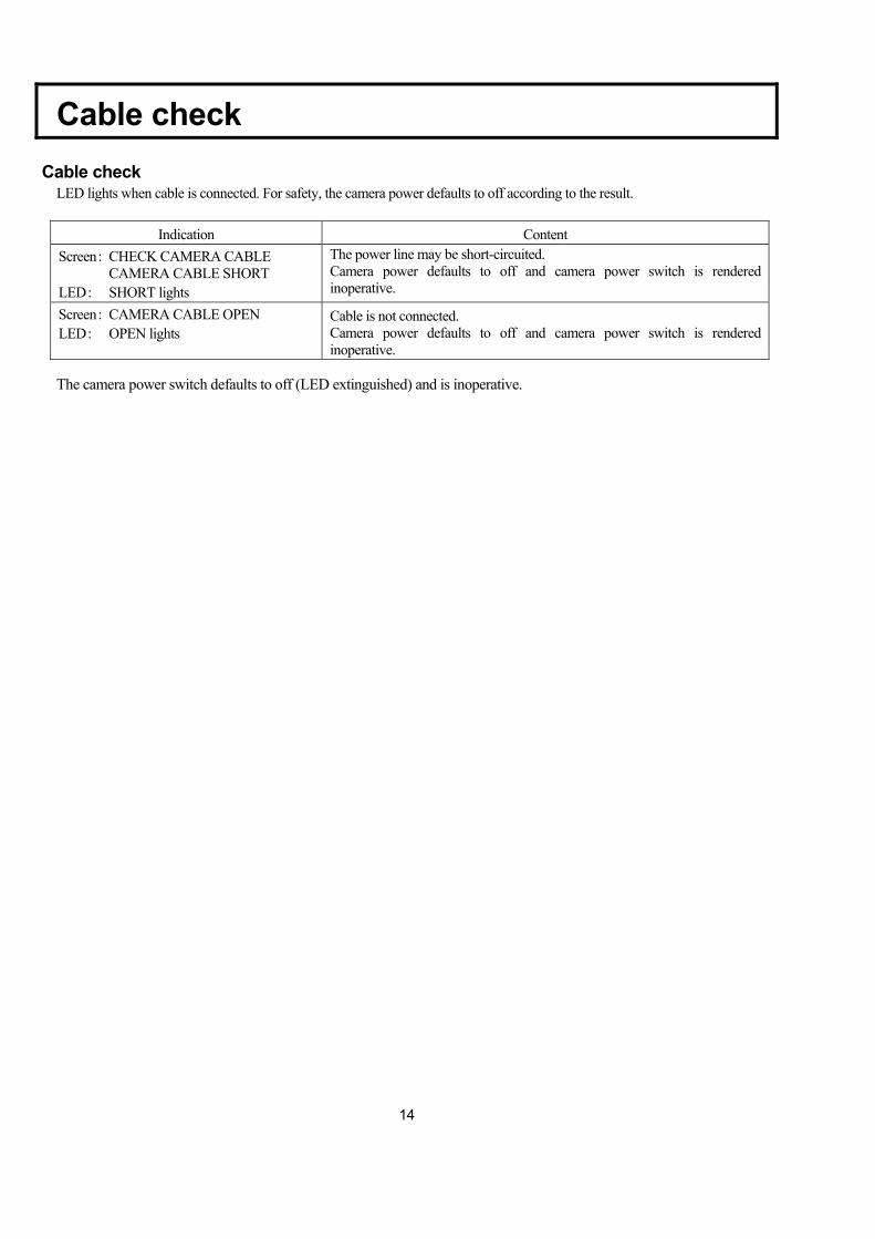
Cable check
LED lights when cable is connected. For safety, the camera power defaults to off according to the result.
Indication Content Screen: CHECK CAMERA CABLE CAMERA CABLE SHORT LED: SHORT lights
The power line may be short-circuited. Camera power defaults to off and camera power switch is rendered inoperative.
Screen: CAMERA CABLE OPEN LED: OPEN lights
Cable is not connected. Camera power defaults to off and camera power switch is rendered inoperative.
The camera power switch defaults to off (LED extinguished) and is inoperative.

15
Warning indication
Indication Content Screen: CCU FAN ALARM!! FAN warning of CCU
The internal fan is stopped or the rotating speed is lowered.
If the fan alarm is indicated, the system should be repaired immediately.
16
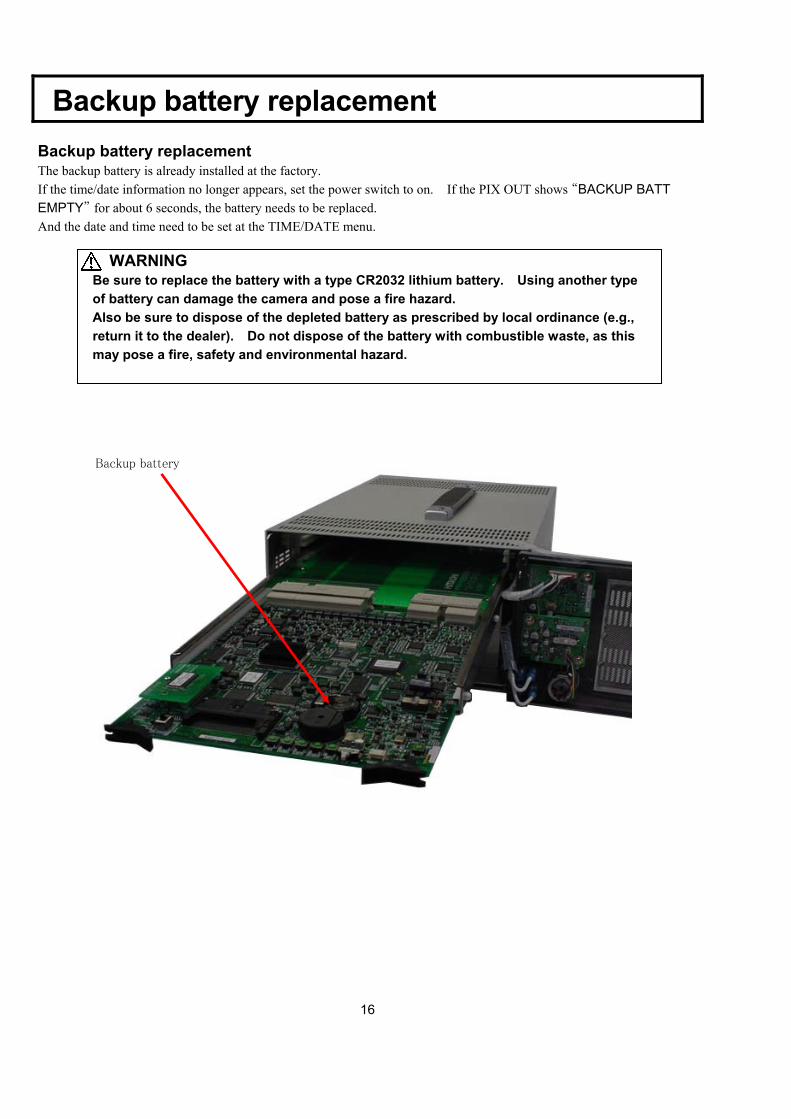
Backup battery replacement
Backup battery replacement The backup battery is already installed at the factory. If the time/date information no longer appears, set the power switch to on. If the PIX OUT shows “BACKUP BATT EMPTY” for about 6 seconds, the battery needs to be replaced. And the date and time need to be set at the TIME/DATE menu.
WARNING Be sure to replace the battery with a type CR2032 lithium battery. Using another type of battery can damage the camera and pose a fire hazard. Also be sure to dispose of the depleted battery as prescribed by local ordinance (e.g., return it to the dealer). Do not dispose of the battery with combustible waste, as this may pose a fire, safety and environmental hazard.
Backup battery
17
System Configuration
18
PUSH
12
3
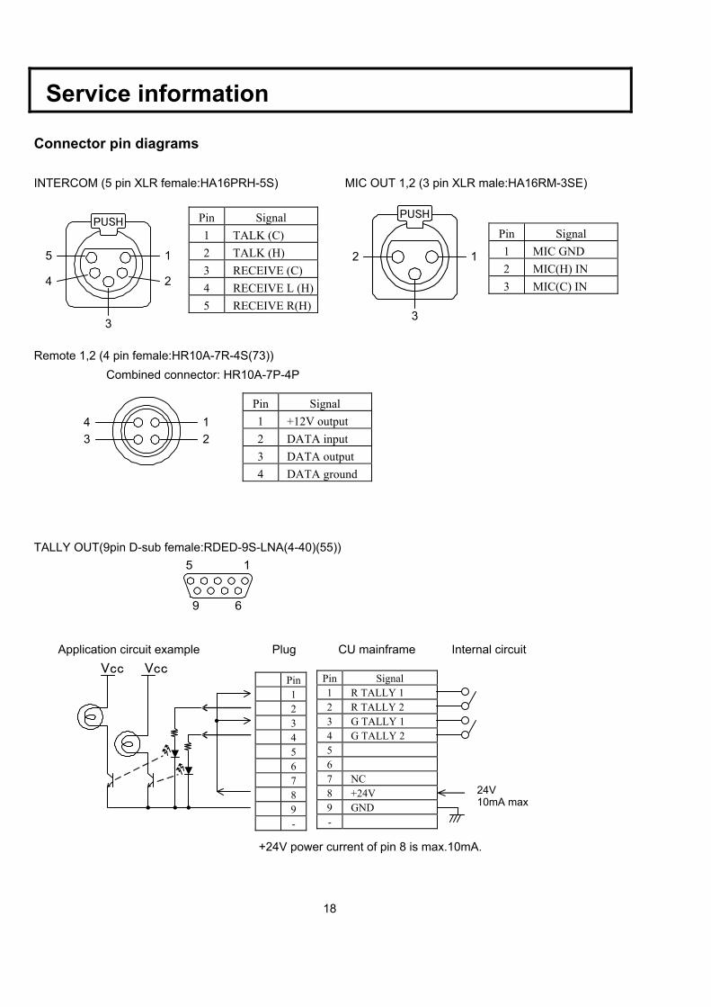
Service information Connector pin diagrams INTERCOM (5 pin XLR female:HA16PRH-5S) MIC OUT 1,2 (3 pin XLR male:HA16RM-3SE)
Remote 1,2 (4 pin female:HR10A-7R-4S(73)) Combined connector: HR10A-7P-4P
TALLY OUT(9pin D-sub female:RDED-9S-LNA(4-40)(55))
15
9 6 Application circuit example Plug CU mainframe Internal circuit
Pin Signal 1 TALK (C) 2 TALK (H) 3 RECEIVE (C) 4 RECEIVE L (H)5 RECEIVE R(H)
Pin Signal 1 MIC GND 2 MIC(H) IN 3 MIC(C) IN
Pin Signal 1 +12V output 2 DATA input 3 DATA output 4 DATA ground
Pin Signal 1 R TALLY 1 2 R TALLY 2 3 G TALLY 1 4 G TALLY 2 5 6 7 NC 8 +24V 9 GND -
Pin 1 2 3 4 5 6 7 8 9 -
PUSH
15
3
4 2
123
4
24V10mA max
+24V power current of pin 8 is max.10mA.
Vcc Vcc
19
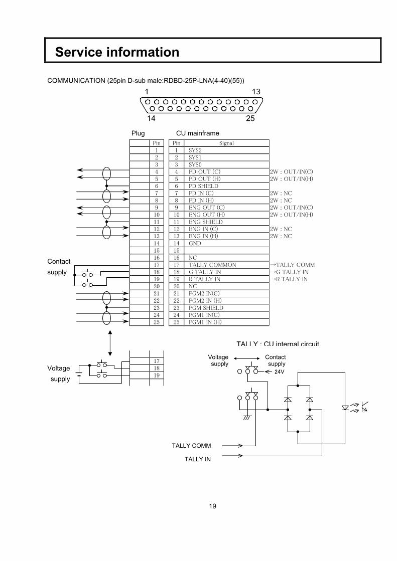
Service information COMMUNICATION (25pin D-sub male:RDBD-25P-LNA(4-40)(55))
1 13
14 25
Plug CU mainframe Contact supply
Voltage
supply
Pin 1 2 3 4 5 6 7 8 9 10 11 12 13 14 15 16 17 18 19 20 21 22 23 24 25
Pin Signal 1 SYS2 2 SYS1 3 SYS0 4 PD OUT (C) 2W : OUT/IN(C) 5 PD OUT (H) 2W : OUT/IN(H) 6 PD SHIELD 7 PD IN (C) 2W : NC 8 PD IN (H) 2W : NC 9 ENG OUT (C) 2W : OUT/IN(C) 10 ENG OUT (H) 2W : OUT/IN(H) 11 ENG SHIELD 12 ENG IN (C) 2W : NC 13 ENG IN (H) 2W : NC 14 GND 15 16 NC 17 TALLY COMMON →TALLY COMM 18 G TALLY IN →G TALLY IN 19 R TALLY IN →R TALLY IN 20 NC 21 PGM2 IN(C) 22 PGM2 IN (H) 23 PGM SHIELD 24 PGM1 IN(C) 25 PGM1 IN (H)
17 18 19
TALLY COMM
Contact supply
Voltage supply
TALLY IN
24V
TALLY ; CU internal circuit
20
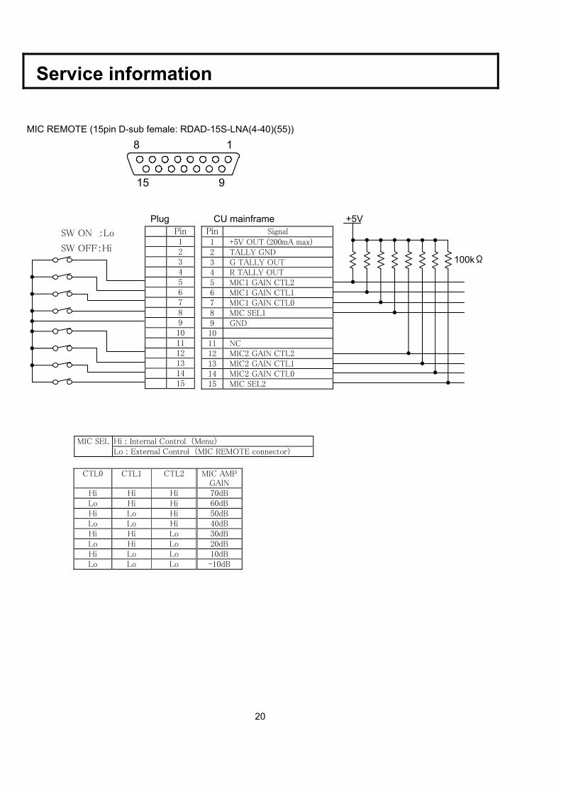
Service information MIC REMOTE (15pin D-sub female: RDAD-15S-LNA(4-40)(55))
8 1
15 9
Plug CU mainframe +5V SW ON :Lo SW OFF:Hi
Hi : Internal Control (Menu) MIC SEL Lo : External Control (MIC REMOTE connector)
Pin 1 2 3 4 5 6 7 8 9 10 11 12 13 14 15
Pin Signal 1 +5V OUT (200mA max) 2 TALLY GND 3 G TALLY OUT 4 R TALLY OUT 5 MIC1 GAIN CTL2 6 MIC1 GAIN CTL1 7 MIC1 GAIN CTL0 8 MIC SEL1 9 GND 10 11 NC 12 MIC2 GAIN CTL2 13 MIC2 GAIN CTL1 14 MIC2 GAIN CTL0 15 MIC SEL2
CTL0 CTL1 CTL2 MIC AMP GAIN
Hi Hi Hi 70dB Lo Hi Hi 60dB Hi Lo Hi 50dB Lo Lo Hi 40dB Hi Hi Lo 30dB Lo Hi Lo 20dB Hi Lo Lo 10dB Lo Lo Lo -10dB
100kΩ
21
5 1
11
610
15
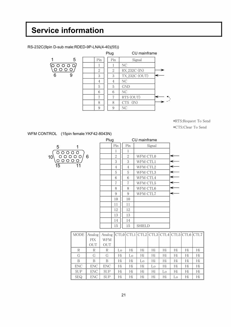
Service information RS-232C(9pin D-sub male:RDED-9P-LNA(4-40)(55)) Plug CU mainframe
51
6 9
*RTS:Request To Send
*CTS:Clear To Send
WFM CONTROL (15pin female:YKF42-8043N) Plug CU mainframe
Pin Signal
1 NC
2 RX_232C (IN)
3 TX_232C (OUT)
4 NC
5 GND
6 NC
7 RTS (OUT)
8 CTS (IN)
9 NC
Pin
1
2
3
4
5
6
7
8
9
Pin Signal
1
2 WFM CTL0
3 WFM CTL1
4 WFM CTL2
5 WFM CTL3
6 WFM CTL4
7 WFM CTL5
8 WFM CTL6
9 WFM CTL7
10
11
12
13
14
15 SHIELD
Pin
1
2
3
4
5
6
7
8
9
10
11
12
13
14
15
MODE Analog
PIX
OUT
Analog
WFM
OUT
CTL0 CTL1 CTL2 CTL3 CTL4 CTL5 CTL6 CTL7
R R R Lo Hi Hi Hi Hi Hi Hi Hi
G G G Hi Lo Hi Hi Hi Hi Hi Hi
B B B Hi Hi Lo Hi Hi Hi Hi Hi
ENC ENC ENC Hi Hi Hi Lo Hi Hi Hi Hi
SUP ENC SUP Hi Hi Hi Hi Lo Hi Hi Hi
SEQ ENC SUP Hi Hi Hi Hi Hi Lo Hi Hi
22
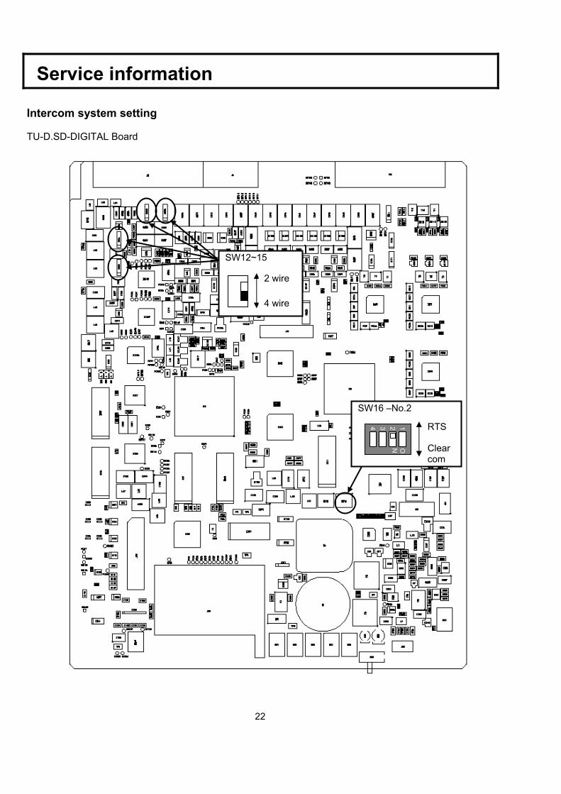
Service information Intercom system setting TU-D.SD-DIGITAL Board
SW12~15
2 wire
4 wire
SW16 –No.2
1234
ON
RTS
Clear com
23
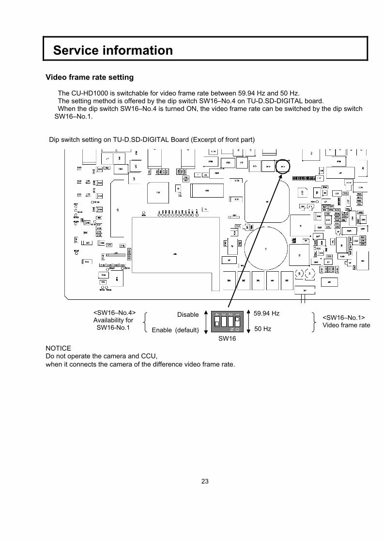
Service information Video frame rate setting
The CU-HD1000 is switchable for video frame rate between 59.94 Hz and 50 Hz. The setting method is offered by the dip switch SW16–No.4 on TU-D.SD-DIGITAL board. When the dip switch SW16–No.4 is turned ON, the video frame rate can be switched by the dip switch
SW16–No.1. Dip switch setting on TU-D.SD-DIGITAL Board (Excerpt of front part)
NOTICE Do not operate the camera and CCU, when it connects the camera of the difference video frame rate.
1 2 3 4
ON
59.94 Hz
SW16 50 Hz
<SW16–No.1> Video frame rate
Disable
Enable (default)
<SW16–No.4> Availability for SW16-No.1
24
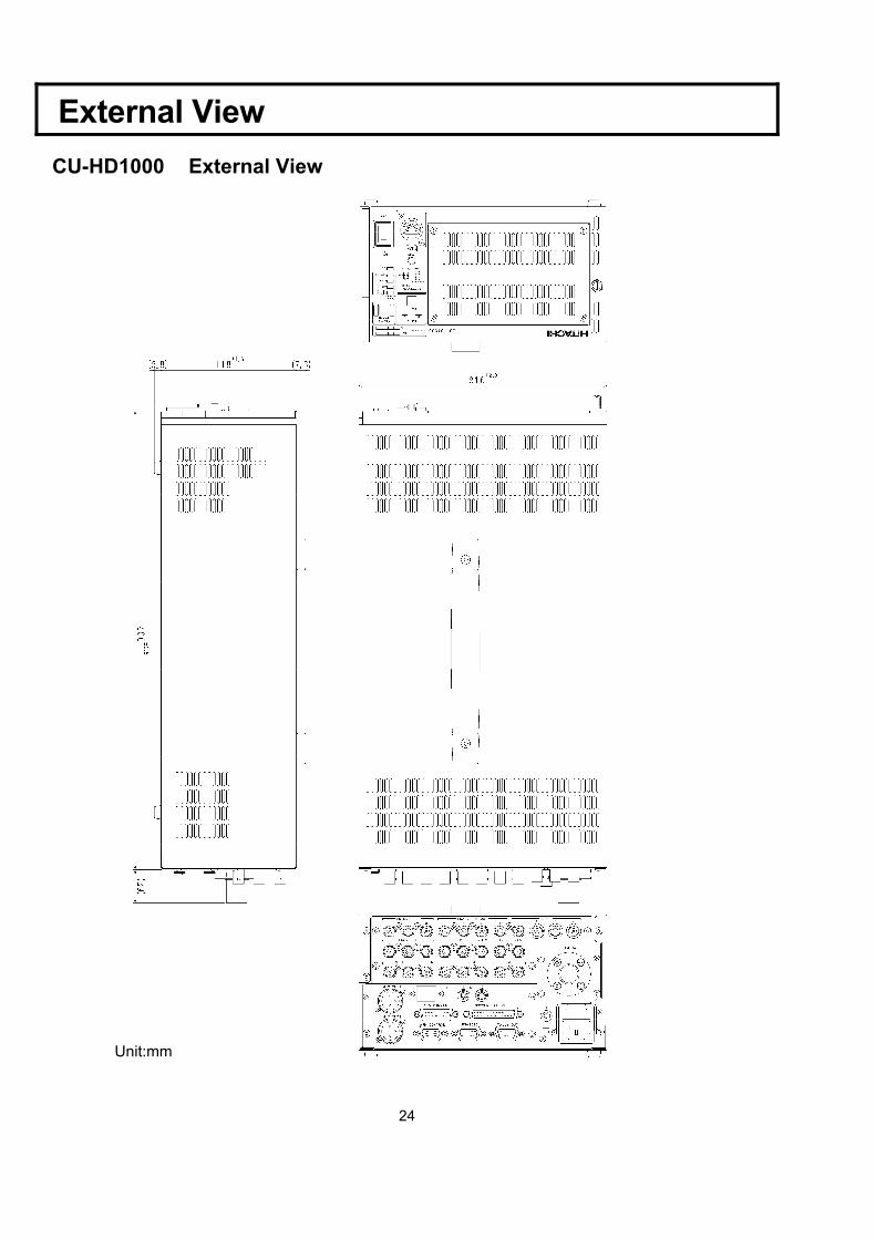
External View
CU-HD1000 External View
Unit:mm
25
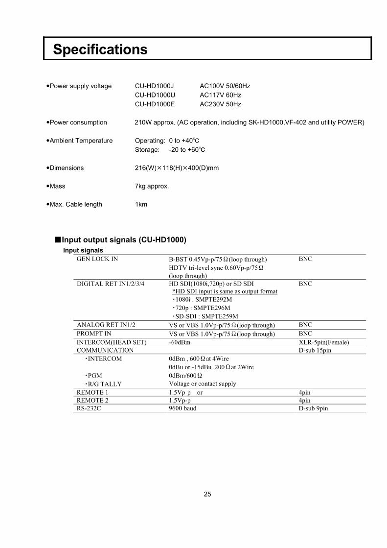
Specifications
Power supply voltage CU-HD1000J AC100V 50/60Hz CU-HD1000U AC117V 60Hz CU-HD1000E AC230V 50Hz
Power consumption 210W approx. (AC operation, including SK-HD1000,VF-402 and utility POWER)
Ambient Temperature Operating: 0 to +40℃ Storage: -20 to +60℃
Dimensions 216(W) 118(H) 400(D)mm
Mass 7kg approx.
Max. Cable length 1km
■Input output signals (CU-HD1000) Input signals
GEN LOCK IN B-BST 0.45Vp-p/75Ω(loop through) HDTV tri-level sync 0.60Vp-p/75Ω (loop through)
BNC
DIGITAL RET IN1/2/3/4 HD SDI(1080i,720p) or SD SDI *HD SDI input is same as output format ・1080i : SMPTE292M ・720p : SMPTE296M ・SD-SDI : SMPTE259M
BNC
ANALOG RET IN1/2 VS or VBS 1.0Vp-p/75Ω(loop through) BNC PROMPT IN VS or VBS 1.0Vp-p/75Ω(loop through) BNC INTERCOM(HEAD SET) -60dBm XLR-5pin(Female) COMMUNICATION D-sub 15pin
・INTERCOM 0dBm , 600Ωat 4Wire 0dBu or -15dBu ,200Ωat 2Wire
・PGM 0dBm/600Ω ・R/G TALLY Voltage or contact supply
REMOTE 1 1.5Vp-p or 4pin REMOTE 2 1.5Vp-p 4pin RS-232C 9600 baud D-sub 9pin
26
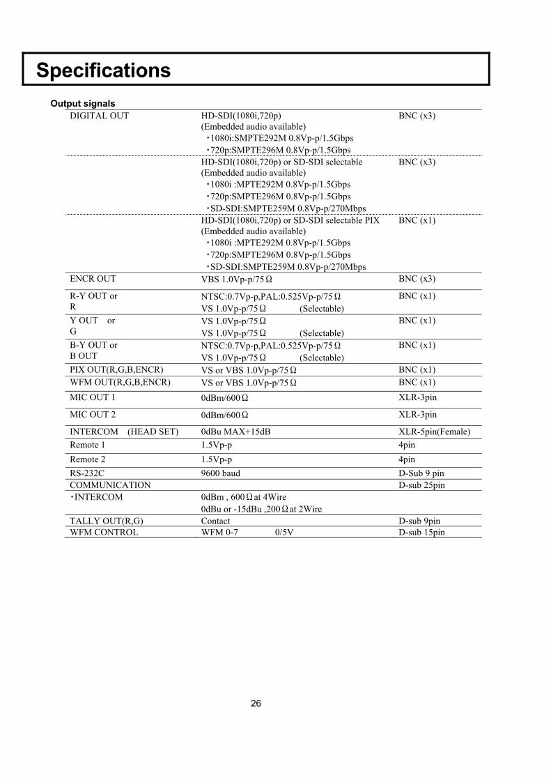
Specifications
Output signals
DIGITAL OUT HD-SDI(1080i,720p) (Embedded audio available) ・1080i:SMPTE292M 0.8Vp-p/1.5Gbps ・720p:SMPTE296M 0.8Vp-p/1.5Gbps
BNC (x3)
HD-SDI(1080i,720p) or SD-SDI selectable (Embedded audio available) ・1080i :MPTE292M 0.8Vp-p/1.5Gbps ・720p:SMPTE296M 0.8Vp-p/1.5Gbps ・SD-SDI:SMPTE259M 0.8Vp-p/270Mbps
BNC (x3)
HD-SDI(1080i,720p) or SD-SDI selectable PIX (Embedded audio available) ・1080i :MPTE292M 0.8Vp-p/1.5Gbps ・720p:SMPTE296M 0.8Vp-p/1.5Gbps ・SD-SDI:SMPTE259M 0.8Vp-p/270Mbps
BNC (x1)
ENCR OUT VBS 1.0Vp-p/75Ω BNC (x3)
R-Y OUT or R
NTSC:0.7Vp-p,PAL:0.525Vp-p/75Ω VS 1.0Vp-p/75Ω (Selectable)
BNC (x1)
Y OUT or G
VS 1.0Vp-p/75Ω VS 1.0Vp-p/75Ω (Selectable)
BNC (x1)
B-Y OUT or B OUT
NTSC:0.7Vp-p,PAL:0.525Vp-p/75Ω VS 1.0Vp-p/75Ω (Selectable)
BNC (x1)
PIX OUT(R,G,B,ENCR) VS or VBS 1.0Vp-p/75Ω BNC (x1) WFM OUT(R,G,B,ENCR) VS or VBS 1.0Vp-p/75Ω BNC (x1) MIC OUT 1 0dBm/600Ω XLR-3pin
MIC OUT 2 0dBm/600Ω XLR-3pin
INTERCOM (HEAD SET) 0dBu MAX+15dB XLR-5pin(Female) Remote 1 1.5Vp-p 4pin Remote 2 1.5Vp-p 4pin RS-232C 9600 baud D-Sub 9 pin COMMUNICATION D-sub 25pin ・INTERCOM 0dBm , 600Ωat 4Wire
0dBu or -15dBu ,200Ωat 2Wire
TALLY OUT(R,G) Contact D-sub 9pin WFM CONTROL WFM 0-7 0/5V D-sub 15pin
27
Specifications
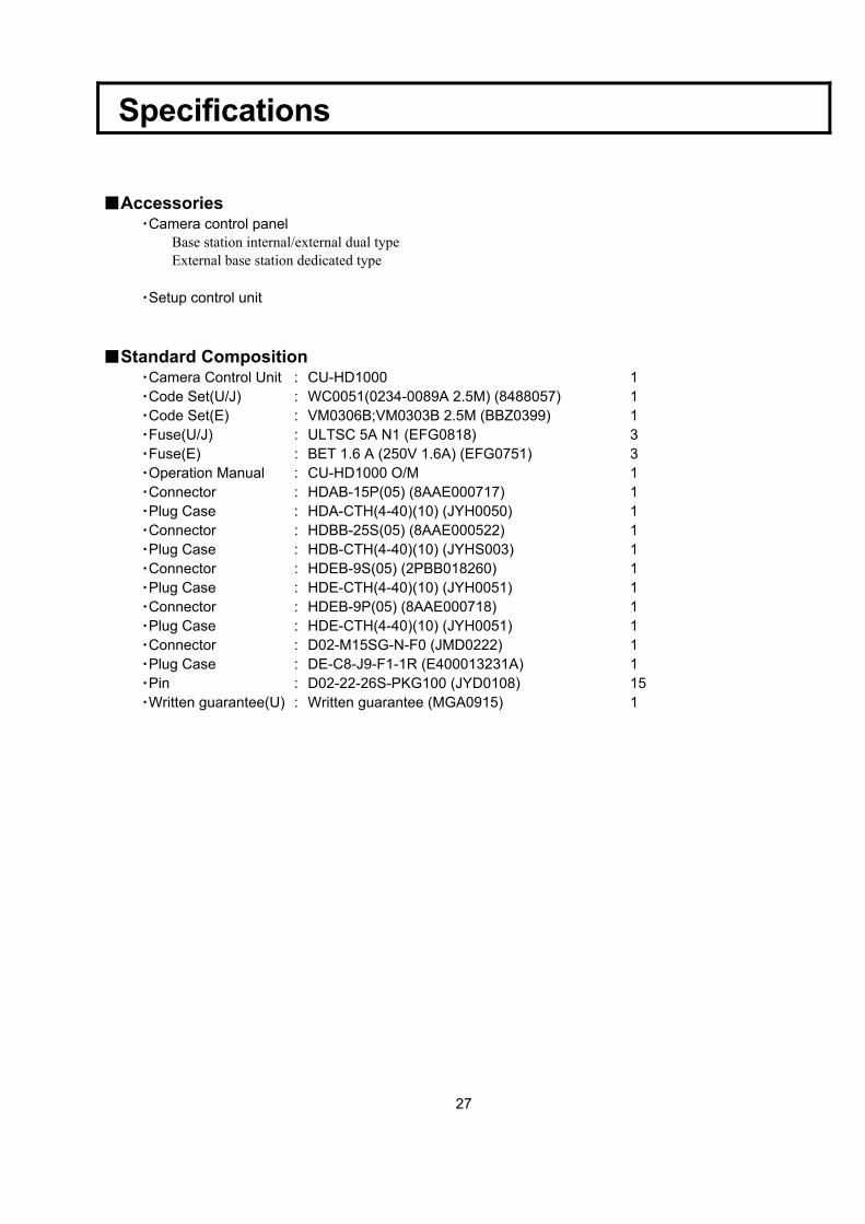
■Accessories ・Camera control panel
Base station internal/external dual type External base station dedicated type
・Setup control unit
■Standard Composition ・Camera Control Unit : CU-HD1000 1 ・Code Set(U/J) : WC0051(0234-0089A 2.5M) (8488057) 1 ・Code Set(E) : VM0306B;VM0303B 2.5M (BBZ0399) 1 ・Fuse(U/J) : ULTSC 5A N1 (EFG0818) 3 ・Fuse(E) : BET 1.6 A (250V 1.6A) (EFG0751) 3 ・Operation Manual : CU-HD1000 O/M 1 ・Connector : HDAB-15P(05) (8AAE000717) 1 ・Plug Case : HDA-CTH(4-40)(10) (JYH0050) 1 ・Connector : HDBB-25S(05) (8AAE000522) 1 ・Plug Case : HDB-CTH(4-40)(10) (JYHS003) 1 ・Connector : HDEB-9S(05) (2PBB018260) 1 ・Plug Case : HDE-CTH(4-40)(10) (JYH0051) 1 ・Connector : HDEB-9P(05) (8AAE000718) 1 ・Plug Case : HDE-CTH(4-40)(10) (JYH0051) 1 ・Connector : D02-M15SG-N-F0 (JMD0222) 1 ・Plug Case : DE-C8-J9-F1-1R (E400013231A) 1 ・Pin : D02-22-26S-PKG100 (JYD0108) 15 ・Written guarantee(U) : Written guarantee (MGA0915) 1