CTS25/Concept 25 - BlindShadeMotors 25 Fabrication Instructions 1” Horizontal Products DESCRIPTION...
8
CTS25/Concept 25 Fabrication Instructions 1” Horizontal Products DESCRIPTION COMPONENTS SYSTEM CONFIGURATIONS LW & LV Motor LW or LV Concept 25 (B83/B64) AMS (#6050000) Headrail adapters (#6050600) CTS25 Kit (#6180404) 5mm Hexagonal Shaft (#6050406) 5mm Hexagonal Shaft Adapters (#6050003) Stop Collar Ring for 5mm Shaft (#6050400) The new patented Cord Take-Up System (CTS) for window coverings enables lift and tilt functions and prevents cord slippage, tangling and overlap. By using the Cord Take-Up System versus a tape lift system, you achieve increased product reliability, and smoother more uniform operation. What's more, fabricating window coverings with (CTS) is an easier process. Motorization with Concept 25 is quite simple... Comprised of only 7 primary components, this 24V DC LOW VOLTAGE motorization system can lift and tilt the most 2” horizontal blind products. LW 25-B83 24 VDC 0.8 N/m 30 rpm IP 40 600 mA made in France A M S 25 Head Rail Adaptors AMS Stop Collar Ring Concept 25 Motor CTS 25 Hexagonal Shaft Hexagonal Shaft Adapters cone cover ring cradle
Transcript of CTS25/Concept 25 - BlindShadeMotors 25 Fabrication Instructions 1” Horizontal Products DESCRIPTION...

CTS25/Concept 25Fabrication Instructions
1” Horizontal Products
DESCRIPTION
COMPONENTS
SYSTEM CONFIGURATIONS LW & LV
Motor LW or LV Concept 25 (B83/B64)
AMS (#6050000)
Headrail adapters (#6050600)
CTS25 Kit (#6180404)
5mm Hexagonal Shaft (#6050406)
5mm Hexagonal Shaft Adapters (#6050003)
Stop Collar Ring for 5mm Shaft (#6050400)
The new patented Cord Take-Up System (CTS) for windowcoverings enables lift and tilt functions and prevents cordslippage, tangling and overlap. By using the Cord Take-Up Systemversus a tape lift system, you achieve increased product reliability,and smoother more uniform operation. What's more, fabricatingwindow coverings with (CTS) is an easier process.
Motorization with Concept 25 is quite simple...Comprised of only 7 primary components, this24V DC LOW VOLTAGE motorization system canlift and tilt the most 2” horizontal blind products.
LW 25 -B8324 VDC 0.8 N/m 30 rpmIP 40 600 mA
made in FranceJAPAN & US Patent Pending
AMS
25
Head Rail Adaptors
AMSStop Collar
RingConcept 25 Motor CTS 25 Hexagonal
Shaft
Hexagonal Shaft
Adapters
cone cover ringcradle

TECHNICAL SPECIFICATIONS
1 INCH HORIZONTAL PRODUCTS
2
LV 25-B44
LV 25-B64
LW 25-B44
LW 25-B83
Single
Single
Double
Double
11.5 Ft.
11.5 Ft.
11.5 Ft.
11.5 Ft.
22 Sq. Ft.
44 Sq. Ft.
22 Sq. Ft.
54 Sq. Ft.
40
35
40
30
Output ShaftMotor Type
Specifications based on motors used with (CTS). They are approximate and may vary
depending on product application, fabric etc.
Maximum area for
25mm Aluminum Blinds
Sq. ft.
Speed
(RPM)
Maximum height
with 1.4 mm cord
MINIMUM WIDTH OF BLIND
LV Motor
LW Motor
21 1/8”
24 3/4” 24 1/4” 27 3/4”
6 Inch Route Hole4 1/4 Inch Route Hole1 1/2 Inch Route Hole 6 3/4 Inch Route HoleMotor Type
ASSEMBLY INSTRUCTIONS
A. Headrail Preparation
1. Cut or specify headrail width that is suitable for shade application.
2. Punch standard cord route holes into headrail. See above chart for route hole positions and shade width minimums.For retrofit applications, use existing route holes
6 Min” For LW Motors
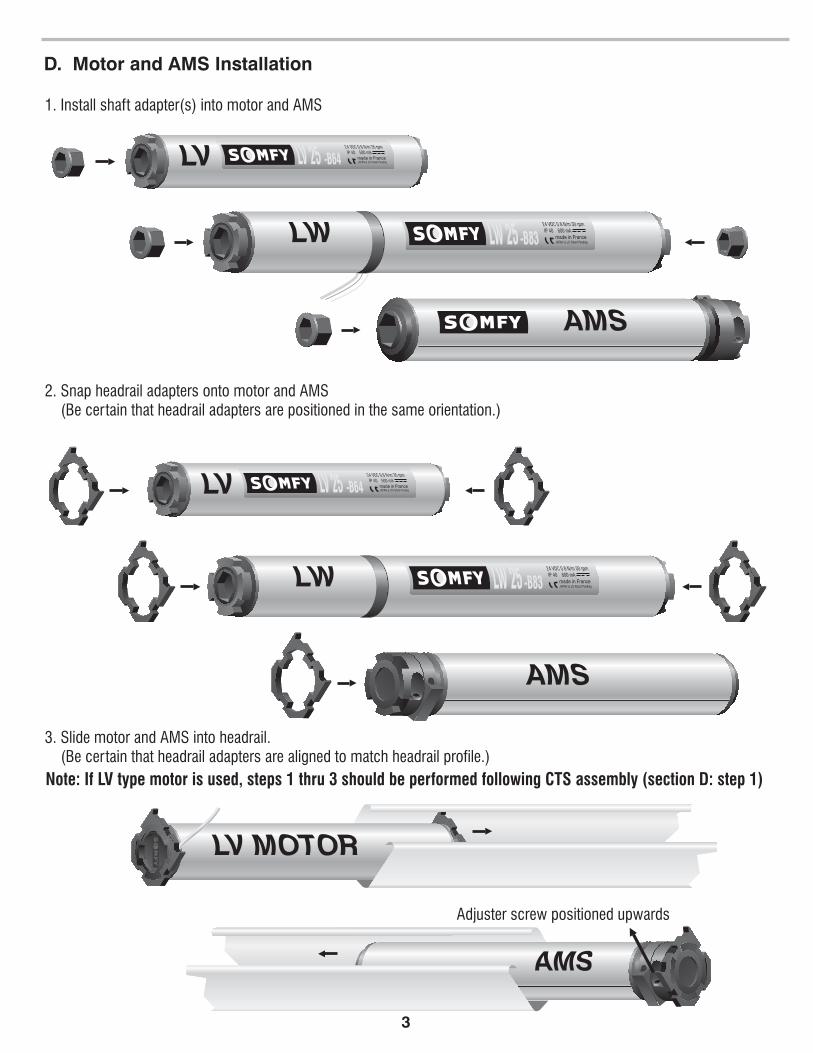
1. Install shaft adapter(s) into motor and AMS
2. Snap headrail adapters onto motor and AMS(Be certain that headrail adapters are positioned in the same orientation.)
3. Slide motor and AMS into headrail.(Be certain that headrail adapters are aligned to match headrail profile.)
Adjuster screw positioned upwards
Note: If LV type motor is used, steps 1 thru 3 should be performed following CTS assembly (section D: step 1)
D. Motor and AMS Installation
3

1. Cut the ladder braids to measure 3 1/2”from top slat ladder
2. Fasten ladder grip to create a loop(see illustration).
NOTE: The ladder grip bepositioned under the top slat ladder
must
Ladder
Grip
Top Slat LadderTop Slat Ladder3 ”1/2
C. Ladder Braid Assembly
D. CTS Assembly
1. Insert cradle bearings into headrail and align at pre-punched route holes. Ensure that cradles are seated correctlyinto route holes of headrail.
Route Hole Route Hole Cradle BearingCradle Bearing
AMSLW 25 Motor
Front view of headrail
4
LW 25 -B8324 VDC 0.8 N/m 30 rpmIP 40 600 mA
made in FranceJAPAN & US Patent Pending
AMS
25
(step 1) (step 2)
2. Feed the take-up cords through the hole of the cradle bearings, then feed ladder braids through the cradle bearing.(Note: 1.4mm round braided polyester type cord is recommended.)
3. Slide each CTS cone into headrail,making sure the ladder braid loopsrest in the groove of each cone.
4. Insert tip of each cone intocradle bearings.
Take-up
Cord Ladder
Braid
Cradle Bearing
Ladder Braid
in Groove
CTS Cone
Side View Pull Cord Slightly
Take-up
Cord
CTS ConeLadder Braid
5. Lightly pull on each take-up cord to be certainthey are not restricted.
Take-up Cord
Bottom of
Cradle Bearing
Blind Ladder Braid

2. Temporarily hang the blind and extendto a "lowered position." (be certaintake-up cords remain accessible.)
3. With blind hanging in a "lowered position”carefully mark each take-up cordwith regard to each aligned “V-groove”and tie knot. (see detail).
4. Insert take-up cord knot into grooveof cone and fasten cone ring as shown.
5. Attach cone ring and “snap” conecover onto cradle bearing
1. Align the grooves at the end of each cone.
Top View of Headrail
Grooves Aligned
Extend Blind
Take-up Cords
E. Securing Take-up Cords
Note: Steps 2 and 3 may be eliminated if take-up cords are initially cut/measured to same lengths.Simply tie knots in each cord, and proceed to step 4. Final cord adjustment (for shade levelness)may be completed at bottom rail of blind.
5
LW 25 -B8324 VDC 0.8 N/m 30 rpmIP 40 600 mA
made in FranceJAPAN & US Patent Pending
AMS
25
Cone Ring
Cone Cover
Cradle
Bearing
Snap
Marked Take-up
Cord
Cone Groove
Knot Tied
at Mark
Cut
Excess

6
LV 25 -B6424 VDC 0.6 N/m 35 rpmIP 40 500 mA
made in FranceJAPAN & US Patent Pending
LV 25 Motor
Configuration C
LW 25 -B8324 VDC 0.8 N/m 30 rpmIP 40 600 mA
made in FranceJAPAN & US Patent Pending
AMS25
AMS 25LW 25 Motor CTS 25CTS 25
Measuring
Points
Measuring
Points
Configuration B
LW 25 -B8324 VDC 0.8 N/m 30 rpmIP 40 600 mA
made in FranceJAPAN & US Patent Pending
AMS25
AMS 25LW 25 Motor
Measuring
PointsMeasuring
Points
CTS 25CTS 25
1. Measure approximately and cut the appropriate length of hexagonal shaft.(see examples below for approximate measuring points).
2. Deburr shaft ends.
F. Hex Shaft Assembly
AMS 25 CTS 25
Measuring
Points
Configuration A
CTS 25
A MS
25

3. LW motors will require two shafts:Insert shaft #1Insert shaft #2(If LV motor is used, insert shaft #1 only).
through CTS, AMS, Stop Collar Ring, and into motor.through CTS, Stop Collar Ring, and into motor.
4. Slide AMS against nearest CTS. Position Stop Collar Ring #1 against front of AMS and secure.This will prevent the AMS from sliding and eliminate loosening of shaft from motor unit.
5. Slide stop collar ring #2 to front of CTS and secure.
F. Hex Shaft Assembly (continued)
LW 25 -B8324 VDC 0.8 N/m 30 rpmIP 40 600 mA
made in FranceJAPAN & US Patent Pending
AMS
25
AMSStop Collar
RingConcept 25 Motor CTS 25 Hexagonal
Shaft #1
Hexagonal
Shaft #2
AMS
25
Stop Collar Ring #1 1/16" Gap Between AMS & CTS
LW 25 -B8324 VDC 0.8 N/m 30 rpmIP 40 600 mA
made in FranceJAPAN & US Patent Pending
AMS
25
Hex. Shaft
AMSStop Collar
Ring #2
Stop Collar
Ring #1Concept 25
MotorCTS 25
NOTE: Proper alignment of cones MUST be maintained to assure even blind operation. Be
certain that “V-Grooves” are visible through cone cover when inserting hexagonal shaft into
each CTS. (see figure below)
“V-Groove”
Cone Cover
TOP VIEW OF CTS
7

1. Apply power to motor and operate in each direction.
2. Adjust take-up cords at bottom bar for levelness (if necessary)
3. Regulate the overall length of blind travel by adjusting the AMS.(see adjusting the AMS below)
1. Apply power to motor and operate in each direction.
2. To shorten the overall drop length of blind, operate blind to desired stop position, turn the AMS adjuster screwin direction #2 until screw will no longer turn freely.
3. To increase the overall drop length of blind, simply turn the AMS adjuster screw in direction #1 until desiredlength is reached.
(Note: 12.5 revolutions of the adjuster screw equals 1 revolution of hexagonal shaft)
(Note: Overall blind length is restricted to the length of take-up cords...)
G. Final Adjustments
H. Adjusting the AMS
1
2
8
SOMFY MEXICO, S.A. De C.V.
Calle 3 No. 47, Loc. E-5
Fracc Ind. Alce Blanco
Nau., Edo. de Mex
C.P. 53370
SOMFY SYSTEMS, INC.
1-800-437-6639
47 Commerce Drive
Cranbury, NJ 08512
SOMFY CANADA
6315 Shawson Drive, Unit #1
Mississauga, Ontario L5T1J2
SOMFY SYSTEMS, INC. reserves the right
to update, change or improve this product
without further notice. c SOMFY SYSTEMS, INC. 9/01


![B64-4164-00 00 M English - KENWOODmanual.kenwood.com/files/B64-4164-00_English.pdfDisc ejection [0] ⁄ • You can eject the disc for 10 minutes after switching off the engine. USB](https://static.fdocuments.us/doc/165x107/5f01dfec7e708231d40175a0/b64-4164-00-00-m-english-disc-ejection-0-a-a-you-can-eject-the-disc-for.jpg)