CTRL: A Self-Organizing Femtocell Management Architecture ... · CTRL: A Self-Organizing Femtocell...
12
CTRL: A Self-Organizing Femtocell Management Architecture for Co-Channel Deployment Ji-Hoon Yun and Kang G. Shin Real-Time Computing Laboratory, EECS Department The University of Michigan, Ann Arbor, MI 48109-2121, U.S.A. {jihoony, kgshin}@eecs.umich.edu ABSTRACT Femtocell technology has been drawing considerable attention as a cost-effective means of improving cellular coverage and capacity. However, under co-channel deployment, femtocells may incur high uplink interference to existing macrocells, and vice versa. To alle- viate this interference, we propose a distributed and self-organizing femtocell management architecture, called CTRL (Complementary TRi-control Loops), that consists of three control loops. First, for protection of macrocell users’ uplink communications, CTRL con- trols the maximum TX power of femtocell users based on the fed- back macrocell’s load margin so as to keep, on average, the macro- cell load below a certain threshold. Second, CTRL determines the target SINRs of femtocell users, conditioned on the maximum TX power, to reach a Nash equilibrium based on their utility functions, thus achieving efficient coordination of uplink usage among fem- tocells. Third, for protection of femtocell users’ uplink communi- cations, the instantaneous TX power of each femtocell user is con- trolled to achieve the target SINR against bursty interference from nearby macrocell or femtocell users. Our in-depth evaluation has shown CTRL to successfully pre- serve the macrocell users’ service quality from femtocells’ inter- ference and converge to an optimal point under highly dynamic user TX conditions. CTRL is also shown to limit the effects of the estimation errors of channel gains and feedback delay. Categories and Subject Descriptors C.2.1 [Computer-Communication Networks]: Network Archi- tecture and Design—Wireless communication General Terms Algorithms, Design, Performance, Theory Keywords Femtocell, home base station, co-channel deployment, interference mitigation, self-organizing networks Permission to make digital or hard copies of all or part of this work for personal or classroom use is granted without fee provided that copies are not made or distributed for profit or commercial advantage and that copies bear this notice and the full citation on the first page. To copy otherwise, to republish, to post on servers or to redistribute to lists, requires prior specific permission and/or a fee. MobiCom’10, September 20–24, 2010, Chicago, Illinois, USA. Copyright 2010 ACM 978-1-4503-0181-7/10/09 ...$10.00. 1. INTRODUCTION Femtocell technology has emerged as a cost-effective means to enhance indoor network coverage and capacity for growing de- mands for cellular (voice calls and data) services within a home or an enterprise environment [1]. A femtocell is a small indoor area covered by a low-power base station (BS), referred to as a femto BS in this paper. Unlike macro BSs, femto BSs are installed on the subscriber’s premise and typically connected to an operator’s core network via public Internet connections, such as DSL and cable modems. Femtocells benefit both subscribers and operators; better voice coverage and higher indoor data throughput for subscribers, and macrocell offloading and indoor coverage improvement at low capital and operational costs for operators. A main challenge associated with the femtocell technology is how to protect, under co-channel deployment, macrocell user ser- vices against interference from femtocells while exploiting as high spatial reuse of channel resources as possible within femtocells. Due to the high cost of a licensed spectrum, operators may allo- cate femtocells the same carrier frequency as macrocells, called co- channel deployment. Under co-channel deployment, transmissions within femtocells may cause interference to user services within macrocells, and vice versa [2]. Such a phenomenon has been re- ported as a serious problem in uplink (UL) communications [3–6]. The resultant performance degradation makes the femtocell tech- nology’s market penetration difficult since the deteriorated service to existing users will increase the churn rate. It is, therefore, im- portant to solve this interference problem by managing femtocells efficiently and effectively. The distinct features of femtocell technology impose the follow- ing requirements on femtocell management. First, considering the fact that femtocells are to be deployed on an already-existing and working cellular infrastructure, the femtocell management should minimize the change of a performance-critical part of macro BSs, especially radio resource management (RRM). The RRM within existing macrocells has been optimized and validated in the field under a wide range of cell conditions, e.g., traffic patterns, quality- of-service (QoS), and user mobility. Changing the macrocell RRM may require tedious and time-consuming optimizations. Second, salient features of femtocells, such as user installation and unplanned deployment, require femtocell management to be distributed and self-organizing, and hence, convergence becomes a critical factor. These features, along with its restricted access, make the femtocell management very different from the classical hierarchical cell coor- dination problem. Besides, supporting legacy user devices without using any special hardware is another important requirement. There have been a few proposals to resolve the femtocell interfer- ence problem in UL communications, but they have, unfortunately, several limitations. Vikram et al. [4] proposed a coordinated UL
Transcript of CTRL: A Self-Organizing Femtocell Management Architecture ... · CTRL: A Self-Organizing Femtocell...

CTRL: A Self-Organizing Femtocell ManagementArchitecture for Co-Channel Deployment
Ji-Hoon Yun and Kang G. Shin
Real-Time Computing Laboratory, EECS DepartmentThe University of Michigan, Ann Arbor, MI 48109-2121, U.S.A.
{jihoony, kgshin}@eecs.umich.edu
ABSTRACTFemtocell technology has been drawing considerable attention as acost-effective means of improving cellular coverage and capacity.However, under co-channel deployment, femtocells may incur highuplink interference to existing macrocells, and vice versa. To alle-viate this interference, we propose a distributed and self-organizingfemtocell management architecture, called CTRL (ComplementaryTRi-control Loops), that consists of three control loops. First, forprotection of macrocell users’ uplink communications, CTRL con-trols the maximum TX power of femtocell users based on the fed-back macrocell’s load margin so as to keep, on average, the macro-cell load below a certain threshold. Second, CTRL determines thetarget SINRs of femtocell users, conditioned on the maximumTXpower, to reach a Nash equilibrium based on their utility functions,thus achieving efficient coordination of uplink usage amongfem-tocells. Third, for protection of femtocell users’ uplink communi-cations, the instantaneous TX power of each femtocell user is con-trolled to achieve the target SINR against bursty interference fromnearby macrocell or femtocell users.
Our in-depth evaluation has shown CTRL to successfully pre-serve the macrocell users’ service quality from femtocells’ inter-ference and converge to an optimal point under highly dynamicuser TX conditions. CTRL is also shown to limit the effects oftheestimation errors of channel gains and feedback delay.
Categories and Subject DescriptorsC.2.1 [Computer-Communication Networks]: Network Archi-tecture and Design—Wireless communication
General TermsAlgorithms, Design, Performance, Theory
KeywordsFemtocell, home base station, co-channel deployment, interferencemitigation, self-organizing networks
Permission to make digital or hard copies of all or part of this work forpersonal or classroom use is granted without fee provided that copies arenot made or distributed for profit or commercial advantage and that copiesbear this notice and the full citation on the first page. To copy otherwise, torepublish, to post on servers or to redistribute to lists, requires prior specificpermission and/or a fee.MobiCom’10,September 20–24, 2010, Chicago, Illinois, USA.Copyright 2010 ACM 978-1-4503-0181-7/10/09 ...$10.00.
1. INTRODUCTIONFemtocell technology has emerged as a cost-effective meansto
enhance indoor network coverage and capacity for growing de-mands for cellular (voice calls and data) services within a homeor an enterprise environment [1]. Afemtocellis a small indoor areacovered by a low-power base station (BS), referred to as afemtoBSin this paper. Unlike macro BSs, femto BSs are installed on thesubscriber’s premise and typically connected to an operator’s corenetwork via public Internet connections, such as DSL and cablemodems. Femtocells benefit both subscribers and operators;bettervoice coverage and higher indoor data throughput for subscribers,and macrocell offloading and indoor coverage improvement atlowcapital and operational costs for operators.
A main challenge associated with the femtocell technology ishow to protect, under co-channel deployment, macrocell user ser-vices against interference from femtocells while exploiting as highspatial reuse of channel resources as possible within femtocells.Due to the high cost of a licensed spectrum, operators may allo-cate femtocells the same carrier frequency as macrocells, calledco-channel deployment. Under co-channel deployment, transmissionswithin femtocells may cause interference to user services withinmacrocells, and vice versa [2]. Such a phenomenon has been re-ported as a serious problem in uplink (UL) communications [3–6].The resultant performance degradation makes the femtocelltech-nology’s market penetration difficult since the deteriorated serviceto existing users will increase the churn rate. It is, therefore, im-portant to solve this interference problem by managing femtocellsefficiently and effectively.
The distinct features of femtocell technology impose the follow-ing requirements on femtocell management. First, considering thefact that femtocells are to be deployed on an already-existing andworking cellular infrastructure, the femtocell management shouldminimize the change of a performance-critical part of macroBSs,especially radio resource management (RRM). The RRM withinexisting macrocells has been optimized and validated in thefieldunder a wide range of cell conditions, e.g., traffic patterns, quality-of-service (QoS), and user mobility. Changing the macrocell RRMmay require tedious and time-consuming optimizations. Second,salient features of femtocells, such as user installation and unplanneddeployment, require femtocell management to bedistributedandself-organizing, and hence, convergence becomes a critical factor.These features, along with its restricted access, make the femtocellmanagement very different from the classical hierarchicalcell coor-dination problem. Besides, supporting legacy user deviceswithoutusing any special hardware is another important requirement.
There have been a few proposals to resolve the femtocell interfer-ence problem in UL communications, but they have, unfortunately,several limitations. Vikramet al. [4] proposed a coordinated UL

power-control architecture for both macro- and femto-cells, whichrequires macrocells to use their proposed power-control algorithm.Joet al. [6] proposed a simple up/down UL power control for fem-tocells. Their scheme adjusts the transmit (TX) power of femto-cell users in proportion to the fed-back interference levelof macro-cells and does not require any change of the macrocell RRM. How-ever, they focused only on the protection of a macrocell’s ULcom-munication and their scheme does not guarantee convergenceei-ther. Moreover, both proposals did not consider the feedback de-lay. Yavuzet al. [3] proposed an attenuator adjustment scheme re-stricted to femtocell UL protection against nearby macrocell users.Proposals for protection of downlink (DL) communications [5, 7]are neither effective nor optimal for UL communications as theyoperate based only on a femtocell’s local condition, ignoring themacrocell’s UL state. Sundaresan and Rangarajan’s recent study[8] focused on OFDMA-based femtocell systems, mainly dealingwith orthogonal assignment of time-frequency resources betweenmacro- and femto-cells:strictly orthogonalin the isolated modelandorthogonalbetween neighboring macrocell and femtocell usersonly in the coupled model for higher total utility. However,bothof these models require modification of the macrocell RRM duetotheir tightly-coupled coordination of macro- an femto-cells withoutconsidering the other requirements.
To overcome the above limitations of existing schemes in single-carrier cellular systems, we propose a distributed and self-organizingfemtocell management architecture for UL communications,calledComplementaryTRi-control Loops(CTRL). The key idea behindCTRL is the use of multiple control loops optimally designedwithdifferent objectives while complementing each other toward a com-mon goal. These control loops and their complementary interac-tions are summarized as follows.
• Maximum transmit power control(MTXPC) loop protectsthe macrocell’s UL communication against the interferencefrom femtocells. This is achieved by controlling the maxi-mum TX power of femtocell users based on the macrocellUL load margin fed back with delay such that the macrocellload does not exceed, on average, a given threshold.
• Target signal-to-interference and noise ratio control(TSINRC)loop enables utility-optimal resource coordination amongfem-tocells without signaling between them while being condi-tioned on the maximum TX power constraint obtained by theMTXPC loop. The control algorithm is designed to achievea Nash Equilibrium for general utility functions.
• Instantaneous transmit power control(ITXPC) loop protectsthe femtocell’s UL communication against bursty interfer-ence from nearby macrocell or femtocell users. It controlsthe TX power of a femtocell user such that the target SINRdetermined by the TSINRC loop is achieved on a small time-scale (e.g., frame).
CTRL meets all the requirements mentioned earlier. That is,CTRL does not require modification of the RRM of macro BSs,thus enabling smooth migration of co-channel femtocells into ex-isting cellular networks. The control algorithms of CTRL alsoachieve convergence under the provided conditions againsttime-varying and unpredictable environmental changes, such as inter-ference, threshold value, etc. Besides, CTRL is compatiblewithlegacy user devices since it does not impose any non-standard op-eration on them. CTRL is software-based, does not increase thehardware cost, and can be improved further with an extra receivermodule enabling the over-the-air feedback (as detailed in Section3).
MU1
Macro BS
Femtocellmanager
Femtocellgateway
DSL/Cable modem
FBS2
FBS1
FU1FU2
SignalInterference
MacrocellOAM server
Operator’s core network
Figure 1: Uplink interference scenarios under co-channel fem-tocell deployment
Our evaluation results show that CTRL successfully protects amacrocell’s uplink service regardless of the number of femtocells inthe macrocell. In an example scenario with 50 macrocell users and100 femtocell users per macrocell, 96% of macrocell users meetthe specified service quality while only 8% of them meet it with-out CTRL. Moreover, CTRL converges to an optimal point underawide range of user traffic dynamics and maintains stability againstup to 100% errors in estimating the channel gains and feedbackdelay.
The rest of this paper is organized as follows. Sections 2 and3 describe the motivation of this work and the system model, re-spectively. Section 4 presents the CTRL architecture, and Section5 describes the control algorithms. Section 6 evaluates theCTRLarchitecture using simulation, and Section 7 concludes thepaper.
2. MOTIVATIONWe first advocate the necessity of femtocell management for UL
communications. Then, we discuss the requirements of femtocellmanagement and identify the limitations in applying existing tech-niques to femtocell networks.
2.1 Why Femtocell Management for UL Com-munications?
The initial motivation behind the introduction of femtocells tocellular networks was extension of indoor coverage for voice calls.However, the femtocell technology provides an important addi-tional advantage, especially for data services: overall data capacityimprovement due to spatial channel reuse and macrocell offload-ing. Subscribers also have incentives to use femtocells even withina macrocell coverage for better indoor data throughput, less devicepower consumption (longer battery life) and possibly an unlimiteddata plan. Under the expected co-channel femtocell deployment,however, UL transmissions of femtocell users (users being servedby femtocells) may cause interference to the ongoing UL transmis-sions of users being served by macrocells, and vice versa. Severalresearchers [3–6] reported such a phenomenon and the resultantperformance degradation of both macrocell and femtocell users inUL communications as a serious problem.
We illustrate possible UL interference scenarios between macro-and femto-cells in Fig. 1 as follows. Due to their unplanned de-ployment, some femtocells (FBS1) could reside close to a macroBS and their users (FU1) will incur high UL interference to themacro BS. The opposite may also happen when a macrocell user(s)(MU1) resides in the vicinity of a femto BS (FBS1). To make mat-
-80 -60 -40 -200.0
0.5
1.0 F/M = 0 F/M = 30 F/M = 50 F/M = 100
SINR of macrocell users (dB) 0 20 40 60 80 100
-110
-100
-90
-80 Femto BS A Femto BS B Femto BS C
dBm
Slot index
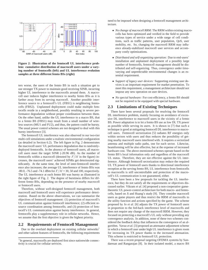
Figure 2: Illustration of the femtocell UL interference pro b-lem: cumulative distribution of macrocell users under a vary-ing number of femtocells (left) and UL interference evolutionsamples at three different femto BSs (right)
ters worse, the users of the femto BS in such a situation get touse stronger TX power to maintain good receiving SINR, incurringhigher UL interference to the macrocells around them. A macro-cell user induces higher interference to nearby femto BSs asit isfarther away from its serving macrocell. Another possible inter-ference source to a femtocell’s UL (FBS1) is neighboring femto-cells (FBS2). Unplanned deployment could make multiple fem-tocells reside in a neighborhood, possibly resulting in severe per-formance degradation without proper coordination betweenthem.On the other hand, unlike the UL interference to a macro BS, thatto a femto BS (FBS1) may result from a small number of wire-less sources (MU1 and FU2), and thus, the pattern could be bursty.The usual power control schemes are not designed to deal withthisbursty interference [3].
The femtocell UL interference was also observed in our two-tiermulti-cell simulations under a realistic environmental configuration(as detailed in Section 6.2). The left figure in Fig. 2 demonstratesthe macrocell users’ UL performance degradation due to randomly-deployed femtocells. In the absence of femtocell users, allmacro-cell users meet the target SINR (-20.96 dB). As the number offemtocells within a macrocell (denoted byF/M in the figure) in-creases, the macrocell users’ achieved SINRs get deteriorated sig-nificantly. At the same time, the level of inter-femtocell interfer-ence also increases; the average UL interference of femto BSs was-80.0, -76.5 and -74.1 dBm forF/M = 30, 50 and 100, respectively.The UL interference at each femto BS was bursty as illustrated inthe right figure of Fig. 2. The degree of burstiness differs for dif-ferent femto BSs, depending on the presence of nearby macrocellor femtocell users.
Therefore, without well-designed femtocell management, bothmacrocell and femtocell users will experience performancedeteri-oration. Based on the above observations, we can summarize theobjectives of femtocell management: (1) protection of macrocell’sUL communication against femtocell interference; (2) efficient re-source coordination among femtocells; and (3) protection of fem-tocell’s UL communication against bursty interference. Ingeneral,femtocells play a supplementary role in cellular networks.Hence,we assume that the first objective is given the highest priority.
2.2 Requirements of Femtocell ManagementDue to the overlaid deployment on existing cellular networks1
and other salient features of femtocells, the following requirements
1In general, macrocells are deployed first since nationwide connec-tivity is crucial for cellular services.
need to be imposed when designing a femtocell management archi-tecture.
• No change of macrocell RRM:The RRM within existing macro-cells has been optimized and verified in the field to providevarious types of service under a wide range of cell condi-tions, such as traffic patterns, user population, QoS, usermobility, etc. So, changing the macrocell RRM may influ-ence already-stabilized macrocell user services and accom-pany costly optimizations.
• Distributed and self-organizing operation:Due to end-users’installation and unplanned deployment of a possibly largenumber of femtocells, femtocell management should be dis-tributed and self-organizing. Thus, convergence under time-varying and unpredictable environmental changes is an es-sential requirement.
• Support of legacy user devices:Supporting existing user de-vices is an important requirement for market penetration. Tomeet this requirement, a management architecture should notimpose any new operation on user devices.
• No special hardware:For cost-efficiency, a femto BS shouldnot be required to be equipped with special hardware.
2.3 Limitations of Existing TechniquesThere have been several proposals for resolving the femtocell
DL interference problem, mainly focusing on avoidance of exces-sive DL interference to macrocell users in the vicinity of a femtoBS. Power adaptation is to let a femto BS use as low DL TX poweras possible while serving its users. It is shown in [7] that such atechnique is good at mitigating femtocell DL interference to macro-cell users. Femtocell sectorization [5] radiates RF energies onlywithin sectors with users and thus reduces the possibility of get-ting nearby macrocell users interfered with. It requires a sectorizedantenna and multiple radio paths, one for each sector. Likewise,beamforming will be also effective, but at the expense of increasedhardware cost. The above-mentioned schemes operate based on thefemto BS’s local information only and regardless of the macrocellUL status. Therefore, they are not effective against the UL inter-ference. Although femtocell sectorization may reduce the requiredUL TX power of femtocell users thanks to directional interferencereception at the serving femto BS, UL interference from femtocellsto macrocells is still uncontrollable and protection of themacro-cell’s UL communication is not guaranteed, either.
There have been a few proposals for tackling the UL interfer-ence, but they do not satisfy all the requirements or objectives dis-cussed earlier. Vikramet al. [4] proposed a non-cooperative game-theoretic UL power-control architecture for both macro- and femto-cells, based on Ji and Huang’s study [9]. They consider macrocellusers as game players and thus restrict the RRM of macrocellstothe utility function and actions specified by the game. The schemeproposed by Joet al. [6] adjusts the TX power of femtocell usersin proportion to the fed-back interference level of macrocells anddoes not require any change of the macrocell RRM. However, theyfocused on protecting a macrocell’s UL only without providing anyconvergence analysis. In addition, none of these two schemes con-sidered the feedback delay that influences the convergence of an al-gorithm. Yavuzet al.[3] proposed an attenuator adjustment schemein which a femtocell user under high UL interference is givenroomfor increasing its TX power thanks to the increased attenuation.This scheme is restricted to femtocell UL protection.
There was a recent proposal targeting OFDMA systems by Sun-daresan and Rangarajan [8]. In their isolated model, a macroBS

and femto BSs are allocated orthogonal time-frequency resourceswhile the coupled model imposes this constraint on neighboringmacrocell and femtocell users to achieve higher total utility. Torealize these two models, each femto BS requires time synchro-nization with a macro BS and an extra receiving module with self-interference cancellation capability for overhearing macrocell sig-nals (neither of them is required in CTRL; difficulties and somesolutions of the over-the-air feedback will be discussed inSection3.2). Moreover, both models require modification of macro BSs’RRM for dynamic adjustment of resource split.
3. SYSTEM MODELThis section describes the network architecture under considera-
tion and two implementation alternatives for macrocell-load feed-back.
3.1 Network ArchitectureWe consider a single-carrier cellular system (e.g., CDMA) and
a typical two-tier femtocell network architecture depicted in Fig. 1where femtocells are overlaid on macrocells. The set of macrocellsM = {1, . . . , M} and the set of femtocellsF = {1, . . . , F} usean identical carrier frequency. Cellm operates under BSm. Theset of macrocell users and that of femtocell users are representedbyMu = {1, . . . , Mu} andFu = {1, . . . , Fu}, respectively. Thechannel gain from useri to BS j is denoted byhi,j . We assumethat useri transmits data with the activity factorai (0 ≤ ai ≤ 1).
As in general cellular networks, every BS has a logical con-nection to an Operation, Administration and Management (OAM)server that BSs receive initial configuration settings fromand occa-sionally report their status to. We refer to the OAM server dedicatedto femtocells as thefemtocell manager.
3.2 Macrocell-Load FeedbackFor protection of macrocell users’ UL communications, femto
BSs need to know the current status of macrocells—as was as-sumed in [4, 6]—which can be enabled by the feedback from macroBSs, referred to asmacrocell feedback. We assume that a macro BSfeeds back itscell load margindefined as the difference betweenthe current cell load and a given load threshold; the cell load mar-gin is positive when the current load is lower than the threshold,else it is negative. Two implementation alternatives for macrocellfeedback, differing in delay and cost, are described next.
3.2.1 Feedback over wired networksFirst, we consider the approach that femto BSs receive macro-
cell feedback through the operator’s wired network. To realize this,each macro BS periodically reports its cell load margin to the OAMserver. Then, the macrocell OAM server forwards it to the femto-cell manager. Finally, the femtocell manager sends it to thefemtoBSs that have subscribed to the feedback of the macro BS. Notethatsignaling interfaces for OAM are generally vendor-specific. To re-ceive the feedback from proper macro BSs, femto BSs need to exe-cute a subscription procedure; when powered on, a femto BS scansneighbor macrocells and reports the list of macrocell feedback sub-scriptions to the femtocell manager.
‘Feedback over wired networks’ does not require additionalhard-ware of femto BSs, but has a larger delay than the other approach.
3.2.2 Feedback over the airIn the second approach, femto BSs receive macrocell feedback
directly from macro BSs over the air. Specifically, macro BSsbroadcast their load margin information which is then overheardby femto BSs. This approach requires two issues to be resolved:
MTXPC
ITXPC TSINRC
MaximumTX power
Target SINR
InstantaneousTX power
(interference to macrocell)
Figure 3: Complementary interactions between control loops
Cellload
Threshold of macrocell load
Macrocell loadCell load margin
PowerMax. TX power of femtocell user
Interference
Tx power for target SINR
Macrocell uplink
Femtocell uplink
MTXPC loop
Figure 4: Overview of the CTRL concept
implementation feasibility and standard violation. We discuss eachof them next.
In the case of frequency-division duplex (FDD), femto BSs needto overhear macrocell signals at a frequency other than their origi-nal RX frequency, i.e., they require an extra receiver module. Thetime-division duplex (TDD) also requires this to enable full du-plexing (receiving macrocell signals during an active transmission).On the other hand, if macro BSs feed back information using thesame frequency that femto BSs use to transmit data, femto BSsmay not be able to demodulate macrocell signals due to signifi-cant self-interference. This problem can be addressed by (1) themacrocell’s feedback at a frequency different from the femtocell’sTX frequency or (2) interference cancellation as in wireless relays[10]. The first solution is applicable only when macro BSs usemultiple carrier frequencies2 while the latter increases the cost.
In order to broadcast the load-margin information, modificationof the legacy system information (SI) format [11] is required. Ingeneral, operators do not use every SI field in the standards.Thus,some unused SI fields can be exploited for the inclusion of feed-back.
The delay of feedback over the air is the air propagation delayfrom a macro BS to femto BSs which is negligibly small.
4. THE CTRL ARCHITECTUREWe first present the architecture of CTRL and its basic concept
and design rationale. Then, we formulate the problems for the de-sign of control algorithms for the CTRL architecture.
4.1 Overview of CTRLThe goal of CTRL is to achieve all the objectives listed in Sec-
tion 2.1 (with the highest priority on protection of macrocell ULcommunications) while meeting the requirements discussedin Sec-
2This is the typical case in urban areas due to high traffic demands.
tion 2.2. Each of the objectives can be considered as a subprob-lem of the femtocell interference problem. CTRL solves these sub-problems individually using different control loops, constrains oneloop’s result by the others’ according to the relationship depicted inFig. 3, and finally produces a coordinated result. All decisions ofthe three control loops for a user are made by the femto BS thattheuser is connected to, based on the specified interaction rulebetweenthem. In what follows, we describe each of these control loops andtheir complementary interactions.
4.1.1 MTXPC LoopThe MTXPC loop is responsible for protecting a macrocell’s UL
communication by controlling the maximum TX power of femto-cell users based on the fedback macrocell load margin. A positivemacrocell load margin indicates that the macrocell has roomfor ac-commodating additional load, while a negative margin meansthatthe macrocell is overloaded (Fig. 4). Assuming that a cell’sUL loadis a monotonically increasing function of the total received power,3
controlling the TX power of femtocell users to keep the averagemacrocell’s UL load below a given threshold. Macrocell users’ ULperformance, therefore, will not be degraded below a specific level.An important feature of the MTXPC loop is that it controls thefemtocell users’ maximum TX power,not their instantaneous TXpower. Such an approach allows the other control loops to performfurther optimizations of femtocells based on their local condition.
The UL load of a macrocell comes from three components: intra-macrocell user traffic, other macrocells’ interference, and femto-cell interference. By giving priority to the macrocell users, themaximum load that femtocell users are allowed to contributeiscomputed by subtracting the intra-macrocell and other macrocells’loads from the load threshold. However, a macro BS cannot dis-tinguish other macrocells’ interference from the femtocells’ inter-ference, and moreover, other macrocells’ interference is not con-trollable. So, it cannot allocate an exact load portion to femtocells.Instead, a macro BS simply provides its current load margin whichwill vary with time. Then, based on the margin, femtocells shouldadapt their resource usage to their unknown share. We tacklethisdifficulty by modeling the unpredictable other macrocells’interfer-ence as a disturbance from a control-theoretic perspective.
4.1.2 TSINRC LoopThe TSINRC loop enables efficient coordination of resource us-
age among neighboring femtocells based on local information, suchas user-specific UL interference, activity, channel condition, etc.The coordination is achieved without signaling between femto BSssince no inter-femto BS signaling interface has been definedinstandards.4 Therefore, femto BSs need to infer the current con-dition based on implicit feedback, such as interference level andachieved SINR. Finally, the result is conditioned on the maximumTX power constraint obtained via the MTXPC loop.
4.1.3 ITXPC LoopAlthough the TSINRC loop determines the target SINR, the short-
term achievable SINR may fluctuate due to bursty interference (asmentioned in Section 2.1), resulting in inconsistent user servicequality. The source of interference is nearby macrocell users orfemtocell users being served by other femtocells. The ITXPCloopcontrols the instantaneous TX power of a femtocell user on a smalltime-scale (e.g., frame) such that the target SINR determined bythe TSINRC loop is achieved on a short-term scale, as shown in3This is generally acceptable in CDMA-based cellular networks.4In 3GPP Long-Term Evolution (LTE) networks, the inter-BS in-terface, called X2, is defined only between macro BSs.
Fig. 4. If we simply set the TX power to the target SINR multipliedby the current interference, an abrupt change of interference dueto the TX ON/OFF of a nearby user will lead to a drastic changeof the TX power and the interference to both macrocell and femto-cell users. This type of sudden interference has a detrimental effecton performance even when the average interference level is low.Thus, the ITXPC algorithm should be designed to converge withneither overshoot nor oscillation. Finally, the TX power levels offemtocell users determined by the corresponding ITXPC loops col-lectively form the femtocell interference to a macro BS, andhenceinfluence the MTXPC loop. The result of the ITXPC loop is alsoconditioned on the maximum TX power constraint obtained viatheMTXPC loop.
4.2 Problem FormulationThroughout the paper, a user’s TX power is defined as the power
he uses to transmit data. Then, the amount of the radiated powerper unit of time is obtained by multiplying his activity factor to theuser’s TX power. Letpi andPi denote the femtocell useri’s TXpower and maximum TX power, respectively. We also useγi todenote the femtocell useri’s achieved SINR. ForFu, we define thefollowing three vectors:
• TX power vectorp , [p1, p2, · · · , pFu ]T ;
• Maximum TX power vectorP , [P1, P2, · · · , PFu ]T ;
• SINR vectorγ , [γ1, γ2, · · · , γFu ]T .
Then, the algorithms of the control loops aim to find the abovethree vectors that meet their objectives. Letp∗, P∗ andγ
∗5 be thesolution vectors.
The problems of the control loops are denoted byP1 (MTXPC),P2 (TSINRC), andP3 (ITXPC). LetLm
th(t) andLm(t) be the loadthreshold and the load of macrocellm at timet, respectively. Wedefineem , Lm
th − Lm as theload marginof macrocellm. Then,the objective ofP1 is to make both[em(t)]+ and [em(t)]− con-verge to 06 for protection of the macrocell’s UL service and maxi-mization of spatial reuse within femtocells, respectively. Thus,P1is formulated as
P1 : minP
limt→∞
|em(t)| for m ∈ M. (1)
Lm is composed of macrocell user portionLmM and femtocell user
portion LmF such thatLm(t) = Lm
M (t) + LmF (t) andLm
F (t) =Γm(Im
F (p)) whereImF (p) =
Pi aihi,mpi andΓm : R → R is an
interference-to-load function which is monotonically increasing inIm
F . As mentioned earlier, the MTXPC loop controlsP althoughLm
F is a function ofp. The only relationship between them isp �P.7 We show below the validity of this upper-bounding approach,i.e., the existence ofP1’s solution.
PROPOSITION 1. If there exists feasiblep∗ such thatem = 0,so doesP∗.
PROOF. SinceImF (p) ≤ Im
F (P) andΓ is a monotonically in-creasing function,Γm(Im
F (p)) ≤ Γm(ImF (P)). Suppose0 ≤
Γm < ∞. Then, there always existsε ≥ 0 such thatΓm(ImF (P)) =
Γm(ImF (p∗)) + ε. Im
F (P) = Γ−1m (Γm(Im
F (p∗)) + ε) and, dueto the monotonicity ofΓm, there also existsε′ ≥ 0 such thatIm
F (P) = Γ−1m (Γm(Im
F (p∗)))+ε′ = ImF (p∗)+ε′. Here,Im
F (P) =
5γ
∗ means the target SINR vector6x+ = max{x, 0} andx− = min{x, 0}7The curled inequality symbol� (and its strict form≻) representscomponent-wise inequality.

ImF (p∗)+ ε′ ≥ 0, and thus, it forms an affine hyperplane in anFu-
dimensional Euclidean space ofP lower-bounded byp∗, whichensures the existence ofP∗ (ε is determined by the other two con-trol loops).
We formulateP2 as a non-cooperativeN -player game in whicheach femtocell maximizes its utility function without signaling tothe others, while being conditioned on the solution ofP1, i.e.,P∗:
P2 : maxpi≤P∗
i,γi
ui(pi, γi) for i ∈ Fu (2)
whereui is the utility function of femtocell useri. Finally, P3 isto makeei , γ∗
i − γi converge to 0 fori ∈ Fu whereγ∗i is the
solution ofP2. Thus,P3 is expressed, similarly toP1, as
P3 : minpi≤P∗
i
limt→∞
|ei(t)| for i ∈ Fu. (3)
5. CONTROL ALGORITHMSWe now present control algorithms to solve the problemsP1–
P3.
5.1 MTXPC AlgorithmP1 can be considered as a steady-state tracking problem from a
control-theoretic point of view, i.e., a control effort is made to leta macrocell’s load track the specified threshold value. Here, em isinterpreted as the tracking error.
To detail the algorithm, we consider therise over thermal(RoT)as a cell load metric, i.e.,Lm = (Im + σ2)/σ2, whereIm is thetotal power received at macro BSm andσ2 the thermal noise. RoThas been widely used to represent a cell load, especially in CDMA-based cellular networks [12]. Then,em = (Im
th−Im)/σ2. Withoutloss of generality, we can simply letem = Im
th − Im. Let ImM
andImF denote the signal strengths received at macro BSm from
macrocell users and femtocell users, respectively, so thatIm =Im
M + ImF . For simplicity of presentation, we drop the superscript
m.Let T be the macrocell feedback interval, then the MTXPC loop
can be modeled as a discrete-time system whose state changesatinterval boundaries. Letv(k) denote variablev during thek-thinterval, i.e.,[kT, (k + 1)T ). Then,e(k) is written as
e(k) = Ith(k) − I(k) = Ith(k) − IM (k) − IF (k). (4)
The MTXPC loop can be represented as a closed-loop controlsystem depicted in Fig. 5(a). The chain reaction shown in thefigurecan be explained as follows. A macro BS sendse to the femto BSssubscribing to its feedback. Suppose that the femto BSs receive ewith the feedback delayd (represented asz−d in the figure). Uponreception ofe, the femto BSs updatePi of their users with the user-specific controllerDi. Then,pi is determined by the other twocontrol loops and upper-bounded byPi. We can thus letpi(k) =Pi(k) − εi(k) where0 ≤ εi(k) ≤ Pi(k). εi(k) varies with timeaccording to useri’s local condition. Finally,IF is updated as
IF (k) =P
i∈Fuaihipi(k)
=P
i∈Fuaihi(Pi(k) − εi(k))
=P
i∈FuaihiDi(e(k − d)) − ε(k)
(5)
whereε ,P
i∈Fuaihiεi. Applying thez-transform to Eqs. (4)
and (5), and combining the results, we get8
IF (z) =z−dP
i∈FuaihiDi(z)
1 + z−dP
i∈FuaihiDi(z)
(Ith(z) − IM (z))
+1
1 + z−dP
i∈FuaihiDi(z)
ε(z).(6)
5.1.1 Decoupling of Feedback Delay ComponentThe control system of Fig. 5(a) is difficult to analyze since it
contains the delay componentz−d within the feedback loop [13].Thus, we consider an equivalent system in Fig. 5(b) where thedelaycomponent is moved out of the feedback loop and the user-specificcontroller is redefined asD∗
i . Here, for ease of design, we tem-porarily ignoreε. Later, we prove in Proposition 3 that the resul-tant system works as desired even with non-zeroε. Using a similarprocedure to Eq. (6),IF of the equivalent system, denoted byIeq
F
for distinction, is obtained as
IeqF (z) =
Pi∈Fu
aihiD∗i (z)
1 +P
i∈FuaihiD∗
i (z)z−d(Ith(z) − IM (z)) (7)
and, by equatingIF (z) andIeqF (z), we have
X
i∈Fu
aihiDi(z) =
Pi∈Fu
aihiD∗i (z)
1 + (1 − z−d)P
i∈FuaihiD∗
i (z). (8)
Then, we can defineDi(z) as
Di(z) =D∗
i (z)
1 + (1 − z−d)P
i∈FuaihiD∗
i (z)(9)
which satisfies Eq. (8). That is, if we use thisDi, the system be-comes equivalent to that of Fig. 5(b). This type of controller iscalledSmith predictor[13] which is known to offer better responsethan classical (PID or PI) controllers if there exists a timelag withina control loop [14]. Conceptually, the Smith predictor feeds backa simulated system output to cancel the true system output soas toalleviate the effect of a pure time delay. More on the feedbackstructure with the Smith predictor will be discussed in the nextparagraph. Note thatDi is a controller implemented in a femtoBS and thus,d andhi in Eq. (9) are estimated values in practice.The estimation error ofd may result from network congestion dy-namics and that ofhi may come from channel non-reciprocity inFDD, user mobility, etc. So, we letd → d andhi → hi in Eq. (9)to distinguish them from original ones.9
For better understanding of the resultant system, the system trans-fer function is rewritten by applying Eq. (8) to Eq. (6) as
IF (z) = Pi∈Fu
D∗i (z)z−daihi(Ith(z) − IM (z))
1 +P
i∈FuD∗
i (z)aihi +P
i∈FuD∗
i (z)(z−daihi − z−diaihi).
(10)Let’s defineW as the control input toD∗
i , then,
IF (z) =P
i∈FuW (z)D∗
i (z)z−daihi. (11)
LetEi(z) , W (z)D∗i (z)(z−daihi−z−daihi), thenEi(z) can be
interpreted as useri’s output discrepancy resulting from the errors
8Thez-transform ofx(k) s denoted byx(z).9In de facto cellular technologies, a user can measure channel gainsto neighboring BSs and report the results to its serving BS. Thisreport is called ameasurement reportin 3GPP specifications (e.g.,UMTS and LTE). The measurement report can be triggered by acommand from the serving BS, upon expiration of a timer at theuser device, etc.

1ε
thI+
−
Σ
MI
− edz−
FI1 1a h
u uF Fa h
Σ+
+
1p
uFp
1P
uFP
1D
uFD
uFε
Σ+ −
Σ+ −
(a) MTXPC loop
+
−Σ
MI
− e *
ui i ii F
a h D∈∑ eq
FIthI dz−Σ+
ε
−
(b) Equivalent control loop
thI+
−Σ
MI
−W
FI
*iD 1 1a h dz−
1 1a h 1dz−
−
Femtocell user 1
+− Σ
*
uFDu uF Fa h dz−
ˆu uF Fa h ˆ
Fud
z− Σ
Femtocell user Fu
+− Σ
++
+
+1E
uFE
Σ Σ−
(c) Redrawn MTXPC loop
Figure 5: MTXPC loop diagram
in estimatingd and hi. Then, equating Eqs. (10) and (11), andmaking a simplification, we get
W (z) = Ith(z) − IM (z) −X
i∈Fu
(W (z)D∗i (z)aihi + Ei(z)).
(12)Based on Eqs. (11) and (12), we can redraw the system as in Fig.5(c),in which each user has two feedback lines related to estimationerrors with and without a delay component. This dual feedbackstructure provides a certain degree of robustness to the estimationerrors ofd andhi. The simulation results in Section 6 show thatthe MTXPC loop has a bounded error against up to 100% overesti-mation ofd andhi.
5.1.2 Controller DesignIn the equivalent system of Fig. 5(b), the controller outputis not
affected by the delay component. Thus, we can designD∗i without
considering the delay component. To avoid any drastic change ofPi, we use an additive increase/decrease to control it as
Pi(k + 1) = Pi(k) + ∆Pi(k) (13)
and∆Pi is controlled by a controllerCi based one:
∆Pi(k) = Ci(e(k)). (14)
Suppose thatCi is a linear controller. Then,Pi is expressed in thez-domain as
Pi(z) = D∗i (z)e(z) =
Ci(z)
z − 1e(z). (15)
LetCi = qiC whereqi is a user-specific constant determined basedon the user priority and control policy.C can be any type of con-troller. For simplicity of presentation, we defineQ ,
Pi∈Fu
aihiqi.
5.1.3 Stability AnalysisAs a special case, we consider a PI controller [15] forC as:
C(z) = KP + KI(1 − z−1)−1 (16)
whereKP andKI are constant.10 For thisC, we investigate sta-
10The transient behavior of a PI controller is known to be generallymore stable than a PID controller in the presence of noise. Thisis because the derivative action of a PID controller is sensitive tonoise and causes jittery output. In the femtocell control systemconsidered in this paper, there are several noise sources, such asother macrocells’ interference, the gap between the maximum TX
bility and convergence to the optimal point under time-varying andunpredictableIth, IM andε.
PROPOSITION 2. With accurately estimatedd andhi, the MTXPCloop is stable if and only if
0 < KP < 2/Q, 0 < KI < 4/Q − 2KP .
PROOF. Without loss of generality, in a discrete-time system,an arbitrary time-varying signalX can be modeled as a piecewiseconstant model:
X(k) =
∞X
j=0
X0,j · 1(k − τj) (17)
where1(k) is the unit step function,X0,j ∈ R, and τj a timelag. WhenX(k) is input to a linear system, the output becomesa linear combination of the system outputs ofX0,j · 1(k − τj)for ∀j. Therefore, the problem for an arbitrary input is reducedto that for a step input with an arbitrary amplitude. Ifd and hi
are estimated accurately, the control system becomes equivalentto that in Fig. 5(b), wherezdIeq
F (z) = Q C(z)z−1
e(z) − ε(z) =
Q C(z)z−1
(Ith(z) − IM (z) − zdIeqF (z)) − ε(z). Thus, the system
transfer function is
I(z) = IM (z) + zdIeqF (z)
=
C(z)z−1
Q
1 + C(z)z−1
QIth(z) +
1
1 + C(z)z−1
Q(IM (z) − ε(z))
(18)from which the system characteristic equation is obtained as
z2 + (Q(KP + KI) − 2)z − QKP + 1 = 0. (19)
The system will be stable if and only if all roots of the characteristicequation are inside the unit circle. According to the Jury test [13],this condition is met for the characteristic equationc(z) = z2 +
c1z + c2 when1− c22 > 0 and1− c2
2 − (c1−c1c2)2
1−c22> 0. From the
first condition,
1 − c22 = QKP (2 − QKP ) > 0. (20)
power and the actual one, etc. Thus, a PI controller is bettersuitedfor our problem.

If QKP > 0, 0 < KP < 2/Q. If QKP < 0, KP > 2/Q and nofeasibleKP exists. From the second condition,
Q2K2P (2 − QKP )2 − Q2K2
P (Q(KP + KI) − 2)2
QKP (2 − QKP )> 0
(21)which reduces to(2 − QKP )2 > (Q(KP + KI) − 2)2 since0 < KP < 2/Q, and hence0 < KI < 4/Q − 2KP .
PROPOSITION 3. The MTXPC loop converges to the optimalpoint, i.e.,e → 0, under unpredictable and time-varyingIth, IM
andε.
PROOF. The transfer function ofe(z) is obtained as
e(z)= Ith(z) − IM (z) − IF (z)= Ith(z) − IM (z) −Pi∈Fu
aihiDi(z)z−de(z) − ε(z)
=
1 −
Pi∈Fu
aihiD∗i (z)z−d
1 +P
i∈FuaihiD∗
i (z)
!(Ith(z) − IM (z) − ε(z))
(22)where the second and the third equations follow from Eqs. (5)and(8), respectively. Provided the MTXPC loop is stable (by using theparameters within the range obtained in Proposition 2), accordingto the final value theorem [15], the final value ofe in the time do-main, denoted bye∞, is obtained ase∞ = limz→1(1− z−1)e(z).Since an arbitrary input ofIth(z) − IM (z) − ε(z) can be mod-eled as the sum of piecewise step functions, we only need to checkconvergence for a single step input, i.e.,
zX0,j
z−1. Applying the final
value theorem to Eq. (22),
e∞= limz→1
(1 − z−1)e(z)
= limz→1
(1 − z−1)
1 −
Pi∈Fu
aihiD∗i (z)z−d
1 +P
i∈FuaihiD∗
i (z)
!zX0,j
z − 1
= limz→1
X0,j
1 −
Pi∈Fu
aihiCi(z)z−d
z − 1 +P
i∈FuaihiCi(z)
!
= 0
where the third equation follows fromD∗i (z) = Ci(z)
z−1. The above
result is applicable to more general types of controllerC(z) thanEq. (16).
Finally, in the original system of Fig. 5, using Eqs. (9), (15) and(16),
Pi(z) = Di(z)z−de(z)
=qi(QKQ−1 − KP z−1) · z−de(z)
z + QK − 2 − (KP Q − 1)z−1 − QKz−d + KP Qz−d−1
(23)whereQ =
Pi∈Fu
aihiqi andQK = (KP + KI)Q, and thus,Pi
is obtained in the time domain as
Pi(k + 1) = [2 − QK ]Pi(k) + (KP Q − 1)Pi(k − 1)
+QKPi(k − d) − KP QPi(k − d − 1)
+qiQKQ−1e(k − d) − qiKP e(k − d − 1).(24)
5.2 TSINRC AlgorithmThe goal of the TSINRC algorithm is to allow femtocell users
to reach aNash equilibrium[16] in a fully-distributed manner bysolvingP2. We first define the utility function of femtocell usersand then show that the solution ofP2 is a Nash equilibrium. Fi-nally, we develop an instantly convergent algorithm to achieve thetarget SINR.
Let us define the utility function of femtocell useri as
ui(pi, γi) = g(γi, ai) − µiaihipi (25)
which follows the general form proposed by Ji and Huang [9].In the femtocell problem, the first and second terms of RHS inEq. (25) can be interpreted as a reward for utility gain and a penaltyfor interference to macrocells, respectively, as pointed out by Vikramet al. [4]. Here,pi andγi have the following relationship:
γi =hi,S(i)pi
IiM + Ii
F + σ2,
hi,S(i)pi
Ii(p−i)(26)
whereS(i) is useri’s serving femto BS;IiM and Ii
F are the ULinterference levels to femtocell useri due to macrocell users andother femtocell users, respectively;p−i is the TX power vector ofall but femtocell useri, andIi(p−i) indicates the UL interferenceplus the thermal noise useri experiences.
For g, we consider the following family of utility functions pa-rameterized byα ≥ 0 [17]:
g(γ, a) =
(1 − α)−1x(γ, a)1−α α 6= 1log x(γ, a) α = 1
(27)
wherex(γ, a) is the throughput achieved by SINRγ and activityfactora. In particular, ifα = 0, g reduces to throughput. Ifα = 1,proportional fairness among competing users is attained; if α =2, then harmonic mean fairness; and ifα → ∞, then max-minfairness [18]. We consider the Shannon’s channel capacity functionfor x, i.e.,x(γ, a) = aB log2(1 + γ), with channel bandwidthB[19]. We simply denotexi = x(γi, ai) andg(xi) = g(γi, ai).
PROPOSITION 4. A Nash equilibrium exists in the non-cooperativegame ofP2.
PROOF. From [20], a Nash equilibrium exists inP2 if
C1. the feasible region ofp is a nonempty, convex, and compactsubset of some Euclidean spaceR
Fu ; and
C2. ui is continuous inp and quasi-concave inpi for ∀i ∈ Fu.
We show thatP2 meets the above two conditions as follows.The feasible region ofp is {p|0 � p � P}, thus meeting the
first condition. It is straightforward to show that∂ui/∂γi ≥ 0and∂2ui/∂γ2
i ≤ 0, which confirms that, given fixedpi, ui is amonotonically increasing concave upward function ofγi. Like-wise, given fixedγi, ui is a monotonically decreasing concavedownward function ofpi since∂ui/∂pi ≤ 0 and∂2ui/∂p2
i ≥ 0.Therefore,ui is quasi-concave inpi. It is also clear thatui is con-tinuous inp.
Based on the result in [9], if a Nash equilibrium exists inP2,the equilibrium should satisfy∂ui/∂pi = 0. ∂ui/∂pi is obtainedfrom Eqs. (25), (26), and (27) as
∂ui
∂pi=
dg
dxi
dxi
dγi
dγi
dpi− µiaihi
=dg
dxi
aiB
(log 2)(1 + γi)
hi,S(i)
Ii(p−i)− µiaihi.
(28)
Let us define a functionH as
H(γi) ,g′(xi)
(log 2)(1 + γi). (29)
Then,∂ui/∂pi = 0 in [0, Pi] yields
γ∗i = min
hH−1
“µihiIi(p−i)
Bhi,S(i)
”i+,
hi,S(i)Pi
Ii(p−i)
ff. (30)

Based on this result, we design the TSINRC algorithm as
γ(l+1)i = min
(»H−1
„µihiIi(p
(l)−i
)
Bhi,S(i)
«–+,
hi,S(i)Pi
Ii(p(l)−i
)
)(31)
whereIi(p(l)−i) indicates the interference observed in iteration in-
terval l. For example, ifα = 0 for throughput maximization,H(γ) = 1
(log 2)(1+γ)and H−1(y) = 1
(log 2)y− 1. If α = 1
for proportional fairness,H(γ) = [aiB(1 + γi) log(1 + γi)]−1
andH−1(y) = L[aiByW( LaiBy
)]−1 − 1 whereW denotes theLambert’sW function andL = ln(10).
The sufficient condition for the TSINRC algorithm to convergeto γ∗
i in Eq. (30) is stated as follows.
PROPOSITION 5. µi = λiI−1i (p−i) is a sufficient condition
for convergence of the TSINRC algorithm.
If µi = λiI−1i (p−i), H−1(
µihiIi(p(l)−i
)
Bhi,S(i)) = H−1( λihi
Bhi,S(i))
becomes a constant. Therefore, the TSINRC algorithm immedi-ately converges toγ∗
i . Intuitively, µi = λiI−1i (p−i) means giving
a less penalty to users who are suffering higher UL interference.Due to the nature of immediate convergence under this setting, theTSINRC algorithm can operate asynchronously with the MTXPCalgorithm.
5.3 ITXPC AlgorithmThe TSINRC algorithm tracks the target SINR by controlling
the instantaneous TX power of a femtocell user. The control sys-tem is simply expressed as Eq. (26), which has a nonlinear rela-tionship between components. For analytical tractability, we needto linearize the relationship. We first take the log of both sidesof Eq. (26) and a log change of variables:ehi,S(i) = log hi,S(i),
epi = log pi, eIi(p−i) = log Ii(p−i), and consequently,eγi =
log γi = ehi,S(i) + epi − eIi(p−i). Then, we replace the original
error functionei = γ∗i − γi defined inP3 with eei = fγ∗
i − eγi.Clearly, eei → 0 if and only if ei → 0, making the modified prob-lem valid.
Due to the bursty nature of the UL interference to femtocells, thecontroller should guarantee that the TX power converges withoutovershoot or oscillation. We adopt an additive increase/decreasecontrol for epi:
epi(t + 1) = epi(t) + Ki eei(t) (32)
whereKi is constant. Then, the system transfer function is
E(z) =z − 1
z + Ki − 1(fγ∗
i (z) + eIi(p−i)(z) − ehi,S(i)(z))
(33)and, by applying the inversez-transform, the time domain responseto an arbitrary step input is simply obtained as
eei(t) = X0(1 − Ki)t (34)
whereX0 is the step input amplitude. Therefore, if0 < Ki ≤1, eei converges without overshoot and oscillation, and so doesei.It also implies that the ITXPC algorithm converges against time-varying target SINR, UL interference, and channel gain (even withmeasurement error). Finally, the time-domain expression of thealgorithm is given as
pi(t + 1) = 10fpi(t+1) = p(t) · 10Ki eei(t). (35)
0 50 1000
1
2
KP = 0.1
KP = 0.2
KP = 1.5
I
Interval index
KI = 0.2
0 50 1000
1
2
KI = 0.01
KI = 0.2
KI = 1.0
I
Interval index
KP = 0.5
Figure 6: Step response of the MTXPC loop
0.1 0.2 0.30.0
0.1
0.2
0.3
0.4
0.5
Ave
rage
err
or
Standard deviation of Im
= 0.99 = 0.9 = 0.8
0 5 100.0
0.1
0.2
0.3
0.4
0.5 = 0.99 = 0.9 = 0.8
Ave
rage
err
or
Feedback delay
20 40 60 80 1000.0
0.1
0.2
0.3
0.4
0.5 = 0.99 = 0.9 = 0.8
A
vera
ge e
rror
Estimation error of Q (%)20 40 60 80 100
0.0
0.1
0.2
0.3
0.4
0.5 = 0.99 = 0.9 = 0.8
Ave
rage
err
or
Estimation error of d (%)
Figure 7: Performance of the MTXPC loop under correlatedGaussianIM (Q = 1,d = 5)
6. EVALUATIONTo evaluate the effectiveness of CTRL, we first investigate the
performance of each control loop in controllable environments. Wethen simulate multi-cell networks in more realistic environments.
6.1 Evaluation of Control AlgorithmsThe MTXPC algorithm has two configuration parameters,KP
andKI , which dictate its convergence behavior. Fig. 6 shows theresponse of the MTXPC loop to the step inputsIth(0) = 1 andIM (50) = 1 when Q = 1 and d = 5. The MTXPC loop isshown to converge only after going through a short transientstate,with KP and KI values in the range specified in Proposition 2.As KP increases, MTXPC becomes more responsive, but exhibitsovershoot and oscillation with too highKP . A similar trend isobserved inKI while the convergence becomes slow ifKI is toosmall (= 0.01).
The error performanceE[|e|] (averaged over time) of the MTXPCloop against a time-varying macrocell load is plotted in Fig. 7. Themacrocell load is modeled as a correlated Gaussian random vari-able with autocorrelationρ. The figure shows the trend that theerror increases as the load changes faster (higherρ), the load has a

-20 0 20 400.0
0.2
0.4
0.6
0.8
1.0
Target SINR (dB)
= 1e1 = 1e3 = 1e5
0.4 0.6 0.8 1.0 1.2 1.40.00
0.02
0.04
0.06
0.08
P1,0
= 0.4 P
1,0 = 0.5
P1,0
= 0.6
Averge error
Ki
Figure 8: Cumulative distribution of a femtocell user’s targetSINR (α = 0) and the error performance of the ITXPC loopagainst bursty interference
larger deviation and the feedback delay gets longer. It is also shownthat the MTXPC loop is stable (i.e., bounded error) against up to100% overestimation ofQ andd. Surprisingly, a higher estima-tion error of Q leads to a slightly better error performance. Thisis because a largerQ enhances the loop’s responsiveness. How-ever, whenQ increases beyond a certain point, the loop becomesunstable and diverges.
The left figure of Fig. 8 shows the cumulative distribution func-tion (cdf) of the target SINR determined by the TSINRC loop whenfemtocells (each with a single user) are uniformly distributed withina circular macrocell andα = 0. The cdf is shown to dependstrongly onλ. Therefore, an inappropriateλ value can cause fem-tocell users to have too high target SINRs, generating high inter-ference to macrocells. This configuration problem of the TSINRCloop is complemented by the MTXPC loop. The right figure showsthe time-averaged error performanceE[|ei|] of the ITXPC loopwhile Ki is varied. The UL interference is modeled as a two-stateMarkov chain where interference exists only in an active state. Theidle-to-active transition probabilityP0,1 is fixed at 0.5. Then, theactive-to-idle transition probabilityP1,0 determines the burstinessof interference.Ki = 1 means immediate adjustment of TX powerto meet the target SINR in the next slot, and thus achieves thehigh-est performance against less bursty interference (P1,0 = 0.4), butlower performance against more bursty interference (P1,0 = 0.6).WhenKi > 1, the average error increases due to overshoot andoscillation.
6.2 Simulation of Multi-Cell NetworksAs a realistic communication environment, we consider a two-
tier hexagonal cellular network comprised of 7 macrocells,eachwith a single sector. The inter-site distance (ISD) is500
√3 ≈ 866
meters. Macrocell users and femto BSs are randomly distributedwithin 500 meters to the closest macro BS; the angle and the dis-tance of each to the macro BS are randomly chosen with a uniformprobability distribution. Unless specified otherwise, within eachmacrocell, the number of macrocell users (Mu/M ) and that of fem-tocells (F/M ) are set to 50 and 100, respectively. Each femto BSserves a single user that is also randomly distributed within 50 me-ters from it. The channel gains of a user to BSs are determinedbased on the ITU and COST231 models which are described as[21][22]:
• macrocell user to marco BS (outdoor link):
h = 104.9“ r
1000
”4
f310S/10;
0 500 1000 1500-110
-100
-90
-80
-70p
1,0 = 0.0
dBm
Slot index
0 500 1000 1500-110
-100
-90
-80
-70p
1,0 = 0.2
dBm
Slot index
Figure 9: Time evolution of I under static (top) and dynamic(bottom) user traffic patterns
-110 -100 -90 -80 -700.0
0.5
1.0p
1,0 = 0.2
-110 -100 -90 -80 -700.0
0.5
1.0p
1,0 = 0.4
-110 -100 -90 -80 -700.0
0.5
1.0p
1,0 = 0.6
-110 -100 -90 -80 -700.0
0.5
1.0p
1,0 = 0.8
Figure 10: Probability distribution of I over time under varioususer-activity patterns
• macrocell user to femto BS, femtocell user to macro BS (outdoor-to-indoor or indoor-to-outdoor link):
h = 104.9“ r
1000
”4
f310S/1010(Li+Le)/10;
• femtocell user to femto BS (indoor link):
h = 103r3.710S/1010Li/10,
wherer is the transmitter-receiver separation distance in meters; fthe carrier frequency in MHz;S the log-normal shadowing factorwith a standard deviation of 8 dB;Li andLe are internal and exter-nal wall losses and set to 2 and 7 dB, respectively, in our simulation.
Both macro and femto BSs operate at the carrier frequency of 2.5GHz with 5 MHz channel bandwidth. We use slot as the time unit,and assume that user TX activities (ON/OFF) and instantaneous TXpower change within a slot.11 To determine a macrocell user’s TXpower, we use an immediate adjustment approach corresponding toKi = 1 in the ITXPC loop as explained in the previous subsection.
11A slot corresponds to the duration of transmitting a frame, whichis 10 or 20 ms in UMTS.

-60 -40 -200.0
0.5
1.0 Ith = -100 dBm Ith = -90 dBm No MTXPC
SINR of macrocell users (dB) 0 30 60 90 120
0.0
0.5
1.0 Ith = -100 dBm Ith = -90 dBm No MTXPC
SINR of femtocell users (dB)
Figure 11: Cumulative distribution of achieved SINR with andwithout MTXPC under different load thresholds
The targetEb/N0 of macrocell users is set to 7 dB with the bit rateof 8 kbps. This corresponds to a toll-quality voice call withthe biterror rate less than10−3 [23] and the SINR of -20.96 dB. A user’sactivity in a slot is determined again by a two-state (active/idle)Markov chain. We fix the idle-to-active transition probability at0.5. The minimum and maximum TX power inherently given touser devices are assumed to be -50 and 20 dBm, respectively. Thefeedback intervalT of the MTXPC loop is set to 50 slots. Themacrocell feedback delay is5T (d = 5). We setqi to 1 for ∀i ∈Fu, KP Q andKIQ to 0.5 and 0.2, respectively, andKi to 0.8.
Fig. 9 shows the time evolution ofI for Ith = −90 dBm atthe center macrocell whenP1,0 = 0 (top) andP1,0 = 0.2 (bot-tom). 30 macrocell users and 50 femto BSs are distributed in eachmacrocell. In both cases, CTRL converges toIth and thus suc-cessfully protects the macrocell’s UL communication. Since T =50 slots, the MTXPC loop converges within less than 20 feedbackintervals. Under a dynamic user traffic pattern (bottom),I fluctu-ates somewhat, but the average is still close toIth (that of the last500 samples is−90.03 dBm). The robustness of CTRL against dy-namic user activities is investigated further in Fig. 10. AlthoughCTRL achievesIth in most of the observed slots, the variance in-creases asP1,0 gets higher, which is somewhat inevitable due tothe delayed feedback.
In Fig. 11, we compare the cdfs of the achieved SINRs by macro-cell users (left) and femtocell users (right), with and without theMTXPC loop and for different load thresholds. For resource uti-lization within femtocells without MTXPC, we assume that onlyTSINRC and ITXPC loops are used.P1,0 is set to 0.2. Two cases ofIth are considered (-100 and -90 dBm). The left figure shows that,with MTXPC, 96% (Ith = -100 dBm) and 74% (Ith = -90 dBm) ofthe macrocell users successfully achieve their target SINR(−20.96dB) while, without MTXPC, only 8% of macrocell users achievethe target. These users are those close to their serving BSs and thushave enough room to increase their TX power against excessive ULinterference. As shown in the right figure, femtocell users withoutMTXPC achieve better performance than with MTXPC at the ex-pense of macrocell users’ performance degradation. On the otherhand, it is observed that a lower load threshold improves theperfor-mance of macrocell users while degrading that of femtocell users.That is, the load threshold controls the tradeoff between macrocelland femtocell capacities.
Next, we study the effect of the number of macrocell and fem-tocell users. The corresponding simulation results are plotted inFig. 12 whereIth is set to -100 dBm. The left top figure shows thatCTRL successfully protects the macrocell’s UL service regardlessof the number of femtocell users. However, without MTXPC, ifthe number of femtocell users (F/M ) is increased from 50 to 100,
-80 -60 -40 -200.0
0.5
1.0 F/M = 50 F/M = 100
SINR of macrocell users (dB)
w/ MTXPCw/o MTXPC
0 30 60 90 1200.0
0.5
1.0 F/M = 50 F/M = 100
SINR of femtocell users (dB)
w/o MTXPC
w/ MTXPC
-80 -60 -40 -200.0
0.5
1.0 Mu/M = 30 Mu/M = 50
SINR of macrocell users (dB)
w/ MTXPCw/o MTXPC
0 30 60 90 1200.0
0.5
1.0 Mu/M = 30 Mu/M = 50
SINR of femtocell users (dB)
w/o MTXPCw/ MTXPC
Figure 12: Cumulative distribution of achieved SINR underdifferent numbers of macrocell and femtocell users
0.0 0.2 0.4 0.6 0.8 1.00.0
0.5
1.0
TSINRC
Universal target SINR
Normalized femtocell user throughput
80 dB70 dB60 dB
1 2 3 4 5 60
1
2
3
4
5Stepwise control
ITXPC
Aver
age
erro
r (x 10
-2 d
B)Power control step (dB)
Figure 13: Cumulative distribution of femtocell users’ through-put with the universal target SINR and with TSINRC (left), andthe average control error with the stepwise power control andwith ITXPC (right)
most macrocell users’ services get deteriorated significantly. Asshown in the right top figure, increasing the number of femtocellusers degrades their performance as well due to the increased inter-femtocell interference. Such performance degradation of femtocellusers is somewhat limited when MTXPC is used. This is becausethe total amount of the radiated interference from femtocell usersto macro BSs is controlled by MTXPC and thus, that between fem-tocell users also gets limited to some degree. In the bottom figures,the number of macrocell users (Mu/M ) is shown to not affect theperformance much. With MTXPC, the increased number of macro-cell users slightly degrades the performance of femtocell users dueto the reduced load portion allowed for femtocell users. Anotherobservation from the right bottom figure is that the worst groupof femtocell users get deteriorated considerably as the number ofmacrocell users increases. This trend results from the increasedpossibility of the presence of nearby macrocell users producingbursty UL interference to femtocells.
Finally, Fig. 13 shows the effectiveness of TSINRC (left) and
ITXPC (right) by replacing them with simpler schemes. First, theleft figure compares TSINRC with the case when all femtocellusers employ an identical target SINR (referred to as theuniversaltarget SINRcase). When the universal target SINR is configured to60 dB, a significant capacity loss occurs, compared to TSINRC, al-though some femtocell users with poor channel quality experiencebetter performance thanks to the reduced interference. When it isas high as 80 dB, most users experience worse performance thanthose with TSINRC and none of them even achieves the target dueto the excessive interference. On the other hand, the universal targetSINR of 70 dB seems to achieve balanced performance distributionamong femtocell users with a moderate capacity loss. However,finding an appropriate universal target SINR is not easy in practice.It may require the global status information of the network,suchas all users’ channel gains and activity factors. Second, inthe rightfigure, ITXPC is compared to the stepwise power-control schemewhich is widely used in conventional cellular systems. As shown inthe figure, the average control error of the stepwise control(E[|eei|])is a convex function of the step size, and thus, there exists aunique,best step size. However, the best step size may differ for differ-ent users due to different interference patterns. ITXPC is shown toachieve better performance than the stepwise control even with thebest step size.
7. CONCLUSIONIn this paper, we have presented a novel femtocell-management
framework, CTRL, for cellular networks. CTRL is composed ofthree complementary control loops—MTXPC, TSINRC, and ITXPC—that protect the macrocell’s uplink communication, coordinate re-source usage among femtocells, and protect the femtocells’up-link communications. Based on the complementary interactionsbetween the control loops, CTRL enables spatial reuse of chan-nel resources within femtocells without degrading macrocell users’performance regardless of the number of femtocells in a macrocell.CTRL is easily deployable in existing cellular networks withoutany change of the RRM of macro BSs. Moreover, CTRL ensuresdistributed and self-organizing operation thanks to its convergenceeven in the presence of time-varying and unpredictable environ-mental changes.
AcknowledgementThe work reported in this paper was supported in part by the NSFunder Grant CNS-0721529.
8. REFERENCES[1] 3G Home NodeB Study Item, 3GPP Technical Report 25.820,
Rev. 8.2.0, Sept. 2008.[2] V. Chandrasekhar, J. Andrews, and A. Gatherer, “Femtocell
networks: a survey,”IEEE Communications Magazine,vol. 46, no. 9, pp. 59 –67, Sept. 2008.
[3] M. Yavuz, F. Meshkati, S. Nanda, A. Pokhariyal, N. Johnson,B. Raghothaman, and A. Richardson, “Interferencemanagement and performance analysis of UMTS/HSPA+femtocells,”IEEE Communications Magazine, vol. 47, no. 9,pp. 102 –109, Sept. 2009.
[4] V. Chandrasekhar, J. Andrews, T. Muharemovic, Z. Shen,and A. Gatherer, “Power control in two-tier femtocellnetworks,”IEEE Transactions on Wireless Communications,vol. 8, no. 8, pp. 4316 –4328, Aug. 2009.
[5] V. Chandrasekhar and J. Andrews, “Uplink capacity andinterference avoidance for two-tier femtocell networks,”
IEEE Transactions on Wireless Communications, vol. 8,no. 7, pp. 3498 –3509, July 2009.
[6] H.-S. Jo, C. Mun, J. Moon, and J.-G. Yook, “Interferencemitigation using uplink power control for two-tier femtocellnetworks,”IEEE Transactions on Wireless Communications,vol. 8, no. 10, pp. 4906 –4910, Oct. 2009.
[7] L. Ho and H. Claussen, “Effects of user-deployed,co-channel femtocells on the call drop probability in aresidential scenario,” Sept. 2007, pp. 1 –5.
[8] K. Sundaresan and S. Rangarajan, “Efficient resourcemanagement in OFDMA femto cells,” inMobiHoc ’09:Proceedings of the tenth ACM international symposium onMobile ad hoc networking and computing. New York, NY,USA: ACM, 2009, pp. 33–42.
[9] H. Ji and C.-Y. Huang, “Non-cooperative uplink powercontrol in cellular radio systems,”Wireless Networks, vol. 4,no. 3, pp. 233–240, Mar. 1998.
[10] H. Wicaksana, S. Ting, C. Ho, W. Chin, and Y. Guan, “AFtwo-path half duplex relaying with inter-relay selfinterference cancellation: diversity analysis and itsimprovement,”IEEE Transactions on WirelessCommunications, vol. 8, no. 9, pp. 4720 –4729, Sept. 2009.
[11] Radio Resource Control (RRC) Protocol Specification(Release 8), 3GPP Technical Specification 25.331, Rev.8.4.0, Sept. 2008.
[12] A. J. Viterbi,CDMA: Principles of Spread SpectrumCommunication. Addison-Wesley, 1995.
[13] K. J. Astrom and B. Wittenmark,Computer-ControlledSystems: Theory and Design. Prentice Hall, 1996.
[14] J. E. Normey-Rico and E. F. Camacho,Control of Dead-timeProcesses. Springer, 2007.
[15] G. F. Franklin, J. D. Powell, and A. Emami-Naeini,FeedbackControl of Dynamic Systems. Prentice Hall, 1994.
[16] J. Nash, “Non-cooperative games,”The Annals ofMathematics, vol. 54, no. 2, pp. 286–295, 1951. [Online].Available: http://www.jstor.org/stable/1969529
[17] J. Mo and J. Walrand, “Fair end-to-end window-basedcongestion control,”IEEE/ACM Transactions onNetworking, vol. 8, no. 5, pp. 556 –567, Oct. 2000.
[18] J.-W. Lee, M. Chiang, and A. Calderbank, “Utility-optimalrandom-access control,”IEEE Transactions on WirelessCommunications, vol. 6, no. 7, pp. 2741 –2751, July 2007.
[19] B. Sklar,Digital Communications: Fundamentals andApplications. Prentice Hall PTR, 2001.
[20] J. F. Nash, “Equilibrium points in n-person games,” inProc.Natl. Acad. Sci. U.S.A., vol. 36, no. 1, Jan. 1950, pp. 48–49.
[21] Guidelines for evaluation of radio transmission technologiesfor IMT-2000, ITU-R Rec M.1225, Feb. 1997.
[22] “Digital mobile radio towards future generation systems,”European Communities, COST Action 231 EUR 18957,1999.
[23] K. Gilhousen, I. Jacobs, R. Padovani, A. Viterbi, J. Weaver,L.A., and I. Wheatley, C.E., “On the capacity of a cellularCDMA system,”IEEE Transactions on VehicularTechnology, vol. 40, no. 2, pp. 303 –312, May 1991.