CTM pumps instruction manual english rev 1 2008
24
Instruction manual mag drive centrifugal pumps Instructions for installation, start up, operation, maintenance and repair Spare parts Read this instruction manual carefully, before you install and operate the pump Edition 1/2008 hi\\arbetsfiler\instruktioner\tapflo\pumpar\ctm magdrive pumps\ctm pumps instruction manual english rev 1 2008.indd CTM series Models CTM 20-7 CTM 25-8 CTM 25-10 Pumps in PP and PVDF STOP English
Transcript of CTM pumps instruction manual english rev 1 2008

Instruction manualmag drive centrifugal pumps
Instructions for installation, start up, operation, maintenance and repair
Spare parts
Read this instruction manual carefully, before you install and operate the pumpE
ditio
n 1/
2008
hi\\a
rbet
sfile
r\ins
trukt
ione
r\tap
flo\p
umpa
r\ctm
mag
driv
e pu
mps
\ctm
pum
ps in
stru
ctio
n m
anua
l eng
lish
rev
1 20
08.in
ddCTM series
ModelsCTM 20-7CTM 25-8CTM 25-10
Pumps in PP and PVDF
STOP
English

Instruction manual CTM mag drive pumps 2
CONTENTS
Chapter Content Page CONTENTS 2 CE CERTIFICATE 30. GENERAL 40.1 Introduction 40.2 The warning symbols 40.3 Qualification and training of personnel 40.4 Description of the pump 50.5 Health & safety 6
1. INSTALLATION 71.1 Receiving inspection 71.2 Storage 71.3 Foundation 71.4 Piping connections 71.4.1 Discharge pipe 71.4.2 Suction pipe 71.5 Example of installation 81.6 Instruments 91.7 Motor Connection 9
2. OPERATION 102.1.1 Starting the pump 102.1.2 Re-starting after power shutoff 102.2 Stopping the Pump 10
3. MAINTENANCE 113.1 Maintenance schedule 113.2 Trouble shooting 113.2.1 Trouble shooting tables 123.3 Assembly and disassembly 133.3.1 Disassembly of the pump 133.3.2 Wear Parts Replacement 143.4 Assembly 143.4.1 Screws recommended locking torque 14
4. SPARE PARTS 154.1 Spare part drawing CTM pumps 154.2 Spare part list CTM pumps 154.3 Stocking recommendation 164.4 Pump code 16
5. DATA 175.1 Performance curves 175.2 Technical data and limits 18
6. WARRANTY & REPAIR 196.1 Returning parts 196.2 Warranty 196.3 Warranty form 21
Instruction manual CTM mag drive pumps 3
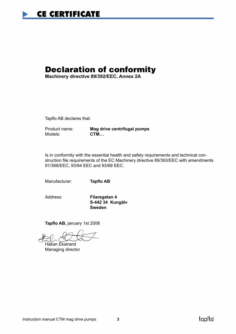
Declaration of conformityMachinery directive 89/392/EEC, Annex 2A
Tapflo AB declares that:
Product name: Mag drive centrifugal pumpsModels: CTM…
Is in conformity with the essential health and safety requirements and technical con-struction file requirements of the EC Machinery directive 89/393/EEC with amendments 91/368/EEC, 93/94 EEC and 93/68 EEC.
Manufacturer: Tapflo AB
Address: Filaregatan 4 S-442 34 Kungälv Sweden
Tapflo AB, january 1st 2008
Håkan EkstrandManaging director
CE CERTIFICATE

Instruction manual CTM mag drive pumps 4
0. GENERAL
0.1 IntroductionCTM is a compact and reliable magnetic drive centrifugal pump made in PP or PVDF. With proper attention to maintenance, CTM pumps will give efficient and trouble free operation. This instruction manual will familiarise operators with detailed information about installing, operating and main-taining the pump.
0.2 The warning symbolsThe following warning symbols are present in this instruction manual. This is what they say.
This symbol stands next to all safety instructions in this instruction manual where danger to life and limb may occur. Observe these instructions and proceed with ut-most caution in these situations. Inform also other users of all safety instructions. In addition to the instructions in this instruction manual, the general safety and accident prevention regulations must be observed.
This symbol signals possible danger caused by the presence of electric fields or live wires.
Danger magnetic field, indicates the presence of high intensity magnetic fields.
This signal stands at points in this instruction manual of particular importance for com-pliance with regulations and directives, for correct work flow and for the prevention of damage to and destruction of the complete pump or its subassemblies.
0.3 Qualification and training of personnelThe personnel in charge of installation, the operation cycle and maintenance of the pumps we produce must be qualified to carry out the operations described in this manual. Tapflo shall not be held responsible for the training level of personnel and for the fact that they are not fully aware of the contents of this manual.
STOP
!
STOP

Instruction manual CTM mag drive pumps 5
0.4 Description of the pumpThe CTM pumps are centrifugal, single-stage type with magnetic coupling, in close-coupled version, made from moulded thermoplastic material.
The main feature of these pumps is the transmission of movement by means of a magnetic coupling. The outer magnetic unit (16), connected to the motor shaft transmits torque to the inner magnetic core-impeller group (90), the magnetic field generates impeller rotation without physical contact. The isolation shell (12) is fitted between the two cores sealing hermetically the liquid pumped by the atmosphere, see figure below.
0. GENERAL

Instruction manual CTM mag drive pumps 6
0. GENERAL
0.5 Health & safety
Electric safetyDo not carry out any maintenance operation on the pump while it is running or before it has been disconnected from the power supply. Avoid any danger caused by electric power (for details see current regulations in force). Check that electrical specifications on the data plate are equivalent to the power supply to which it will be connected.
Chemical hazardsAvoid pumping liquids, even in different moments that may cause chemical reactions without having cleaned the pump.
Dry runningDo not start nor carry out running tests before filling the pump with liquid. Always avoid the dry operation of the pump. Start the pump when it is completely filled with the delivery valve almost fully closed, limiting this condition to the time that is strictly necessary to start the pump.
Temperature hazardsThe cold or hot parts of the machine must be protected to avoid accidental contacts.
Rotating partsDo not tamper with the protection of the rotating parts, do not touch or approach rotating parts in movement.
Noise levelCTM pumps, including the motor, in normal operating conditions produce a sound level below 80 dB(A). The major sources of noise are: liquid turbulence in the plant, cavitation or any other abnormal operation that do not depend from the pump construction nor the pump manufacturer. The user must provide suitable protective means if the sources of noise could produce a harmful noise level for operators and for the environment (in compliance with current regulations).
Powerful magnetic fieldMag-Drive pumps use wide range, high intensity magnets. All pacemaker carriers must not ap-proach magnetic components; intense magnetic fields can disturb heart pace.
SolidsIt is not recommended to use liquid with suspended solids, especially if sensitive to magnetism.In case dirty liquids are to be pumped and this was not mentioned at the time of ordering, it is necessary to contact Tapflo’s technical service before activating the pump.
Modifications and Spare partsAny changes concerning the service of the pump as originally purchased, can be executed only after written approval from Tapflo.It is recommended to use only genuine Tapflo spare parts and approved accessories. The use of non-original spare parts or non approved accessories will void warranty and removes any re-sponsibility on our behalf for any damage caused to people or things.
STOP
!
STOP
STOP
STOP
!
STOP

Instruction manual CTM mag drive pumps 7
1.1 Receiving inspectionAlthough precaution is taken by us when packing and shipping, we urge you to carefully check the shipment on receipt. Make sure that all parts and accessories listed on the packing list are accounted for. Immediately report any damage or shortage to the transport company and to us.
1.2 StorageIf the equipment is to be stored prior to installation, place it in a clean location. Do not remove the protective covers from the suction, discharge and air connections, which have been fastened to keep pump internals free of debris. Make sure to clean the pump thoroughly before installation.
1.3 FoundationThe pump-motor unit must stand on and be fixed to a sufficiently rigid structure that can support the entire perimeter on which the unit stands. The foundation on a firm bottom are the most satisfac-tory. Once the pump is in position, adjust level with metal shims between the feet and the surface on which it stands. Check that the feet of the pump-motor unit stand well on each of them. The surface on which the foundation stands must be flat and horizontal. If the unit is fitted on a steel structure, make sure that it is supported so that the feet do not warp. In any case, it is advisable to fit some antivibration rubber pieces between the pump and the brickwork.
As the pump is close-coupled type, pump-motor alignment is not required.
1.4 Piping connectionsA pump is generally part of a piping system that can include a number of components such as valves, fittings, filters, expansion joints, instruments, etc. The way the piping is arranged and the positioning of the components has a great influence on operation and the operating life of the pump. The pump cannot be used as a support for the components connected to it.
The flow of liquid from the pump must be as even as possible. It is advisable to avoid any tight bends or drastic reductions of diameters that may cause flow resistance in the plant. In case of diameter reduction, it is advisable to use appropriate conical reductions (possibly eccentric on suction side and concentric on delivery side) at changes of diameter and at a minimum distance from pump inlets of five diameters.
1.4.1 Discharge pipeA nonreturn valve and a shutoff/regulation valve are normally fitted on the discharge side.The nonreturn valve protects the pump from any backflow. The shutoff/regulation valve excludes the pump from the line and adjusts output. Never adjust flow-rate using the valve on the suction pipe.
1.4.2 Suction pipeThe suction piping is very important for the correct operation of the pump group. It must be as short and as direct as possible. If a longer suction line is unavoidable, the diameter should be large enough, i.e. at least as the inlet connection on the pump, to ensure less flow resistance. In any case, suction must be carried out properly avoiding any air locks.
The CTM pumps are single-stage centrifugal type, thus not self-priming. It will therefore always be necessary to install a bottom valve in all cases when the static height of the liquid is lower than the suction height of the pump. The suction piping must be without air inlets that are more probable with long suction lines or if suction occurs with negative head. Critical points in these terms are also the seals between flanges and the seals of the valve stems. Even some small air let into the suction line cause serious operating problems that can make the pump stop.
1. INSTALLATION
!
!
!
!
!
!

Instruction manual CTM mag drive pumps 8
1.5 Example of installation
1) YES: gate valve (may also be near pump in the case of long piping) 2) With positive head: tilt of piping towards pump 3) YES: line strainer if particles are present4) NO: air pockets: the circuit must be short and straight 5) YES: pipe fixing parts 6) Suction line as short and direct as possible7) YES: check valve (especially for long vertical or horizontal pipes; compulsory with parallel
pumps)8) YES: adjusting gate valve on outlet 9) Bends placed after valves and instruments10) YES: attachment for gauge or safety pressure switch 11) NO: elbow joints (and other parts) on the pump (discharge and suction lines)12) With negative suction lift: tilt of piping towards suction tank13) YES: check valve (with negative suction lift)14) YES: strainer if particles are present15) Suction head varies according to flow in order to prevent windage16) Suction head 17) Immersion depth18) YES: expansion joint (indispensable with long pipes or hot liquids) and/or anti-vibration facility
during discharge and suction; anchored near to pump19) YES: pipe discharge (completely sealed), discharge valve shut during normal operations20) YES: overcoming obstacles at lower depths21) Fix the pump by the fixing holes provided: the supports must be level 22) YES: drainage channel around base
1. INSTALLATION

Instruction manual CTM mag drive pumps 9
1.6 InstrumentsIn order to ensure a reasonable control of the performance and the conditions of the pump instal-led, we recommend using the following instruments:
- a pressure-vacuum gauge on the suction piping;- a pressure-vacuum gauge on the delivery piping.
The pressure intakes must be made on straight pieces of piping at minimum five diameters from the pump inlets. The pressure gauge on delivery must always be fitted between the pump and the shutoff/regulation valve. The output can be read on the pressure, transformed into meters and then compared with the typical curves.
Electric powerThe electric power absorbed by the motor can be measured with wattmeters.
Optional instrumentsThe optional instruments can advise of abnormal operating conditions of pumps, such as: valves closed accidentally, missing liquid, overloads, etc.
ThermometerIf the temperature of the pumped liquid can be a critical element, provide a thermometer (prefe-rably on suction).
1.7 Motor ConnectionAn expert electrician must always carry out the electrical connection. Compare the power supply with the data plate specifications and then choose a suitable connection. The type of connection is stated on the motor data plate that can be Y (star) or D (Delta), according to the power supply of the motor (see figure).
Star connection Y Delta connection D
Follow the prescriptions of the local electricity board for the connection. In no case connect the elec-trical motors directly to mains but also fit in between a suitable electric switchboard equipped with a knife switch and suitable safety devices. Safety devices against overloads must protect the motors. Make sure that the motor has suitable grounding and that it has been connected properly.
1. INSTALLATION
!
!

Instruction manual CTM mag drive pumps 10
2. OPERATION
2.1 Start-up
- Check manually that the motor is free to turn, moving the motor cooling fan.
- Make sure that the piping is not clogged and is free from residues or foreign objects. Make sure that the liquid flows regularly into the pump.
- The pump and piping connected to it, at least the suction pipe, must be full of liquid. Any air or gas must be carefully released. In case of suction with negative head, fill the suction piping and check how the bottom valve works. It must guarantee that the liquid must not flow back, emptying therefore the suction pipe with consequent disconnection of the pump.
- The suction shutoff valve (if any) must be completely open.
- The shutoff/regulation valve on the discharge side must be almost completely closed.
- The motor must turn in the same direction as the arrow shown on the pump. The direction of rotation is always clockwise looking at the pump from the motor side; check by starting briefly, then looking at the direction of rotation of the motor fan through the fan lid. If it is wrong, the motor must be stopped immediately. Change the connection to the terminals of the electric motor (chapter 1.7) and repeat the procedure described above.
- Any auxiliary connections must all be connected.
2.1.1 Starting the pumpStart the electric motor and open the discharge adjustment/shutoff valve gradually until the desired output has been reached. The pump must not turn more than two or three minutes with discharge closed. A longer operation in these conditions can damage the pump seriously.
If the pressure shown on the pressure gauge on the discharge piping does not increase, turn off the pump immediately and release pressure carefully. Repeat the connection procedure.
If there are changes of flow-rate, head, density, temperature or viscosity of the liquid, stop the pump and get in touch with our technical service.
2.1.2 Re-starting after power shutoffIn case of accidental stopping, make sure that the non-return valve has prevented backflow and check that the motor cooling fan has stopped. Start the pump again following the instructions of chapter 2.1.1 ”Starting the pump”.
If the pump intakes from a lower level, it can unprime during the standstill and therefore you must check again before starting that the pump and the suction piping are full of liquid.
2.2 Stopping the PumpIt is advisable to close the discharge adjustment/shutoff valve gradually and stop the motor im-mediately after. The reverse sequence is not recommendable, especially with larger pumps or longer delivery piping. That is to avoid any problems due to water hammering. If a suction shutoff valve has been installed, it is advisable to close it completely.
!
STOP
!
!
!
!

Instruction manual CTM mag drive pumps 11
3. MAINTENANCE
Maintenance work on electrical installations must be performed by qualified personnel and only when the power supply has been shutoff. Follow the local and national safety regulations.
3.1 Maintenance scheduleThe CTM range pumps have been designed and tested to run for 5000 hours in ideal working conditions.
Please note that is a conservative figure since the actual duty point of your pump can substantially modify such value. Additional factors such as intermittent operation, type of pumped liquid and installation in the plant may affect the life of components subject to wear.
In any case, Tapflo advises to service pumps every year of service, even when used in ideal operating conditions.
3.2 Trouble shootingThe following tables help to identify the causes of any problems during operation or failures of the pump. By consulting table ”A” identify on the left column (symptoms) the problem encountered on the right column (causes) the number relevant to the possible causes of malfunctioning. Table ”B”, by excluding the causes not applicable to the case being examined, allows to identify the causes of the problem.

Instruction manual CTM mag drive pumps 12
3. MAINTENANCE
Table A, identification of the problem
Problem Possible cause
Pump does not perform head required 1,2,3,4,9,10,11,12,14,15,17,18,19,24,29,32Insufficient flow rate 2,3,4,5,6,7,8,9,10,11,12,14,15,17,18,29,32Low delivery pressure 9,12,14,15,17,18,21,29Pump unmprimes after startup 2,3,4,9,10Leaks from pump 14,19,21,23,24,25,27,33Abnormal power absorption 13,16,17,18,21,23,24,25,26,28,30Vibrations and unnatural noises 2,3,6,7,9,10,11,16,19,21,24,26,27,28,29,30,31,32Bushing life too short 27,28,29,33The pump overheats 1,6,9,13,19,20,24,26,28
Table B, possible causes of the problem
1 The Pump is not primed2 Suction height too high3 Suction piping or pump not completely full of liquid4 Suction piping with air pockets5 Insufficient suction pressure6 Vapour pressure is too high7 Suction piping has too high friction losses 8 Insufficient suction head9 Too much air or gas in the pumped liquid10 Suction piping not sealed11 Bottom valve not sealed or clogged12 Low rotation speed13 High rotation speed14 Wrong direction of rotation15 The plant head is higher than the pump16 The plant head is lower than the pump17 Liquid with density differing from the expected one18 Liquid with viscosity differing from the expected one19 Operation without liquid -dry running- 20 Operating flow rate too low21 Operating flowrate too high -pump cavitates-22 Material not suitable for pumped liquid23 Pumped liquid with suspended solid substances24 Liquid temperature too high25 Liquid temperature too low26 Insufficient pressure or bushes flushing -lubrication-27 Shaft is not straight28 Static and rotating parts rubbing29 Damaged impeller30 Inner bushes worn or damaged31 Rotating unit out of balance32 Magnetic coupling damaged or insufficient33 Wrong assembly or with dirt
3.2.1 Trouble shooting tables

Instruction manual CTM mag drive pumps 13
3. MAINTENANCE
3.3 Assembly and disassembly
The assembly and disassembly should only be performed by qualified personnel.
Each operation carried out on the machine must always be carried out once all the electrical con-tacts have been disconnected. The pump-motor unit must be placed in a position where it cannot be started unintentionally.
Before servicing in any way the parts in contact with the pumped liquid, make sure that the pump has been fully emptied and washed. When draining the liquid, make sure that there is no danger for people or the environment.
3.3.1 Disassembly of the pumpFor dismantling the pump proceed as follows (see drawing below):
Dismantle the pump casing (13) from the lantern (11), by loosening screws (141) washers (142) and nuts (143).
Pull out the static bushing (1521) from the casing.
For CTM 20-7: remove the impeller magnet assembly (90) extract rotating bushing (1511) and rear bushing (1512) and the O-ring (1812).
For CTM 25-8 and 25-10: remove the impeller magnet assembly, extract rotating bushings (1511) and (1512) and the O-rings (1811) and (1812).
The static and rotating bushes are usually made from very fragile sintered material and therefore has to be handled with extreme care.
Remove the casing O-ring (18) from the isolation shell (12).
Extract the isolation shell (12) from the lantern (11).
Loosen the lock screws (161).
Remove the external magnet assembly (16) from the lantern (11) loosening the screws (111).
!
STOP
CTM 25-8CTM 25-10
CTM 20-7

Instruction manual CTM mag drive pumps 14
3. MAINTENANCE
3.3.2 Wear Parts Replacement
The components that can affect the correct operation of the pump if not regularly replaced, are:
CTM 20-7- Casing O-ring (18)- Rotating bushes (1511) + (1512)- Static bushes (1521) + (1522)- O-rings (1821) + (1812) + (1822)
CTM 25-8 and 25-10- Casing O-ring (18)- Rotating bushes (1511) + (1512)- Static bushes (1521) + (1522)- O-rings (1811) + (1821) + (1812) + (1822)
3.4 AssemblyTo re-assemble all the wet-end parts and the external magnet proceed in the reverse sequence.
3.4.1 Screws recommended locking torque
Part No Pump / Description Thread Locking torque (Nm)
141/143 CTM 20-7 / Screws and nuts M5 6111 CTM 20-7 / Screws M5 6 141/143 CTM 25-8 / Screws and nuts M6 9111 CTM 25-8 / Screws M5 6 141/143 CTM 25-10 / Screws and nuts M6 9111 CTM 25-10 / Screws M6 9

Instruction manual CTM mag drive pumps 15
4. SPARE PARTS
CTM 25-8CTM 25-10
CTM 20-7
4.1 Spare part drawing CTM pumps
4.2 Spare part list CTM pumps
Pos Description Pump model / qty Material 20-7 25-8 25-10
11 Lantern 1 1 1 PP-GF (30%)111 Motor mounting screw 4 4 4 AISI 30412 Isolation shell (rear casing) 1 1 1 PP-GF (30%) PVDF13 Pump casing 1 1 1 PP-GF (30%) PVDF141 Casing mounting screw 6 6 6 AISI 304142 Casing mounting washer 6 6 6 AISI 304143 Casing mounting nut 6 6 6 AISI 3041511 Rotating bushing front 1 1 1 PTFE-graphite SiC1512 Rotating bushing rear 1 1 1 PTFE-graphite SiC1521 Static bushing front 1 1 1 Al2O3 (ceramic) SiC1522 Static bushing rear 1 1 1 Al2O3 (ceramic) SiC16 External magnet assembly 1 1 1 Cast iron/NdFeB161 Lock screw 2 2 2 AISI 30418 Casing O-ring 1 1 1 EPDM FKM1811 O-ring - 1 1 EPDM FKM1812 O-ring 1 1 1 EPDM FKM1821 O-ring 1 1 1 EPDM FKM1822 O-ring 1 1 1 EPDM FKM90 Impeller magnet assembly 1 1 1 PP/NdFeB PVDF/NdFeB

Instruction manual CTM mag drive pumps 16
4. SPARE PARTS
4.3 Stocking recommendationDepending on the nature of the liquid and temperature etc, some parts of the pump are subject to wear and have to replaced. We recommend having the following parts in stock:
CTM magdrive centrifugal pump
Motor optionsblank* = 3-phase, 3x380V IP 55P = 1-phase motor
CTM 25-10 P 1V - 05 P 4
Material pump housingP = PP (polypropylene)K = PVDF (polyvinylidenefluoride)
Pump size(Outlet mm - impeller mm)20-725-825-10
Poles on motorblank* = 2 poles (~2900 rpm)4 = 4 poles (~1450 rpm)
Motor power01 = 0,12 kW (CTM 20-7)02 = 0,25 kW (CTM 25-8)05 = 0,55 kW (CTM 25-10)
* = Standard execution
Changes reserved without notice
Set 1 (2 years)
Pos Description Qty
1511 Rotating bushing front 11512 Rotating bushing rear 11521 Static bushing front 11522 Static bushing rear 1* Kit of O-rings 1
* = O-rings 18, 1811, 1812, 1821, 1822
4.4 Pump codeThe model number on the pump tells the pump size and material of the pump
Set 2 (5 years)
Pos Description Qty
12 Isolation shell 113 Pump casing 11511 Rotating bushing front 11512 Rotating bushing rear 11521 Static bushing front 11522 Static bushing rear 1* Kit of O-rings 1
Special options1 = Casing O-ringblank* = EPDM for PP pump, FKM for PVDF pumpE = EPDM (if used in PVDF pump)V = FKMK = FFKM
2 = Static bushingsblank* = Al2O3 (ceramic)S = SiC (silicone carbide)
3 = Rotating bushingsblank* = PTFE-graphiteS = SiC (silicone carbide)
4 = Connection optionsblank* = BSP external threadsF = Flanged DIN PN10 or ANSI 150

Instruction manual CTM mag drive pumps 17
5. DATA
5.1 Performance curvesThe performance curves are based on water at 20°C. Speed 2900 rpm. Contact us for detailed curves.
Changes reserved without notice

Instruction manual CTM mag drive pumps 18
5. DATA
Changes reserved without notice
5.2 Technical data and limits
DimensionsCTM 20-7 CTM 25-8 CTM 25-10
A 70 90 100
B 48 58.5 63
C 93.5 100.5 136.5
ØE 15 18 18
ØF 15 18 18
G 3/4” 1” 1”
H 3/4” 1” 1”
L 248.5 279 334.5
M 36 40 45
N 71 80 90
ØP 5.5 7 7
Q 56 63 71
R 35 39.5 43.5
S 90 100 112
T 112 126 141
MotorPower 0.12 kW 0.25 kW 0.55 kW
Size 56 63 71
Flange connections (optional)Inlet - DN25 DN25
Outlet - DN25 DN25
Dimensions in mm where other is not indicated
MaterialsPump casing and isolation shell (rear casing) PP (GF 30%) or PVDF
Impeller PP or PVDF
Lantern (not wetted) PP (GF 30%)
Static bushings Ceramic (standard) or SiC
Rotating bushings Carbographite (standard) or SiC
O-rings FKM (standard), EPDM or FFKM Kaflon
Magnets NdFeB
General characteristicsTemperature range PP pumps: 0°C .... +70°C
PVDF pumps: 0°C .... +80°C
System pressure rating PP pumps: PN4 at 20°C, PN2 at 70°C PVDF pumps: PN4 at 20°C, PN2 at 80°C
Viscosity 200 cSt max
Solids 2% max concentration in weightHardness 800 Vk / size 150 µm
Motor IEC standard, 3x380 VAC (other voltage upon request), 2900 rpm, IP55, frame B3/B14

Instruction manual CTM mag drive pumps 19
6. WARRANTY & REPAIR
6.1 Returning partsWhen returning parts to Tapflo AB please follow this procedure:
- Consult Tapflo AB for shipping instructions.
- Cleanse or neutralize and rinse the part/pump. Make sure the part/pump is completely empty from liquid.
- Pack the return articles carefully to prevent any damage under transport.
Goods will not be accepted unless the above procedure has been complied with.
6.2 WarrantyTapflo warrants products under conditions as below for a period of not more than 12 months from installation and not more than 24 months from date of manufacture.
1. The following terms and condition apply to the sale of machinery, components and related services and products, of Tapflo (hereinafter “the products”)
2. Tapflo (the manufacturer) warrants that:
a.) its products as being free of defects in material, design and workmanship at the time of original purchase;
b.) its products will function in accordance with Tapflo operative manuals; Tapflo does not guaran-tee that the product will meet the precise needs of the Customer, except for those purposes set out in any invitation to render documents or other documents specifically made available to Tapflo before entering into this agreement;
c.) high quality materials are used in the construction of the pumps and that machining and as-sembly are carried out to the highest standards.
Except as expressly stated above, Tapflo makes no warranties, express or implied, concerning the products, including all warranties of fitness for a particular purpose.
3. This warranty shall not be applicable in circumstances other than defects in material, design, and workmanship. In particular warranty shall not cover the following:
a.) Periodic checks, maintenance, repair and replacement of parts due to normal wear and tear (seals, O-rings, rubber items, bushings, etc..);
b.) Damage to the product resulting from:b.1.) Tampering with, abuse or misuse, including but not limited to failure to use the product for its
normal purposes as stated at the time of purchase or in accordance withTapflo instructions for use and maintenance of the product, or the installation or improper ventilation or use of the product in a manner inconsistent with the technical or safety standard in force;
b.2.) Repairs performed by non skilled personell or use of non original Tapflo parts b.3.) Accidents or any cause beyond the control of Tapflo, including but not limited to lightning,
water, fire, earthquake, and public disturbances, etc.;
4 The warrantee shall cover the replacement or repairing of any parts, which is documentedly faulty due to construction or assembling, with new or repaired parts free of charges delive-red by Tapflo. Parts subjected to normal tear and wear shall not be covered by the warranty. Tapflo shall decide as to whether the defective or faulty part shall be replaced or repaired.
5 The warrantee of the products shall be valid for a period in accordance to the current law from the date of delivery, under the condition that notice of the alleged defect to the products or parts thereof be given to Tapflo in written within the mandatory term of 8 days from the discovery.

Instruction manual CTM mag drive pumps 20
6 Repair or replacement under the terms of this warranty shall not give a right to an extension to, or a new commencement of, the period of warranty. Repair or replacement under the terms of this warranty may be fulfilled with functionally equivalent reconditioned units. Tapflo qualified personnel shall be solely entitled to carry out repair or replacement of faulty parts after careful examination of the pump. Replaced faulty parts or components will become the property of Tapflo
7 The products are built in accordance with standard CE normative and are tested (where app-licable) by Tapflo. Approval and tests by other control authority are for the customers account. The products shall not be considered defective in materials, design or workmanship if they need to be adapted, changed or adjusted to conform to national or local technical or safety standards in force in any country other than that for which the unit was originally designed and manufactured. This warranty shall not reimburse such adaptations, changes or adjustments, or attempt to do so, whether properly performed or not, nor any damage resulting from them, nor any adaptation, change or adjustments to upgrade the products from their normal purpose as described in the products operative manual without the prior written consent of Tapflo
8 Installation, including electric and other connections to utility mains according to Tapflo drawings, is for the cost and responsibility of the customer, unless otherwise agreed in writing.
9 Tapflo will not be liable on any claim, whether in contact, tort, or otherwise, for any indirect, special, incidental, or consequential damages, caused to the customer or to third parties, in-cluding loss of profits, arising by any possible infringement of par. 3 above or by the customer or third parties being in the impossibility of using the products.
Steady the above,Tapflo liability to the customer or third parties from any claim, whether in cont-ract, tort, or otherwise, shall be limited to the total amount paid by the customer for the product that caused the damages.
6. WARRANTY & REPAIR

Instruction manual CTM mag drive pumps 21
6. WARRANTY & REPAIR
Company:
Telephone: Fax:
Address:
Country: Contact name:
E-mail:
Delivery date: Pump was installed (date):
Pump type: Serial No (see name plate):
Description of the fault:
The installation
Liquid:
Temperature (°C): Viscosity (cPs): Spec. grav. (kg/m3): pH-value:
Contents of particles: %, of max size (mm):
Flow (l/min): Duty (h/day): No of starts per day:
Discharge head (mwc): Suction head/lift (m):
Other:
Place for sketch of the installation
6.3 Warranty form

Instruction manual CTM mag drive pumps 22
NOTES

Instruction manual CTM mag drive pumps 23
NOTES

DISTRIBUTOR:
Tapflo AB · Filaregatan 4 · S-442 34 Kungälv · SwedenTel (46) 303 63390 · Fax (46) 303 19916 · E-mail: [email protected] · www.tapflo.com