CT400 / CT410 - SATO America I/F emulates an IBM3287-2 printer with a standard Type A BNC connector....
8
CT400 / CT410 Plug & Play ) Q H – n a p a J ( r o C O T A S p n o i t a r o Printer ) e r o p a g n i S ( P ) S ( s c i n o r t c e l E O T A S e d o C r a B t d t L e y a l a M ( ) a i s O T A S r a B B n d S g n i l l e b a L & e d o C d h ) d n a l i a h T ( d t L , . o C ) d n a l i a h T ( O T A S e d o c r a B ) a n i h C ( d t L , . o C i a h g n a h S O T A S ) A S U ( O T A S m A , a c i r e . c n I m u i g l e B ( ) . V . N e p o r u E O T A S ) K U ( O T A S K U d t L m r e G ( a ) y n O T A S d n a l h c s t u e D H b m G ) d n a l o P ( O . O Z P S a k s l o P O T A S ) d n a l l o H ( m a d r e t t o R O T A S e r t n e C c i t s i g o L : y r o t c a F y a l a M ( ) a i s O T A S e d o C r a B S ) M ( s c i n o r t c e l E d h B n d ) a i s y a l a M ( S ) M ( s c i n o r t c e l E O T A S d h B n d Quick Guide 9001141B
Transcript of CT400 / CT410 - SATO America I/F emulates an IBM3287-2 printer with a standard Type A BNC connector....
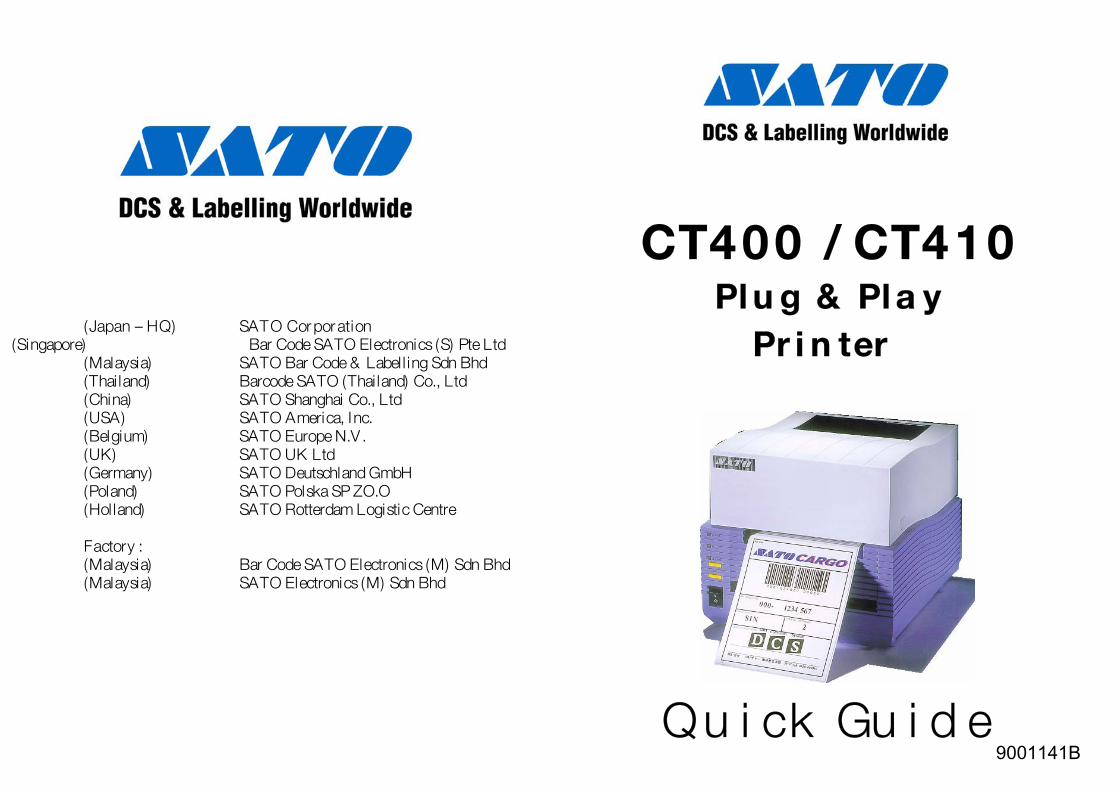
CCTT440000 // CCTT441100 PPll uu gg && PPll aa yy
)QH – napaJ( roC OTAS p noitaro
PPrr ii nn tteerr )eropagniS( P )S( scinortcelE OTAS edoC raB t dtL eyalaM( )ais OTAS raB B ndS gnillebaL & edoC dh
)dnaliahT( dtL ,.oC )dnaliahT( OTAS edocraB)anihC( dtL ,.oC iahgnahS OTAS
)ASU( OTAS mA ,acire .cnImuigleB( ) .V.N eporuE OTAS
)KU( OTAS KU dtLmreG( a )yn OTAS dnalhcstueD HbmG
)dnaloP( O.OZ PS aksloP OTAS)dnalloH( madrettoR OTAS ertneC citsigoL
: yrotcaFyalaM( )ais OTAS edoC raB S )M( scinortcelE dhB nd
)aisyalaM( S )M( scinortcelE OTAS dhB nd
QQuu ii cckk GGuu ii dd ee 9001141B
cynthiaj
Typewritten Text
WARNING THESE PRINTERS ARE SHIPPED WITH EITHER A 110 VOLT OR 220 VOLT POWER SUPPLY AS A CUSTOMER SPECIFIED OPTION. BEFORE CONNECTING A PRINTER TO ANY POWER SOURCE, ENSURE IT WAS FACTORY CONFIGURED FOR THE APPROPRIATE VOLTAGE. THE VOLTAGE FOR THE PRINTER DELIVERED MAY BE FOUND ON THE SHIPPING CONTAINER.
cynthiaj
Typewritten Text
cynthiaj
Typewritten Text
cynthiaj
Typewritten Text
cynthiaj
Typewritten Text
cynthiaj
Typewritten Text
CT4xx Series Quick Guide Pg 13
Options Label Cutter
This is an internal option allowing labels to be cut at specified intervals. Controlled through programming. Factory installed only. Bar Code SATO Electronics (S) Pte Ltd
438A Alexandra Road Label Dispenser #05-01/02 Alexandra Technopark Singapore 119967 Another internal option allowing labels to be peeled from backing for immediate (on demand) application. Factory installed only. Tel : (65) 6271 5300
Fax : (65) 6273 6011 Service Hotline : (65) 6273 6455 Label Rewinder
Email : [email protected] An external accessory that rewinds labels onto a roll after they are printed. Website : www.satosingapore.com
Serial Interface © Copyright 2001, 2011
Bar Code SATO Electronics (S) Pte Ltd High Speed RS232 interface option, 9600 to 57.6 Kbytes. Factory installed only. Ethernet Interface
TCP/IP Protocol Interface option. Factory installed only. USB Interface Warning : This equipment complies with the requirements in Part 15 of FCC rules for a Class A computing device. Operation of this equipment in a residential area may cause unacceptable interference to radio and TV reception requiring the operator to take whatever steps necessary to correct the interference.
Universal Serial Bus Interface option. Factory installed only. Coax/Twinax Interface
External Coax/Twinax I/F interface accessory. All rights reserved. No part of this document may be reproduced or issued to third
parties in any form whatsoever without the express permission of Bar Code SATO Electronics (S) Pte Ltd. The materials in this document are provided for general information and are subject to change without notice. Bar Code SATO Electronics (S) Pte Ltd assumes no responsibilities for any errors that may appear
Coax I/F emulates an IBM3287-2 printer with a standard Type A BNC connector. Twinax I/F emulates IBM 5224, 5225 or 4214 printers with auto-terminate / cable-thru capabilities.
cynthiaj
Typewritten Text
cynthiaj
Typewritten Text
WARNING BEFORE CONNECTING A PRINTER TO ANY POWER SOURCE, ENSURE IT WAS FACTORY CONFIGURED FOR THE APPROPRIATE VOLTAGE.
cynthiaj
Typewritten Text
Copyright (C) 2011 SATO America, Inc. 704-644-1660 Technical Support
cynthiaj
Typewritten Text

CT4xx Series Quick Guide Pg 12 CT4xx Series Quick Guide Pg 1 Printer Specifications Table of Contents
What You Get …………………………………………………………………... 2 Connecting The Printer ………………………………………………………... 3 Ribbon Loading (CT4xxTT only)……………………………………………… 5 Media Loading Roll Media ……………………………………………………………………... 5 Fanfold Media …………………………………………………………………. 7 Operator Panel …………………………………………………………………. 7 Rear Connector Panel ………………………………………………………….. 8 Troubleshooting Initial Checklist ………………………………………………………………... 9 Using the IEEE 1284 Parallel Interface ………………………………………... 9 Using the RS232C Serial Interface …………………………………………… 10 Error Signals ………………………………………………………………….. 11 Printer Specifications …………………………………………………………. 12 Options………………………………………………………………………….. 13 This Quick Guide was prepared to get you up and running quickly. It will enable you to get your new SATO CT4xx Series installed and printing with minimum effort. However, it is recommended that you familiarise yourself with the contents of the Printer’s Operator & Technical Reference Manual for detailed descriptions so you will be able to properly use the printer to its full potential.
The following is a general list of the CT400 / CT410 series specifications. For a complete listing, please refer to the Operator & Technical Reference, Section 1.
SPECIFICATION CT400 CT410PRINT Method Thermal Transfer or Direct Thermal
Speed (User Selectable) 2 – 6 ips 50 – 150 mm/s
2 – 4 ips 50 – 100 mm/s
Processor 32-Bit RISC, 80MHz Resolution 203dpi (8 dpmm) 305 dpi (12 dpmm) Maximum Print Length 15.6” (400mm) Maximum Print Width 4.1” (104mm) MEDIA Width 0.9” – 4.6” (23mm – 118mm) Minimum Length 0.6” (15mm) Roll OD (Maximum) 4.3” (110mm), Wound Face-Out
Label Sensing See-Thru for Labels & Tags, Reflective I-Mark, Continuous Forms
RIBBON Length 325 ft (100M)Maximum Width 4.4” (111mm) PRINT-OUTS
Text Fonts 12 Proportional & Mono-Spaced OCR-A & OCR-B 10 Scaleable Vector Fonts
Graphics Sato Hex/Binary, .BMP or .PCX Bar Codes 19 including Four (4) 2-D Bar Codes Rotation Text & Bar Codes can be rotated 90o, 180o & 270o PHYSICAL
Dimension W7.8” x D9.1” x H6.5” 198mm x 230mm x 181mm
Weight 6.6 lbs (3 Kg) POWER REQUIREMENTS Voltage 110V (± 10%); 220V (± 10%); 50/60Hz (±1%) Power Consumption 150W Operating at 30% Density ENVIRONMENTAL Operating 5 – 40oC; 30 – 80% RH, Non Condensing Storage -20 – 40oC; 20 – 90% RH, Non Condensing
CT4xx Series Quick Guide Pg 2 CT4xx Series Quick Guide Pg 11 6. If you are still unable to get printer output, try the Hex Dump as described in
Step 5 under the Parallel Interface troubleshooting. In this case, the printer monitors its RS232C interface for incoming data.
What You Get The CT Series Thermal Transfer printer comes packed in a protective carton. Included in the carton are the following items :
7. From the Hex Dump, if you are seeing no extra 0D 0A (CR & LF)
characters, and are using BASIC, refer to the beginning of the Command Code section. It provides hints for writing a SATO program in BASIC.
• CT400 / CT410 Printer
• Quick Guide Error Signals • Driver / Manual CD ROM The 7-segment LED, Front Panel LED Indicators and Buzzer provide a visual/audio indication of the type of error encountered.
• Power Module AC Power Cord
• Cleaning Solution & Cloth (Not for Export out of Singapore) LED Indicators Error Corrective Dis-
play LINE ERROR Buzzer Condition Action
0 ON 1 Beep Flash Memory error Replace Flash ROM
1 Not Assigned2 ON 1 Beep Motherboard error Replace PCB 3 ON 1Beep EEPROM error Replace EEPROM 4 ON 1 Beep Electrical Head Replace Print Head 5 Blink 3 Beeps Head not latched Latch Print Head
6 Blink 3 Beeps Out of Paper 1) Replenish paper 2) Route Paper thru sensor
7 Blink 3 Beeps Sensor error 1) Select correct sensor 2) Adjust sensor level
8 Blink 3 Beeps Cutter error Connect cutter
8. ON ON Program download error Retry download
9 Blink 3 Beeps Ribbon End (TT mode only) Replace ribbon
A ON 1 Beep Receive buffer overflow
1) Modify host SW 2) Select correct protocol
b ON 1 Beep Parity error (Serial I/F only) Correct Parity Settings
c ON 1 Beep Framing error (Serial I/F only) Correct data bit setting
d ON 1 Beep Overrun error (Serial I/F only)
Correct flow control settings
E ON 1 Beep LAN Time Out Error Replace LAN I/F
F 3 Beeps Download Font / Graphic Error Correct data stream

CT4xx Series Quick Guide Pg 3 CT4xx Series Quick Guide Pg 10 Connecting The Printer 6. When you send the print job to the printer and it does not respond, and
there is no error message on the PC : a. Check your data stream for some of the basics. Is your job framed as follows : 1. Locate a solid flat surface with adequate room to set the printer. Make sure
the Power Module can be located so that the power connecting the cable can be attached to the printer and the AC Power Cable can be connected to an AC power outlet.
<ESC>A--DATA--<ESC>Z b. Verify that you have included all required parameters in the data
stream. c. Verify the following : 2. The location should be near the host or computer terminal. The maximum distance is : i. You have not typed a ‘0’ (zero) for an ‘O’ (letter) or vice-versa.
ii. You have not missed any <ESC> characters where they are needed. - 10 feet for the Parallel interface. To fully utilise the capabilities of
the printer, a cable meeting IEEE 1284 specifications must be used. iii. Make sure all printer command codes are in Capital Letters. - 18 feet for the optional Serial RS232 interface. - 10 feet for the optional USB interface without hub. 7. If you have checked all of the above and the printer is still not printing, you may want to try a Buffer Hex Dump to determine what (if anything) the printer is receiving from your computer.
- The optional 10baseT Ethernet Interface depends upon the LAN cabling.
3. Make sure the power switch on the Operator Panel is in the OFF (0) position and place the Power Module in a safe and secure location, taking into consideration the location of the AC outlet and the host in relation to the printer.
Input Power Connector
Using the RS232C Serial Interface
1. Is the RS232C Serial Cable connected securely to your serial port on the PC (DB-25S or DB-9S Male) and to the RS232C connector on the printer?
2. Is the cable defective? At the very least, you should be using a “Null Modem Cable” which crosses pins in a specific manner. This should enable your printer to print. But we recommend that you eventually use a cable built to specifications as described in Section 5 of the Operator & Technical Reference Manual : Interface Specifications.
4. Connect the Input Power connector to the printer. This connector is keyed and must be turned approximately ¾ turn clockwise to secure it to the printer.
5. Connect the AC Power Cable to the proper AC Outlet supply. 3. Is the RS232 Interface option installed in the printer? DSW-8 must be in the OFF Position to enable the Optional Interface.
6. Connect the interface cable to the host system. A parallel IEEE1284 interface cable must be used to realise the high data transfer rate of the printer’s parallel port. If an optional interface is installed, the appropriate cable should be used.
Host IF Connector 4. Check for obvious errors in the data stream. Is the data properly framed
with the <ESC>A and <ESC>Z commands?
5. If after sending your job to the printer, it only “beeps’ and displays an error message of the 7-segment display, you may have a configuration problem. There may be some inconsistencies with the Baud Rate, Parity, Data Bits, or Stop Bits in relation to your host computer. If you are confused as to what the printer’s current RS232 settings are, print a self test label (refer to Section 2 of the Operator & Technical Reference Manual). It contains a list of all the current printer configuration settings.
7. Load the ribbon and media following the
instructions in the next section
8. Configure the printer for label width and operating mode by referring to the Operator & Technical Reference Manual – Section 2.

CT4xx Series Quick Guide Pg 4 CT4xx Series Quick Guide Pg 9 Troubleshooting 9. Apply power to the printer by placing the AC Power switch in the ON (1)
position. Initial Checklist 10. Print a test label to verify the printer is set up and operating correctly. 1. Is the Printer powered up and ONLINE? Ribbon Loading (CT4xxTT only) 2. Do any of the Front Panel LEDs indicate an error condition? If the Error
LED is lighted, it may mean the print head assembly is open. The SATO CT Series ribbons come shrink-wrapped with a 12” (305mm) leader pre-attached to a take-up core. There are 3 widths of ribbon available for the CT Series printers : 4.3” (110mm), 3” (76mm) & 1.75” (45mm).
1. Power off the printer.
2. Open the Top Cover by pressing the release
points located on each side of the printer. This releases the cover latch and allows it to swing upward on the rear mounted hinge points.
3. Release the Print Head Assembly by pressing the
Head Latch to the rear. This allows the assembly to rotate upwards to the left allowing easy access for ribbon routing. Rotate the assembly until it is vertical.
Head Latch
Ribbon Ass’y LatchRibbon Position
Button
3. Is the Print Head in the down and latched position?
Using the IEEE 1284 Parallel Interface
1. Is the IEEE 1284 printer cable connected securely to your parallel port (DB-25S Female) on the PC and to the Parallel Interface connector on the printer? Warning : Never connect or disconnect interface cables (or use a switch box) with power applied to either the printer or the host. This may cause damage to the interface circuitry and is not covered by warranty.
2. Does the Parallel interface cable used meet IEEE 1284 specifications? 3. Is there more than 1 parallel interface port on your PC (LPT1, LPT2,
etc.)? If so, make sure you are sending data out of the correct port. 4. Press down on the Ribbon Assembly Latch. This
allows the Paper Roller to swing downwards for ribbon routing.
5. Press down on the Ribbon Positioning button while
simultaneously pulling upwards on the Ribbon Spindle Unit, which should slide off.
Paper RollerRibbon Supply Spindle
Ribbon Take-Up Spindle
4. Is the IEEE 1284 interface selected? DSW-8 must be in the ON position
to enable the Parallel interface. 5. When you send the print job to the printer and it does not respond, do
you get an error message on your PC that says “Device Fault” or something similar? This may mean that the computer does not know the printer is there. Verify that : a. Both ends of the cable are securely inserted into their respective
connectors. 6. Remove the shrink-wrap from the ribbon and
unwind approximately 6” off the leader. Press the Ribbon Supply core all the way onto the rear spindle of Ribbon Spindle Unit. Press the attached take-up core on the front spindle. Make sure each core is fully seated on the spindles and there is enough ribbon leaders to go down around the print head
b. The printer is ONLINE c. The cable is not defective. There are other things that can cause this
error message on your computer, but at this stage, a defective cable may be one of the reasons.
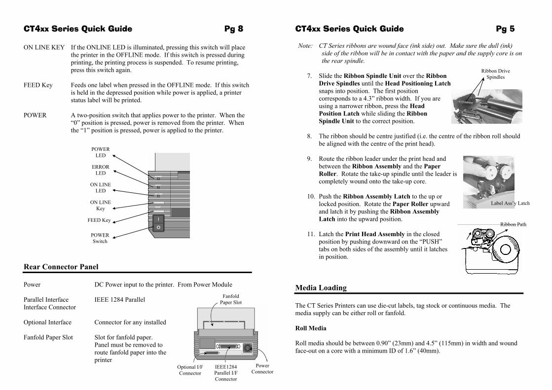
CT4xx Series Quick Guide Pg 5 CT4xx Series Quick Guide Pg 8 Note: CT Series ribbons are wound face (ink side) out. Make sure the dull (ink)
side of the ribbon will be in contact with the paper and the supply core is on the rear spindle.
ON LINE KEY If the ONLINE LED is illuminated, pressing this switch will place the printer in the OFFLINE mode. If this switch is pressed during printing, the printing process is suspended. To resume printing, press this switch again.
7. Slide the Ribbon Spindle Unit over the Ribbon Drive Spindles until the Head Positioning Latch snaps into position. The first position corresponds to a 4.3” ribbon width. If you are using a narrower ribbon, press the Head Position Latch while sliding the Ribbon Spindle Unit to the correct position.
Ribbon Drive Spindles
FEED Key Feeds one label when pressed in the OFFLINE mode. If this switch is held in the depressed position while power is applied, a printer status label will be printed.
POWER A two-position switch that applies power to the printer. When the
“0” position is pressed, power is removed from the printer. When the “1” position is pressed, power is applied to the printer.
8. The ribbon should be centre justified (i.e. the centre of the ribbon roll should be aligned with the centre of the print head).
ON LINE Key
POWER LED
ERROR LED
ON LINE LED
9. Route the ribbon leader under the print head and
between the Ribbon Assembly and the Paper Roller. Rotate the take-up spindle until the leader is completely wound onto the take-up core.
Label Ass’y Latch
10. Push the Ribbon Assembly Latch to the up or
locked position. Rotate the Paper Roller upward and latch it by pushing the Ribbon Assembly Latch into the upward position.
FEED Key
Ribbon Path 11. Latch the Print Head Assembly in the closed
position by pushing downward on the “PUSH” tabs on both sides of the assembly until it latches in position.
POWER Switch
Rear Connector Panel
Power DC Power input to the printer. From Power Module Media Loading
Fanfold Paper Slot
Parallel Interface IEEE 1284 Parallel Interface Connector The CT Series Printers can use die-cut labels, tag stock or continuous media. The
media supply can be either roll or fanfold. Optional Interface Connector for any installed Roll Media Fanfold Paper Slot Slot for fanfold paper.
Panel must be removed to route fanfold paper into the printer
Roll media should be between 0.90” (23mm) and 4.5” (115mm) in width and wound face-out on a core with a minimum ID of 1.6” (40mm).
Power Connector IEEE1284
Parallel I/F Connector
Optional I/F Connector
Route Paper under the Sensor
CT4xx Series Quick Guide Pg 6
1. Remove power from the printer by placing the Power
Switch in the OFF (0) position.
2. Open the Top Cover by pressing on cover release points located on each side of the printer.
3. Release the Print Head Assembly by pressing the Head
Latch to the rear. This allows the assembly to rotate upwards to the left allowing easy access for media routing. Rotate the assembly until it is vertical.
4. With the Print Head Assembly in the up position,
press the Paper Guide Release while adjusting the Paper Guides until they allow a media roll to fit between them. A millimetre scale is moulded into the case to provide a guide when making the adjustment. The Paper Guides are centre justified and interact with each other so that each moves an equal distance.
5. Make sure the Roll Holders are in the released
position. If they are not, lift up on each one and they will snap to the open position.
6. Unwind approximately 12” of label material from the
roll. The labels should be wound face-out (printing side to the outside of the roll). Drop the roll in between the Paper Guides so that the labels come off the top of the roll. The Paper Guides will automatically position the Roll Holders to suspend the roll.
7. Route the label material through the Paper Sensor
Assembly and over the Platen. Note that the Sensor is part of the left Label Roll Guide so that the Paper Sensor is always positioned in the same location relative to the left edge of the label.
8. Close and latch the Print Head Assembly.
9. Press the LINE key so that the printer is in the OFF LINE mode and then
press the FEED key. The label should advance to the next index (label gap or eye-mark) position.
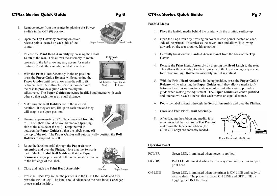
CT4xx Series Quick Guide Pg 7 Fanfold Media
1. Place the fanfold media behind the printer with the printing surface up.
2. Open the Top Cover by pressing on cover release points located on each side of the printer. This releases the cover latch and allows it to swing upwards on the rear mounted hinge points.
3. Carefully break out the Fanfold Access Panel from the back of the Top
Cover.
4. Release the Print Head Assembly by pressing the Head Latch to the rear. This allows the assembly to rotate upwards to the left allowing easy access for ribbon routing. Rotate the assembly until it is vertical.
5. With the Print Head Assembly in the up position, press the Paper Guide
Release while adjusting the Paper Guides until they allow a media to fit between them. A millimetre scale is moulded into the case to provide a guide when making the adjustment. The Paper Guides are centre justified and interact with each other so that each moves an equal distance.
6. Route the label material through the Sensor Assembly and over the Platten.
7. Close and latch Print Head Assembly.
8. After loading the ribbon and media, it is
recommended that you run a Test Print to make sure the labels and ribbon (for CT4xxTT only) are correctly loaded.
Operator Panel POWER Green LED, illuminated when power is applied. ERROR Red LED, illuminated when there is a system fault such as an open
print head. ON LINE Green LED, illuminated when the printer is ON LINE and ready to
receive data. The printer is placed ON LINE and OFF LINE by toggling the ON LINE key.
Platten Paper Sensor
Head Latch Paper Sensor
Paper Guide Release
Roll Holder
Millimetre Scale