=cT:--l--;::::; =: · ''''',.., - The Fu Foundation School ... · PDF fileNASA/HAMPTON...
11
• • NASA/HAMPTON REFUSE FIRED STEAM PLANT: A MUNICIPAL/FEDERAL COOPERATIVE EFFORT HUNTER F. TAYLOR Project Manager, Facility Design Richmond, Virginia DANIEL E. McCOY E. Keeler Company Will iamsport, Pennsylvania and HERBERT L. GREENE NASA - Langley Research Center Hampton, Virginia 6 " , ,, • " , . , . ·· . .. k .' . . , , � " . � . .. - ,� = cT-l: ;� = :�� £ · · ' '',. , ;��"" .. , •• . ' - \. �� " . . ,. . - 1 - - . , ' . l • • . '" ... \ , , � , " '. '1f'1'" , " lljl� 1 " � , . , • " It • I.' . , . , � , • • • • . . I. ' • • " • , • '� �. " . . . • .. � � .. � . . , � " , P ' . ' • • . . . . . . , . • -' . • . . , , ' , . � . . • - NASA REFUSE FIRED STEAM GENERATING FACILITY ABSTRACT This paper introduces a new MSW-fired steam plant scheduled to begin operation in Spring 1980, in Hampton, Virginia. The project is of interest for several reasons: 1. It is a joint venture between a federal agency seeking to decrease its consumption of fuel oil and a coastal city seeking an alternative to landfl dis- posal of its solid waste. 2. It uses source sizing to minimize fuel handl- 53 ing costs; its primary criteria are continual opera- tion and plant efficiency. 3. It is intended to demonstrate the feasibility of using 200 tons/day (182 tid) of MSW to gener- ate salable energy. Future papers will describe process operations; this paper wil l describe project objectives, design logic, process selection, and plant arrangement. INTRODUCTION In 1971, the National Aeronautics and Space
Transcript of =cT:--l--;::::; =: · ''''',.., - The Fu Foundation School ... · PDF fileNASA/HAMPTON...

• •
NASA/HAMPTON REFUSE FIRED STEAM PLANT: A MUNICIPAL/FEDERAL COOPERATIVE EFFORT
HUNTER F. TAYLOR Project Manager, Facility Design
Richmond, Virginia
DANIEL E. McCOY E. Keeler Company
Will iamsport, Pennsylvania
and
HERBERT L. GREENE NASA - Langley Research Center
Hampton, Virginia
6"
, ,, •
"
, ;, ..... , .. . ··tr . .. k
..
. ' .
.
,,� ..
" ...
� . .. - ,�
=c...T:--l--;::::;�=:��£. ·· ''''"',.. , ;���:��"" .... , ...... .., ••
. ' -\. ��
" .. , . . -
1 --- -. , ' .
l
• • . '" ..... \ , ,� \l., " .I .... '. '1f'1'" .• ," lljl�1 " � , . , • " It • I.' . , . ,� , • • • •
... I. ' •
•
"
•
, •
Ar"'� .. �. " .
.... • N" .. .. � � .. � . . , � "
, P' .' • •
. . . ....... . . ,. . • -..t' . • . ....... "!91
, , ' .'
, . � . .
•
-
NASA REFUSE FIRED STEAM GENERATING FACILITY
ABSTRACT
This paper introduces a new MSW-fired steam plant scheduled to begin operation in Spring 1980, in Hampton, Virginia. The project is of interest for several reasons:
1. It is a joint venture between a federal agency seeking to decrease its consumption of fuel oil and
a coastal city seeking an alternative to landfill disposal of its solid waste.
2. It uses source sizing to minimize fuel handl-
53
ing costs; its primary criteria are continual operation and plant efficiency.
3. It is intended to demonstrate the feasibility of using 200 tons/day (182 tid) of MSW to generate salable energy.
Future papers will describe process operations; this paper will describe project objectives, design logic, process selection, and plant arrangement.
INTRODUCTION
In 1971, the National Aeronautics and Space

Administration's (NASA) Langley Research Center (LaRC) initiated feasibility investigations to generate steam by burning refuse as part of their ongoing energy conservation demonstration program. As a result of these studies and rapidly rising energy costs, the Federal Government has joined in a cooperative effort with the City of Hampton, Virginia to implement a 200 tpd (182 tid) refusefired steam-generating facility.
The joint effort stems from two facts: 1. Hampton is a coastal peninsula with very
limited landftll capability. 2. The NASA/USAF facility in Hampton is
committed to reducing fuel oil consumption at its conventional steam plant.
Once concept feasibility was established, NASA was given the task of representing the Federal Government in negotiating contractual and financial arrangements with the City, and eventually for constructing the plant. The joint venture has resulted in a $10 million mass-fired, water-wall steam plant which is scheduled to start up in April 1980. Seventy percen t of the capital cost has been funded by the City which will own and operate the plant. The remaining 30 percent of the capital cost is being provided by the Government who will purchase all of the steam.
For purposes of refuse disposal, the facility will serve the City of Hampton, with a population of 140,000, and five nearby federal facilities. The steam and condensate lines from the refuse plant are tied in with those of the existing oil-fired plant which provides process and environmental steam for the NASA complex. When operating at its rated 66,000 lb/hr (29,900 kg/h), the plant will offset approximately 12,000 gal (45,400 I) of oil per day.
When the contractual arrangements were finalized in 1975, it was agreed that the City of Hampton would own and operate the plant. However NASA would provide the engineering effort to develop the design criteria and implement the facility design and construction.
OBJECTIVES
The project team began with one singularly significant goal: to design and build a state-of-theart plant requiring no auxiliary fuels and utilizing proven processes and equipment that would not require research and development to become
54
productive. It should be emphasized here that from the outset, the objective has been to build a steam generating plant that uses only municipal solid waste as a fuel rather than a solid waste incineration plant that recovers heat or generates steam in order to cool furnace walls. The difference is subtle, but worthy of recognition. This is a boiler plant project rather than solid waste disposal project.
Once the objectives were set forth, many manhours were expended investigating available options. NASA personnel from Langley Research Center visited incinerators, refuse burning steam plants, resource recovery facilities, pilot pyrolysis plants, and various other facilities all over the eastern half of the United States. They talked with consultants and equipment manufacturers from the United States and abroad. They attended seminars conducted by recognized experts in refuse disposal and energy/resource recovery.
As a result of these investigations, the NASA team identified the key problems pertaining to refuse combustion and established the design criteria aimed at achieving the project goals:
I. Maximize process availa bili ty. 2. Maximize overall thermal efficiency. 3. Minimize corrosion. 4. Maximize process control. 5. Minimize first and second costs. It was realized that, unlike the case with fossil
plants, far greater emphasis would have to be placed on process availability than on process efficiency. This is because refuse incineration plants experience far more unscheduled down-time than fossil fired plants, and a little increase in the overall process efficiency is insignificant compared to a few extra days of unexpected downtime.
Also, unlike a fossil plant, which can simply store fuel when not operating, the function of a refuse-fired steam plant is not only to generate steam, but to dispose of refuse. Naturally, a dual purpose process would have a greater emphasis on availability than a single purpose process would, and experience in existing plants indicates that availability is greatly compromised by materials handling systems, particularly refuse supply and ash removal. Thus, anything that can be done to minimize or simplify materials handling will improve availability. Also, those materials handling systems which are necessary for incineration should have standby systems or sufficient redundancy to preclude plant shutdown.
This emphasis on availability of material handling systems combined with the usual criteria of overall plant efficiency and low costs led to
the selection of mass-firing as the most attractive combustion method. This is not to say that massfired combustion is more available or thermally efficien t than suspension fi red com bustion, but rather that the overall availability, thermal efficiency, and costs of a 200 tons/day (182 tid) mass-fired plant are more attractive than those of a suspension fired plant. That is, the operating and maintenance costs for preparing 200 tons/day
(I82 tid) in a suspension fired plant is more than
can be offset by the lower excess air and grate
maintenance. Economic analyses indicated this to be true even if salvage revenues from recovered materials were included.
Once the decision was made to utilize massfiring, the alternatives for furnace design were:
1. Refractory set with waste heat boiler. 2. Packaged controlled air with waste heat
boiler. 3. Waterwall furnace with integral boiler. Since the first of these is not state-of-the-art
steam plant design and the second has not been demonstrated for a 200 tons/day (182 tid) plant generating 360 psig (2.6 MPa) steam, NASA selected mass-firing with waterwall furnaces.
In selecting the stoker, the emphasis on availability had to shift slightly. Although reciprocating grate stokers are not known for low maintenance, experience indicated that they offered good control and high burnout for less space and cost, so
they were selected as the optimum system. Further investigations led to the selection of
electrostatic precipitators for particulate emission control, overhead bridge cranes for refuse charging, mechanical chain conveyors for residue and fly ash removal, and many other features which have been proven successful in existing plants.
THE PLANT
REFUSE HANDLING
The refuse handling system is common for a mass-fired plan t. It does, however, include one innovative feature: A source sizing system to eliminate bulky items from the waste stream.
The key advantage of a mass-fired system is minimal energy and cost required for handling and
preparing fuel. At the same time, a mass-fired
55
plant with 100 tons/day (91 tid) boiler trains is particularly vulnerable to bulky items since overall clearances in the stoker and ash system are small. To insure availability, many mass-fired plants incorporate some sort of process or effort to separate bulky items from the fuel stream. Bulky items are usually shredded, sheared, or systematically rejected from the fuel stream after they are received at the plant. This adds to both the initial cost and the continuing cost of operation and maintenance of most mass-fired plants.
The City of Hampton has implemented a source
sizing collection system that will preven t bulky items from en tering the plant or from even being collected by those trucks which enter the plant.
All residents of the City of Hampton are required to discard their refuse in standard 80 gal (0.3 m3) cans. City collection crews will pick up refuse only from these standard cans at curbside with the top closed. Any refuse which will fit into this can will pass through the incinerator and the
ash handling system. No additional handling for bulky items is required at the plant. The only process between the packer truck and the incinerator is the usual overhead crane and grapple feeder. Also, since the standard cans have hinged lids, refuse will be dryer on rainy days. Packer trucks have been retrofitted with hydraulic devices specifically designed for lifting and dumping the heavy 80 gal (0.3 m3) cans.
Although the refuse/steam plant will not start up until 1980, the standard can collection system
has been in operation for several years. Mr. Frank Miller, Public Works Director for the City of Hampton, has stated that the system enables twoman crews to collect from more houses per day than three-man crews could previously collect, thus Significantly reducing collection costs. The City of Hampton has a separate system for collecting bulky items on residential routes.
After weighing, collection trucks en ter the enclosed tipping area of the steam plan t where all refuse is tipped into the refuse storage pit as shown in Fig. 1. The level volume of this pit up to the
tipping curb elevation is about 120,000 fe (3400 m3) which translates to about 700 tons (635 t) of refuse, a 3 day supply.
The refuse charging system is similar to that found in most mass-fired plants. An overhead crane with 5.5 ton (5 t) capacity and 3 cu yd (2.3 m 3) grapple retrieves refuse from the storage pit and feeds the charging hoppers of both stokers. The duty cycle analysis of the crane indicates that

Vl 0\
TIPPING fLOOR
5. 0 TON
REfUSE STORAGE
.ao TONS
FIG.1 FACILITY SECTION
TYPE OF PLANT
.... TElJIIAlS AECOVERY;
TYPE Of REFUSE
AUlllLLoUtY fUEL
eOillElllS
STOKERS
STU. UTILIZATION
P ROJECT COST
.06 tt/let
t
.unkAp_
W.t., •• 11 I rut.. & Tile
Itec:lproc.U,.,.
100� Proce .. ,( ..... _t ..
51.1 _1orI

r ,.r u- c:
c
REFUSE
STORAGE
ut 'tfI'P'NO FLOOR
Ul �
LJ1 '11 . ,
I> C
ru
h .fl-
mm
"
I I I t.:::::::: � .
I" '/ I I -. II I V SI
1111111
-
�
OfFICE
CONTROl
""""
..JL
SOlLER 2
•
1 B04lEA 1
ELECTRICAL
EQuiP. ROOtI
----,---- 1 1
, ------ ,. ,y I
1 -:: ::::- ::::�::O:::-_-_------· II
::--- � :"'" ,1\
;:' j '-'II ' t., , �
l-. , :\ : I '> .> ,j '. �
,
III � • •
r i:':i ,::' -- - ---- ', ' "
IL-,
TYPE Of PLANT ..... fired .... TERI ... lS RECOVERY: Non.
TYPE OF REFUSE
AUXlllAAY fUEl
BOREAS
Municipal --W.le,.aI' I Tube" Tile
STOKERS Rec:iprocatinG STEAM UTILIZATION 100� PToc: ... ,Enori,onmenl.1
PROJECT COST $ •. 8 Millon
FIG.2 FACILITY PLAN

both stokers can be fed at capacity rates in approximately 30 percent of the available time allowing 70 percent for operator fatigue, mishandling, and refuse mixing. A second crane identical to the first is available for standby service. The operating and standby arrangements for these cranes is shown in Fig. 2.
The redundancy offered by 2 cranes each with a 30 percent duty cycle coupled with the source sizing collection system serve to maximize process availability and minimize O&M cost associated with refuse handling and charging.
BOILER-STOKER
The boilers are top-supported, natural-circulation, single pass with a water cooled furnace. The boiler manufacturer supplied a complete package from the charging hopper through the economizer including the stoker, combustion air fans, and overfire air system. Basically, the boiler-stoker layout and design are very similar to other refuse' jobs by domestic boiler-stoker manufacturers that have been installed in this country.
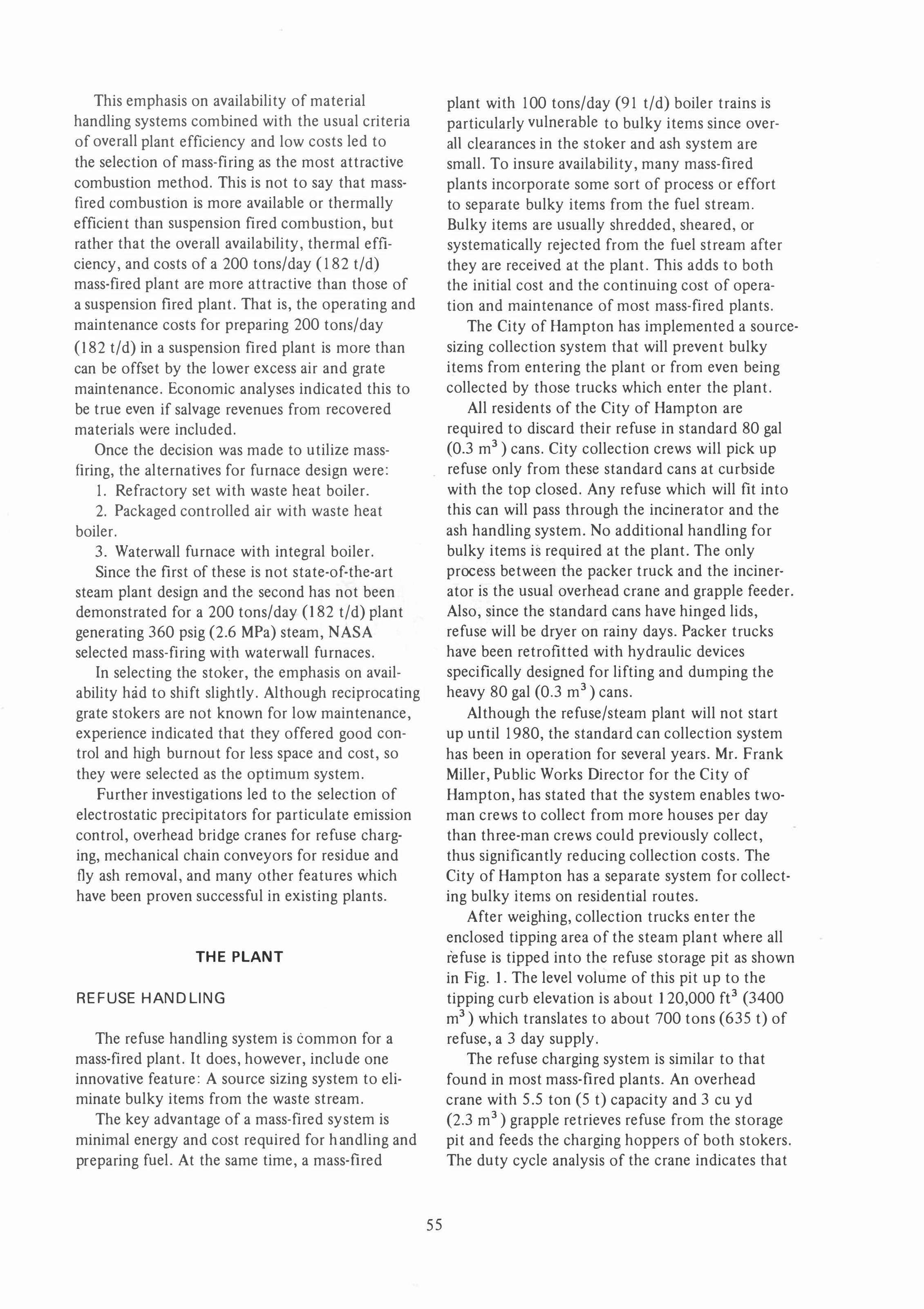
The refuse feeding system consists of a charging hopper, hydraulically operated cutoff gate, and a water cooled chute as shown in Fig. 3. The water cooled chute is arranged so that the material will drop vertically onto the first grate section and is fed to the furnace through a diverging cross-sectional area. Feed control of the refuse from the first grate section has been a problem on similar installations and the above design features were incorporated to eliminate sluggishness and the cascading of refuse into the furnace. During the early stages of the contract, a hydraulic ram-type feed was considered but limited operating experience, contractual considerations, and schedules precluded its use on this project.
The stoker is a 6 ft (1.81 m) wide, 3-section, reciprocating grate with a vertical drop between sections to provide mixing and break-up of the refuse. (Fig. 4). It includes a siftings removal system comprising a hopper under the first grate section and a reciprocating, pusher block system under the second and third grate sections. This system is powered by hydraulic cylinders, which are separate from the grate drives. The siftings are moved to the rear of the stoker and discharged into the ash removal system. The sifting discharge gates between the second and third grate sections and at the third section have been redesigned to permit continuous discharge of the full hopper flow area. This was done to reduce jamming by
58
such materials as springs and wires which may sift through the grates.
Since typical municipal refuse has a high percentage of volatiles, an extensive overfire air system is necessary for good combustion. TIle furnace frontwall and the bridgewall each have two levels of over fire air nozzles, and there are additional rows of nozzles on each sidewall immediately above the normal bed profile at the second grate section. The overfire air fans are located on the top floor of the boiler plant and arc equipped with dampers so that the normal operation will also provide plant ventilation.
Minimal corrosion was listed earlier as one of the design objectives. And even though combustion and boiler plant engineers have been battling corrosion since the industrial revolution, this problem has for the most part been a dew-point phenomenon in fossil fuel plants. However, with municipal refuse as the primary fuel - in this case the only fuel - corrosion problems are not as well understood, and the resulting metal wastage remains a key technical problem.
External waterwall corrosion in the lower furnace waterwalls has been experienced in this country as well as in Europe. There is some uncertainty as to the exact mechanics by which this corrosion occurs, but it has been generally accepted that the lower waterwall surfaces must be protected from the products of combustion. Further, it is believed that such protection is necessary at' least up to a level where one can be assured that the furnace atmosphere is consistently oxidizing, which would indicate wall protection to a level somewhere above the highest overfire air nozzles. Silicon carbide refractory has been select-
. ed as the tube protection material, because its comparatively high coefficient of heat transfer assists circulation (steam-water) in the furnace waterwall circuits and keeps the hot faced temperature of the refractory as low as possible to minimize slagging. In these furnaces, two types of silicon carbide material have been used. "Fired" shapes are used on each sidewall in the immediate fuel bed area, and silicon carbide castable has been applied on remaining areas to a height about 2 ft (0.6 m) above the highest level of overfire air nozzles. The "fired" shapes in the bed area are held in place by keying around the tubes and are easily replaceable. The castable was not used in the immediate bed area, because of its relatively poor abrasion resistance properties compared to "fi red" shapes.
•
•
•
•
tlCPPER
•
-
A1R •
MlHCIl'AL REFUSE - FIRED BOILER 0'''0.,.,. too .... flO QICt
•
•
•
•
• !
I J .. , • -,.� � • • • •
FIG.3 BOILER SECTION AL SIDE
59
•
',' J; •
-,. ( -------;' .----�
•
-�--
• . OUTLET
AIR
• •
ACCESS t 1
• • •
ASH - DISCHARGE
• " , . .�
•
•
" • •
•
•
• •
• •
• • • -::-..

FIG.4 STOKER SECTIONAL SIDE
The waterwall construction is typical of industrial practice for solid fuel fired boilers. The 3� in. (83 mm) tubes on 4� in. (114 mm) centers are backed by 2 in. (51 mm) of high duty refractory tile, 2 in. (51 mm) of block insulation and 3 in. (76 mm) of blanket insulation, with a 10 gauge (3.42 mm) completely welded outer casing. The furnace heat release is 13,300 Btu/fe
(495,800 kJ/m3) with a predicted furnace exit gas temperature of 1650 F (899 C) at rated capacity. The convection bank consists of 2 in. (51 mm) tubes on 4� in. (114 mm) side spacing and 4 in. (102 mm) inline back spacing providing a single pass design as shown in Fig. 3. The gas velocity throughout the bank is well below 20 ft/sec (6.1 m/s) and five retractable steam soot blowers provide bank cleaning.
Due to the steam flow fluctuations normally associated with mass refuse fired units and due to the number of tube rows, a liberal 60 in. (1.5 m) steam drum has been used. This will reduce water level stability problems tha t could result from fluctuating steam flows.
The economizer is shop assembled and consists of 2 in. (51 mm) bare tubes on 4� in. (114 mm) square pitch. The surface is arranged for upflow water and downflow gas with an exit gas tempera-
60
ture of 540 F (282 C) at rated capacity. Cleaning will be accomplished with two rotary steam soot blowers.
Fly ash from the two boiler hoppers and economizer hopper is returned continuously via rotary valves to the rear of the furnaces where it drops into the ash removal system.
CONTROLS
Another interesting feature of this plant is the process control system. One of the inherent drawbacks of mass-firing is poor process control. A burning heap of unprepared refuse is obviously not going to respond to steam load variations as well as prepared refuse which burns partly in suspension. However, since the steam output of the refuse plailt is tied into the steam distribution header of the existing oil fired plant; and, since the capacity steaming rate of the refuse boilers is less than the total steam demand of the combined system, the oil fired plant will remain in operation at all times and will therefore be available to respond to swings in the steam demand. Nevertheless, one of the design objectives is maximum process control, so a special effort was initiated to develop an
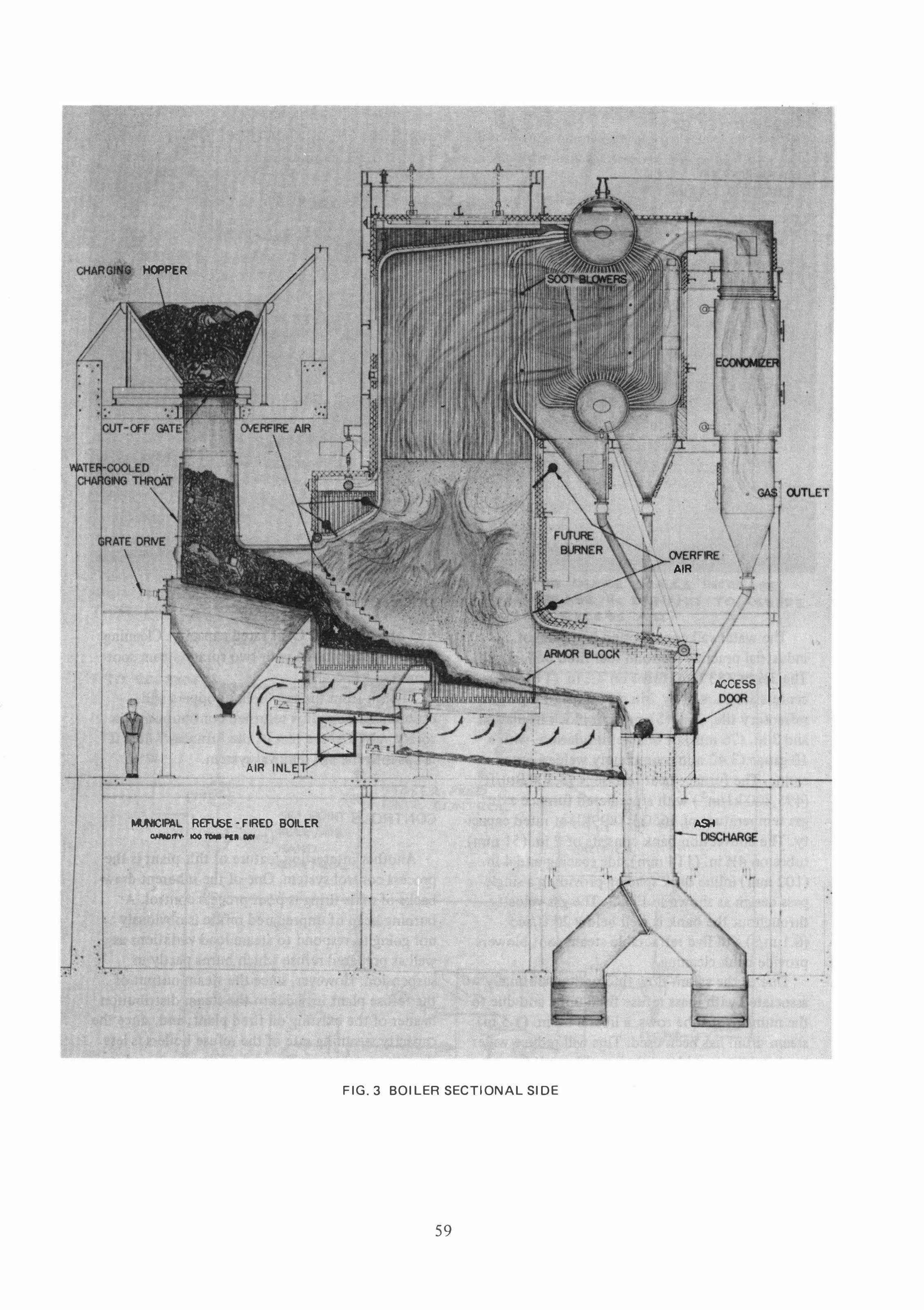
improved control scheme for mass-firing of municipal refuse. But since this plant will not start up until next Spring, detailed discussion of the control system is reserved for a future paper that will include operating data. For now, a brief description should be sufficient.
The process control scheme is an analog sys-tem comprising five basic control loops:
1. Three element feedwater.
2. Constant furnace pressure.
3. Stoker feed and underfire air. 4. Constant boiler pressure. 5. Heat release compensation. The first and second loops are common in
steam plants. Signals sensing steam flow and drum level are summed to provide a total feedwater control signal which is finally verified against the flow of feedwater su pply. And, constant furnace pressure is maintained by dual inlet box dampers on the induced draft fans. The combustion control system outlined as loops 3, 4, and 5, however, may be unique.
COMPUTIN� DE-VIce. '5E..\..E..CT5 H\(�H ':>I",NAL TO IMSUQjP THAT AIR L.AC:tS FU\:..\.. ---,
,0 1.0. FAN >
Figures 5 and 6 schematically show the operation of the combustion controls.
As previously mentioned, the refuse fired units will be base loaded to maintain a selected stearn flow and system load swings will be taken by existing oil units at the Langley Boiler Plant. The speed of the feed grate, (first section) and the under grate air supply will be modulated to maintain the selected steam flow. The second and third grate speeds will also be controlled by the same type signal as that sent to the first grate section, but the signal to these latter two grates will be trimmed by furnace exit gas temperature. The purpose of the furnace exit gas temperature trimming, which has been successfully used in the Chicago and Harrisburg plants, is to vary the stirring or stoking of the fire in order to maintain a fairly constant furnace exit gas temperature for a particular steam flow. Without this feature, the furnace exit gas temperature, which is indicative of steam generated, will vary considerably due to the nonhomogenous nature of the refuse.
,-- COMPUTING DE-VIC.E.. SC.ALE..S INC.RE..ASE.. 012. DE-C.RE ASE.. IN OE..Mlt.NO TO ASSURE.. PROI='E.Q. ElC.C.e.."!oS .... ,Q..
S TOlt.E..R FE.E.O RATE.. C.ONTROL.
I f----+ STE.AM
ORIFIC.E.. SE.T POIKT ��:H,"'" FI.IE.L / AIR
'-../ HAND ccm'Q.O\...
�. D. FAN
I ORifiCE.
e,OILU2. 4
FIG.5 COMBUSTION CONTROL
61

TO
ATMOS.
PIC�----------��----------�
SILOKUl..
TO LARC.
r---------�--------��--------------��----�-------SYSTEM
Sf 350 psig STEAM HEAOEl:l
FIG.6 BOILER STEAM PR ESSURE CONTROL
The combustion control signal to each of the three grates can be characterized and each has a biasing station to permit maximum flexibility for field adjustment at start-up and during operation.
In addition to the above combustion control features, the steam line from the refuse plant to the existing oil fired plant has a back pressure valve with atmospheric relief to assure a fairly constant pressure in the refuse plant steam header regardless of variations in the steam generated by the boilers (Fig. 6). This constant back pressure will enhance the water level stability characteristics of the boilers.
ASH HANDLING
The ash handling system is the usual scheme comprising water filled residue conveyors and dry mechanical chain fly ash conveyors. The bottom ash is discharged from the third gra te section directly into the residue conveyor troughs as shown in Fig. 3. Similarly, all of the fly ash is either discharged by gravity or conveyed mechanically from various collection points to the residue conveyors (Fig. 1). All of the ash is quenched as it is deposited into the residue trough and then mechanically conveyed into the ash hopper which is actually a truck. As with all ash handling systems, the main objective is to keep the system working, which is considerably more difficult in a mass-fired refuse plant than it is in a coal-fired plant. The bottom ash in this plant will literally contain any non-
62
combustible material or item which can be found in municipal refuse and which will pass through the system. As a result, residue conveyors must be very rugged and liberally designed; and they must include a standby system to minimize plant outages due to conveyor breakdowns. The bifurcated chute shown in Fig. 3 allows bottom ash to be discharged into either residue conveyor and the lower level fly ash conveyor provides the same choice for the fly ash discharge.
ENVIRONMENTAL
The two primary environmental considerations which must be formally addressed by the design effort of any new boiler plant are air quality at the stack outlet and water quality of all plant discharges.
The air quality criterion for these stacks is limited to particulate emissions. The maximum amount of particulates which can be emitted at any time is 0.08 grains/dscf (0.18 g/m3) corrected to 12 percent CO2, Compliance will be achieved with electrostatic precipitators which have been selected to emit no more than 0.05 grains/dscf (0.11 g/m3) for the gas flow rate and temperature produced ,with the boiler operating at a refuse input of 100 tons/day (91 tid) with refuse having a higher heating value of 5000 Btu/lb (I 1.6 MJ /kg) and 100 percent excess air. Model studies were conducted by the precipitator manufacturer for this particular application to insure adequate flow

TABLE 1 CONTR ACTUAL AND MAJOR EQUIPMENT PR OFILE
Major Effort or Component
Faci I ity Owner & Operator
Steam Customer
Process Design and Facility Implementation
Facility Design/Build Team
Waterwall Boilers (2-33,000 pph ea.)
R eciprocating Stokers (2-100 TPD ea.)
Process Controls
Charging Cranes (2-200 TPD)
Ash R emoval System
Electrostatic Precipitators (2) I. D. Fans (2) Double Wall Stacks
distribution and to verify the draft loss from economizer outlet to induced draft fan inlet.
The major water quality compliance problem associated with all solid fuel fired boiler plants today stems from ash-contaminated discharges. As just described, all of the ash collected in the plant is dumped into water filled residue conveyor troughs. Thus, the overflow from these troughs is sufficiently contaminated with ash to preclude legal discharge into the environment or sanitary sewer. Traditionally, solid fuel fired boiler plants, particularly the large power plants, have settling ponds to receive ash-contaminated flows; however, the real estate and maintenance effort required for ponds is almost prohibitive for small plants. Consequently, efforts to develop more attractive systems for processing ash discharges from industrial coal-fired boiler plants have produced some successful alternatives to settling ponds or large conventional clarifiers. One of these systems, which has been selected for this plant, utilizes a device known as a Lamella Gravity Settler to settle out suspended solids and recirculate the ash water. The major advantages of this system are lower capital costs and less space requirements. The Lamella settler has been suc
cessful in cleaning bottom ash sluicing water from coal-fired boiler plants, but it has never been em-
Supplier
City of Hampton, Virginia
U.S. Government
NASA - Langley R esearch Center
J. M. Kenith Co'/Wiley & Wilson, Inc.
E. Keeler Company
Detroit Stoker Company
Fisher Controls/D. W. Larcen & Co.
Harnischfeger-P&H
Beaumont Birch Company
Precipitair Pollution Control
Green Fan Company
Airtek Corporation
ployed on a refuse fired plant. Performance data on this system should be of interest in future papers.
In addition to the environmental problems associated with solid fuel firing, refuse plants must also contend with local odor, dust, and debris. In order to contain the odor and light debris within the enclosed tipping floor and refuse pit areas, the primary combustion air fans draw through grills located high on the refuse pit wall. Thus, normal boiler operation will simultaneously ventilate the front half of the plant, provide a slight negative pressure to contain odor and light debris, and incinerate the foul air created by the constant presence of the refuse.
CONCLUS ION
The NASA/Hampton plant will begin generating steam from municipal solid waste in 1980. In addition to providing energy required by NASA's Research Center while reducing its dependency on oil, it will dispose of 200 tons (182 t) of waste generated daily by the City of Hampton. Most
importantly, it should demonstrate to the nation's •
medium-sized cities that there is a feasible alter-native to sanitary landfill if they can develop a market for steam.
Key Words Boiler
Combustion
Electrostatic Precipitator
Heat
Incineration
Refuse
Waterwall
63