CSS Coolant Small System - davidsonsalesshop.com Manual.pdf · KIM HOTSTART Mfg., Co., Inc. P.O....
31
CSS Coolant Small System Installation & Operation Manual 216211-001
Transcript of CSS Coolant Small System - davidsonsalesshop.com Manual.pdf · KIM HOTSTART Mfg., Co., Inc. P.O....

CSS Coolant Small System
Installation & Operation Manual
216211-001

KIM HOTSTART Mfg., Co., Inc. P.O. Box 11245
Spokane WA 99211-0245
Customer Support: (509) 536-8660
NOTICE When ordering replacement parts for your heating system, always reference the heating system’s Model Number and Serial Number.

CAUTION ALL CONNECTIONS IN THE JUNCTION BOX SHOULD BE CHECKED PRIOR TO INSTALLATION. VIBRATION DURING SHIPMENT CAN CAUSE SCREWS TO LOOSEN. ALL CONNECTIONS IN THE JUNCTION BOX SHOULD BE CHECKED AT REGULAR INTERVALS. EXCESSIVE VIBRATION WILL EVENTUALLY CAUSE CONNECTIONS TO LOOSEN OVER TIME. WIRING TO HEATING SYSTEM TO BE PERFORMED BY A QUALIFIED ELECTRICIAN AND CONFORM TO ALL NATIONAL, STATE AND LOCAL ELECTRICAL CODES.
KIM HOTSTART MANUFACTURING COMPANY EAST 5723 ALKI AVENUE • P.O. BOX 11245 SPOKANE, WASHINGTON • 99211-0245 • USA Phone: (509) 534-6171 • Fax: (509) 534-4216

i
Notices This manual was prepared to assist you with the installation, operation and maintenance of the Kim Hotstart CSS Heating System. We encourage you to use this material and the enclosed illustrations as your primary source of information about the heating system. For additional information, contact:
Kim Hotstart Manufacturing Company P.O. Box 11245
Spokane, WA 99211-0245 Telephone: (509) 536-8660
Fax: (509) 534-4216 This instructional material and the corresponding illustrations are based on a typical Kim Hotstart heating system with standard components and the most frequently requested options. Your particular heating system configuration may vary from the heating system described. For your reference, available replacement parts and component options are listed in this manual.
Identifying Your “CSS” System The CSS Heating System is a compact coolant heating system designed for use in marine propulsion, diesel-powered generator sets, or any large engine applications. The model is pre-wired, pre-plumbed, and assembled on a steel plate. Each CSS heating system has an identification plate usually located on the front of the control box. An example of the identification plate is shown on the following page. NOTE: When ordering replacement parts, be sure to reference your heating system’s model and
serial numbers found on the identification plate. Model numbers ending in other than –000 are custom systems. Reference the drawings
included with your system for parts specific to your system.

ii

iii
Table Of Contents THE CSS SYSTEM...................................................................................................... 1-1
System Overview.................................................................................................................... 1-1
Basic System Operation......................................................................................................... 1-1
INSTALLATION AND SYSTEM START-UP ............................................................... 2-1
System Mounting Requirements .......................................................................................... 2-1
System Installation................................................................................................................. 2-3 Coolant Supply Line ............................................................................................................ 2-3
Coolant Discharge Line ....................................................................................................... 2-3
Main Power Wiring.............................................................................................................. 2-5
24 VDC System Shutdown .................................................................................................. 2-5
Electrical Grounding Requirements .................................................................................... 2-6
Coolant Requirements ........................................................................................................... 2-7
System Start-Up ..................................................................................................................... 2-8 Coolant Heating System Start-Up........................................................................................ 2-8
24 Volt DC Connection.......................................................................................................... 2-9

iv
SYSTEM COMPONENTS............................................................................................ 3-1
Control Box............................................................................................................................. 3-1 Fuses .................................................................................................................................... 3-2
Transformer.......................................................................................................................... 3-2
Coolant System Temperature Setting Adjustments ............................................................. 3-6
Coolant Heating Tank Assembly.......................................................................................... 3-3
Heating Element Replacement ............................................................................................. 3-4
Set Temperature Table.......................................................................................................... 3-7 SYSTEM MAINTENANCE & TROUBLESHOOTING .................................................. 4-1
System Maintenance .............................................................................................................. 4-1 Control Box.......................................................................................................................... 4-1
Plumbing Connections ......................................................................................................... 4-1
Electrical Connections ......................................................................................................... 4-1
Heating Tank........................................................................................................................ 4-2
System Mounting ................................................................................................................. 4-2
Troubleshooting ..................................................................................................................... 4-2 REPLACEMENT PARTS AND DRAWINGS ............................................................... 5-1
Replacement Parts ................................................................................................................. 5-1
Control Box Components...................................................................................................... 5-2
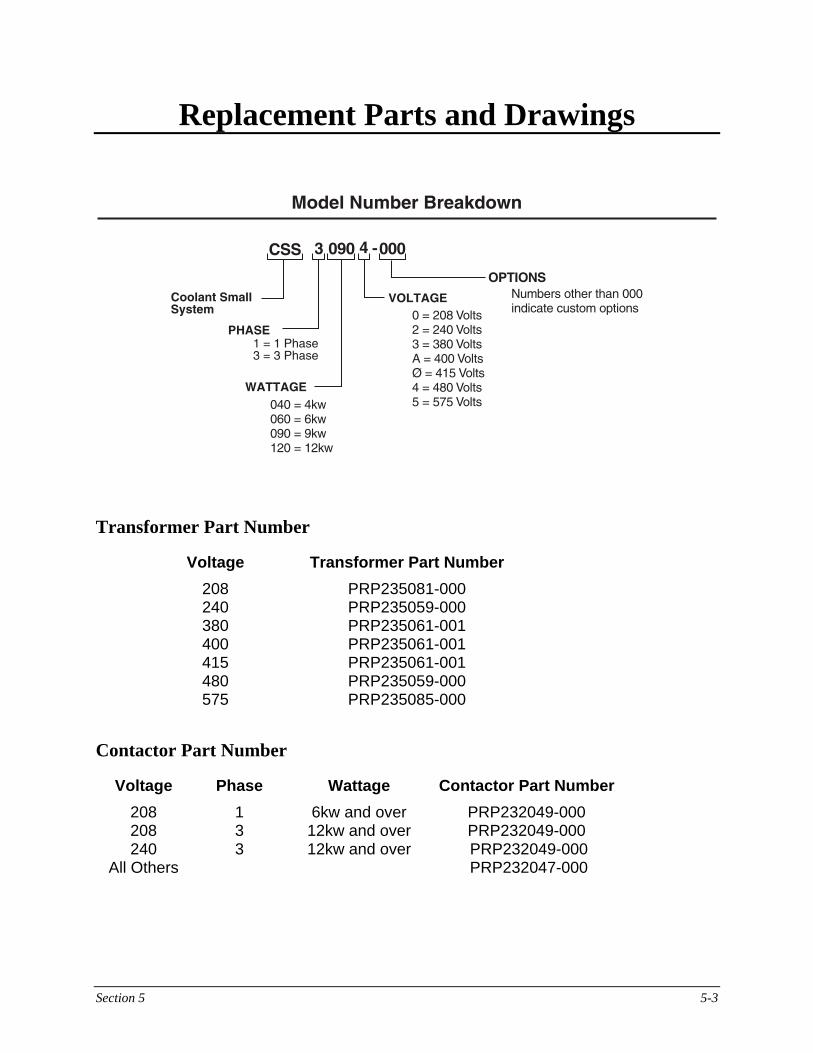
Model Number Breakdown................................................................................................... 5-3 Transformer Part Number .................................................................................................... 5-3
Contactor Part Number ........................................................................................................ 5-3
Wiring Diagram ..................................................................................................................... 5-4

Section 1 System Overview 1-1
The Kim Hotstart System System Overview
Shown on the next page is the basic layout of the CSS Heating System. This circulating heating system consists of a coolant heating chamber, heating element, adjustable thermostatic control, a centrifugal pump, a control box with electro-mechanical controls and a mounting plate.
Basic System Operation
Upon energizing the system, engine coolant which is taken from the coolant drain area in the lower section of the engine is circulated via a centrifugal pump, pulled through the heating chamber and back to a location on the engine furthest from the coolant suction line. The pump stays on and continues this circulation process even when the heating elements are off to provide an accurate, uniform heat to the engine. In the element enclosure is a thermister. This device senses the temperature of the engine coolant and sends a signal to a solid-state temperature controller in the control box that turns the element on and off as needed. The front panel on/off switch or a 24 VDC input for automatic operation can control system operation manually.

Section 1 System Overview 1-2

Section 2 Installation and System Start-Up 2-1
Installation and System Start-Up The Kim Hotstart Heating System comes pre-wired and pre-assembled for ease of installation. This section describes proper installation of the basic Kim Hotstart Heating System. Complete step-by-step instructions for system start-up are also included in this section. If you need additional assistance installing or starting your particular system application, please contact:
Kim Hotstart Manufacturing Company Customer Support (509) 536-8660
System Mounting Requirements The CSS Heating System can be mounted in the horizontal or vertical position. The pump shaft must be in the horizontal position at all times for proper lubrication and cooling of shaft end bearing. Be sure to mount the system as low as possible in reference to the engine coolant level. The outlet of the heating system is at the pump. Loosen the outlet flange to allow any trapped air to escape. This allows the heating tank to completely fill at all times, eliminating potential air pockets and thus preventing premature element failure. Heating Systems mounted on the engine’s skid base may require vibration isolators on the base plate to minimize excessive vibration to the system.
Vibration Isolator PRP220113-000 (Qty 4 required)

Section 2 Installation and System Start-Up 2-2
NOTE: The pump must be located at or below the water jacket level. Pump shaft must be
horizontal.

Section 2 Installation and System Start-Up 2-3
System Installation
Coolant Supply Line Connect a minimum 1-inch N.P.T. coolant supply hose or pipe from the main coolant drain of the engine to the tank inlet of the heating system. Drawing coolant from a location low in the coolant system will ensure head pressure to the pump. The supply line must remain level or angle downwards to eliminate air pockets. When approaching a plumbing obstacle, go around the obstacle instead of over it. Coolant Discharge Line Connect a minimum 1-inch N.P.T. coolant return hose or pipe from the outlet of the pump to the highest possible location on the engine coolant system at the furthest possible location from the suction line. This connection enables heated coolant to be circulated through the entire engine. NOTE: Your system may be configured with optional, non-restrictive shut-off valves in the
coolant lines allowing maintenance on the heating system without draining the engine coolant.
Isolation Valves PRP203125-100 NOTE: If the heating system is plumbed with rigid pipe, use flexible lines near the heating
system long enough to provide freedom from vibration in all directions. NOTE: After the heating system is mounted and refilled with coolant, loosen outlet flange
at pump to bleed the air out of the system.

Section 2 Installation and System Start-Up 2-4
Coolant return line to rear of engine.
engcool.eps
Engine
CoolantOutlet
Optional Shut-Off Valve
Optional Check Valve
CoolantInlet
CSS System

Section 2 Installation and System Start-Up 2-5
Main Power Wiring Connect the specified voltage and phase to the terminal blocks located in the main control box of the Heating System. A user-supplied circuit breaker should be used rated at the appropriate amperage. For 3 phase applications, the terminal blocks are labeled L1, L2 and L3. For single phase applications, use terminal blocks labeled L1 and L3.When a power transformer is required, the main power supplies the primary side of the transformer and heating element. The transformer, used to operate the control circuit, drops the main supply voltage to 120V and operates the coolant pump. The transformer, control circuit and pump are overload protected with fuses. 24 VDC Shutdown Connect an engine-supplied source of 24 VDC electricity to the terminal blocks labeled A and B in the control box. When present, this 24 VDC shutdown signal will disable the heating system to prevent operation while the engine is running.

Section 2 Installation and System Start-Up 2-6
Electrical Grounding Requirements Proper equipment grounding to the Kim Hotstart Heating System protects against electrolytic corrosion and coolant system damage caused by electrical current. It is essential that you check for voltage potential in the cooling system; 0.5 volts will destroy a cast iron engine. For testing, you will need a voltmeter capable of reading A.C. and D.C. voltage in tenths of a volt. Meter leads must be long enough to reach between the ground side of the battery and the coolant system. To test voltage potential in the cooling system, follow these steps: Step 1 Turn the Kim Hotstart Heating System OFF. Step 2 Attach the proper meter lead to the ground side of the battery. Step 3 Install the second lead in the coolant. Be sure the lead touches the coolant
only. Step 4 Read the A.C. and D.C. voltage with all systems turned OFF. Step 5 Turn the Kim Hotstart Heating System ON and take an A.C. and D.C. voltage
reading. Step 6 Read the A.C. and D.C. voltage with the electrical starter engaged. Step 7 Take voltage readings with the engine running and all associated electrical
systems turned ON. Step 8 Remove the test lead from the coolant. Rest the lead against the outside of the
engine block. Repeat steps 4 through 7. Step 9 If you detect a voltage in the engine coolant system, change the coolant.
Electrical current destroys the iron protective chemical in a properly inhibited coolant.
Step 10 Correct the source of stray voltage by use of proper grounding.

Section 2 Installation and System Start-Up 2-7
Coolant Requirements Upon an initial coolant fill and each subsequent replacement, check the quality of the source water. Proper coolant management procedures can eliminate engine and heating system problems. Use these guidelines:
Basic Water Quality
Chlorides Sulfates Total Hardness Total Solids pH
50 PPM Max 50 PPM Max 100 PPM Max 250 PPM Max 7,5 to 10.5
To achieve the level of quality required, it may be necessary to use distilled water (not deionized). Distilled water is corrosive without proper inhibitors. Kim Hotstart Manufacturing also recommends use of a well-inhibited ethylene glycol cooling solution at 30% to 60% ratio. Glycol based inhibitors provide superior corrosion protection, inhibition, a lower freeze point and an increased boiling point. For heavy duty engines, use a low silicate coolant formula inhibitor composition with a silicate level of no more than 230 PPM. This coolant fill is supplemented with an inhibitor additive package to provide specific inhibition for wet sleeve cylinder liners, cavitation, pitting and erosion. NOTE: The use of glycol still requires non-corrosive water, periodic re-
inhibition and inhibitor monitoring. Kim Hotstart Manufacturing recommends use of "Fleetguard DCA4" (or equivalent), a high quality inhibitor package that provides excellent steel, aluminum, copper and other cooling system metals protection for the pre-heating system and engine. DCA4 formula consists of a balanced combination of phosphate, molybdate and nitrite inhibitor, and is packaged in units for easy calculation of coolant amounts.

Section 2 Installation and System Start-Up 2-8
System Start-Up After system installation has been completed, follow these steps for proper Coolant Heating System start-up. Coolant Heating System Start-Up
CAUTION: DO NOT START THE PUMP BEFORE FILLING THE SYSTEM WITH COOLANT AND NEVER OPERATE THE PUMP DRY.
Step 1 Check and tighten all electrical and plumbing connections. Step 2 Ensure isolation valves are open before starting system. Step 3 Once the heating system is installed and the engine is filled, run the engine for
a short period before energizing the heater. This will purge any air from the pump and heating tank. Loosen outlet flange at pump to bleed air.
Step 4 The thermostat is set at 65° from the factory for initial start-up. Energize the
coolant heating system by turning the coolant switch on the control box to the ON position. After flow is verified through the tank and any trapped air is expelled, adjust thermostat to the desired temperature. See pages 3-7.
NOTE: On initial startup, it may take several attempts to achieve proper flow. If the Coolant Heating System fails to operate correctly, contact Kim Hotstart Manufacturing at (509) 536-8660 for further instructions.

Section 2 Installation and System Start-Up 2-9
24 VDC Connection A terminal block, labeled A and B , for the 24 VDC input signal is supplied inside the control box of the Kim Hotstart heating system. The signal source for this connection is usually the fuel pump or alternator. Once the signal is detected at the control circuit, the heating system will automatically shut down during engine operation and re-energize upon engine shutdown.
CAUTION THE HEATING SYSTEM MUST NOT BE OPERATED WHILE THE ENGINE IS RUNNING. IF OPERATED, PREMATURE ELEMENT FAILURE MAY RESULT.

Section 3 System Components 3-1
System Components This section describes the control box and heating tank components of the CSS Heating System. Control Box The control box used in the Kim Hotstart Heating System is shown. The control box contains the electrical control components of the heating system. Parts in the control box may vary, depending on the particular system configuration you purchased.

Section 3 System Components 3-2
Fuses There are one or two different types of fuses located in the control box depending on the heating system: Transformer Primary Fuses These fuses, located in the control box, protect the power transformer from overloading. Transformer Secondary Fuse This fuse, located in the control box, protects the control circuit components of the
control box and the pump. Transformer The transformer steps down the source primary voltage to 120 volts. Wiring information is listed on the top of the transformer. This transformer is overload protected with fuses. NOTE: When ordering replacement parts, be sure to reference your heating system's
model and serial numbers found on the identification plate.

Section 3 System Components 3-3
Coolant Heating Tank Assembly The Kim Hotstart coolant heating tank assembly is shown below.
Following is an overview of operation and replacement instructions for the CSS heating tank assembly and components, including the coolant heating element.

Section 3 System Components 3-4
Heating Element Replacement The heating element heats the engine coolant. To replace the heating element, follow the steps on the following page. Be sure to allow at least 12" of space for element removal. The wattage and phase of the heating element are listed on the identification label found on the base of the heating element assembly.
WARNING DISCONNECT ALL POWER AT THE SOURCE LEADING TO THE KIM HOTSTART
HEATING SYSTEM PRIOR TO PERFORMING ANY MAINTENANCE ON THE HEATING SYSTEM.

Section 3 System Components 3-5
Step 1 Turn the Kim Hotstart Heating system OFF.
Step 2 Drain the fluid from the heating
tank. Step 3 Open the element enclosure and
disconnect the following wires to the heating element assembly:
• L1, L2, L3 (L1 & L3 on single
phase units) • The 2 wires from the thermister. • The heating element ground wire. Step 4 Remove the conduit connector and
electrical wires from the element enclosure.
Step 5 Remove the heating element by
loosening the clamp from the heating tank as shown.
Step 6 Replace the heating element or
perform the necessary cleaning procedure.
To re-assemble the heating element and tank, follow the steps listed above in reverse order. Make sure the green ground and black power electrical wires are properly reconnected. To order a new heating element, refer to part number on the label of the element, or the assembly drawing included with this manual.

Section 3 System Components 3-6
Coolant System Temperature Setting Adjustments The system temperature setting adjustment is located inside the control box. The solid-state adjustable thermostat provides 5° incremental settings between 65° and 140°. To adjust the heating system's temperature, follow these steps.
CAUTION DISCONNECT ALL POWER AT THE SOURCE PRIOR TO PERFORMING ANY
MAINTENANCE TO THIS HEATING SYSTEM. Step 1 Open the control box. Step 2 Inside the control box, locate the thermostat control with four dip switches. Step 3 The system's temperature setting is factory preset at 65°F for initial start-up.
After flow is achieved a setting of 100° under normal conditions is sufficient for normal operation. If a higher or lower temperature is required, reset the dip switches to desired temperature.
CAUTION SEE SET-TEMPERATURE TABLE ON PAGE 3-8 FOR ORIENTATION OF THE
COMBINED SWITCHES THAT ARE NUMBERED 1, 2, 4 AND 8 LOCATED ON TOP OF THE SOLID-STATE CONTROL.
After the desired temperature is achieved, close the control box and re-energize the heating system. A few seconds will pass before the thermostat control begins to energize the element.

Section 3 System Components 3-7
Set Temperature Table

Section 4 4-1
System Maintenance & Troubleshooting This section describes maintenance procedures for the Kim Hotstart Small Capacity Heating System and provides tips for troubleshooting. System Maintenance The following maintenance procedures are provided to ensure trouble-free operation of your heating system: • Control Box • Plumbing Connections
• Electrical Connections • Heating Tank
• System Mounting
WARNING DISCONNECT ALL POWER PRIOR TO PERFORMING ANY SYSTEM
MAINTENANCE. Control Box ! Periodically check O-rings and gaskets for proper seals.
! Check the control box for moisture (if necessary, add desiccant packets).
Plumbing Connections
! Periodically check plumbing connections for leaks and, if necessary, tighten connections. A loose connection on the suction side will cause a loss of flow.
Electrical Connections
! Excessive vibration will eventually cause terminals to loosen. Periodically tighten all electrical connections. Ensure that all connectors to the circuit board are firmly seated.
! At least once every six months, spray the inside of the main control box with a moisture
repellent for electrical connections.

Section 4 4-2
Heating Tank
! At least once per year, clean the interior of the heating tank and the heating element with a wire brush and/or damp cloth. Periodically check the element for sediment build-up around the hairpins. Any scaling or build-up will shorten element life. Maintenance and replacement procedures for the heating element are described in Section 3.
System Mounting ! Excessive vibration may cause mounting bolts to loosen. Periodically check and
tighten all mounting bolts.
Troubleshooting
Symptoms Possible Causes Solutions
Air leaks in suction lines Tighten suction line connections
No power Energize main power supply
Blown fuses Replace primary and/or secondary fuses
Isolation valves are closed (user supplied) Open isolation valves
Coolant is not heating
Thermostat is not set properly Adjust thermostat dip switches inside control box

Section 5 5-1
Replacement Parts and Drawings
Replacement Parts Description Part Number
Pump PRP228052-001 Tank Clamp PRP215113-000 Flange Pump PRP213009-001 O-Ring Pump PRP203093-000
Note: For element Part Number, add “RE” to the front of the System Part Number.
Example: RECSS30604 All Dimensions on Reference

Section 5 5-2
Replacement Parts and Drawings
Control Box Components Description Part Number
On/Off Switch PRP231075-002 Fuse – 600v/2amp PRP231068-002 Pilot Light PRP231004-002 Snubber PRP224098-000 Temp. Control PRP224096-001 Relay – 24v PRP224047-001 Transformer See p. 5-3 Contactor See p. 5-3
Section 5 5-3
Replacement Parts and Drawings
Transformer Part Number Voltage Transformer Part Number
208 PRP235081-000 240 PRP235059-000 380 PRP235061-001 400 PRP235061-001 415 PRP235061-001 480 PRP235059-000 575 PRP235085-000 Contactor Part Number Voltage Phase Wattage Contactor Part Number
208 1 6kw and over PRP232049-000 208 3 12kw and over PRP232049-000 240 3 12kw and over PRP232049-000 All Others PRP232047-000

Section 5 5-4
Replacement Parts and Drawings Wiring Diagram