CSET 4650 Field Programmable Logic Devices Dan Solarek VHDL Additional Details & Examples.
61
CSET 4650 CSET 4650 Field Programmable Logic Devices Field Programmable Logic Devices Dan Solarek Dan Solarek VHDL VHDL Additional Details & Additional Details & Examples Examples
-
Upload
victor-sparks -
Category
Documents
-
view
220 -
download
0
Transcript of CSET 4650 Field Programmable Logic Devices Dan Solarek VHDL Additional Details & Examples.
CSET 4650 CSET 4650 Field Programmable Logic DevicesField Programmable Logic Devices
Dan SolarekDan SolarekDan SolarekDan Solarek
VHDLVHDLAdditional Details & ExamplesAdditional Details & Examples
2
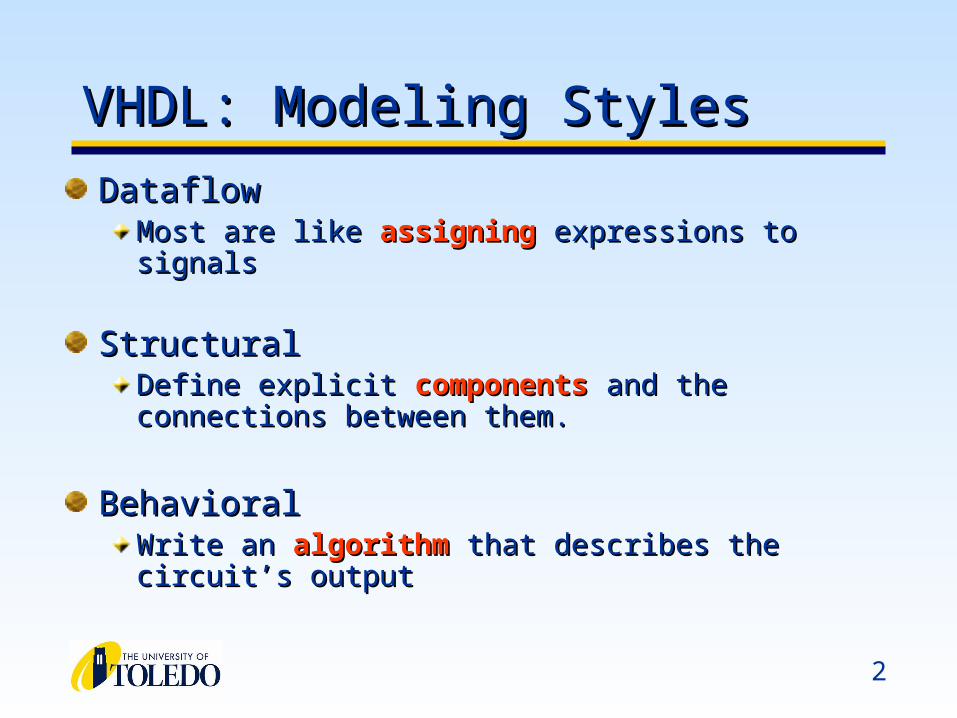
VHDL: Modeling StylesVHDL: Modeling Styles
DataflowDataflowMost are like Most are like assigningassigning expressions to signals expressions to signals
StructuralStructuralDefine explicit Define explicit componentscomponents and the connections between and the connections between them.them.
BehavioralBehavioralWrite an Write an algorithmalgorithm that describes the circuit’s output that describes the circuit’s output
3
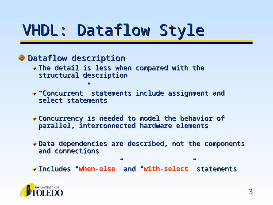
VHDL: Dataflow StyleVHDL: Dataflow Style
Dataflow descriptionDataflow descriptionThe detail is less when compared with the structural descriptionThe detail is less when compared with the structural description
““Concurrent” statements include assignment and select statementsConcurrent” statements include assignment and select statements
Concurrency is needed to model the behavior of parallel, Concurrency is needed to model the behavior of parallel, interconnected hardware elementsinterconnected hardware elements
Data dependencies are described, not the components and Data dependencies are described, not the components and connectionsconnections
Includes “Includes “when-else” and “” and “with-select” statements” statements
4
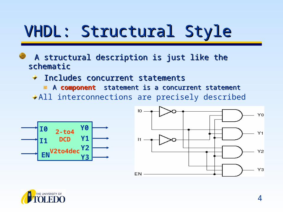
VHDL: Structural StyleVHDL: Structural Style
A structural description is just like the schematicA structural description is just like the schematic
Includes concurrent statements Includes concurrent statements A A componentcomponent statement is a concurrent statement statement is a concurrent statement
All interconnections are precisely described
2-to4DCD
V2to4dec
I1
I0
EN
Y0
Y1Y2Y3
5
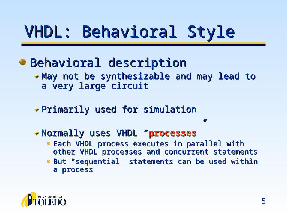
VHDL: Behavioral StyleVHDL: Behavioral Style
Behavioral descriptionBehavioral descriptionMay not be synthesizable and may lead to a very large May not be synthesizable and may lead to a very large circuitcircuit
Primarily used for simulationPrimarily used for simulation
Normally uses VHDL “Normally uses VHDL “processesprocesses””Each VHDL process executes in parallel with other VHDL Each VHDL process executes in parallel with other VHDL processes and concurrent statementsprocesses and concurrent statementsBut “But “sequentialsequential” statements can be used within a process” statements can be used within a process
6
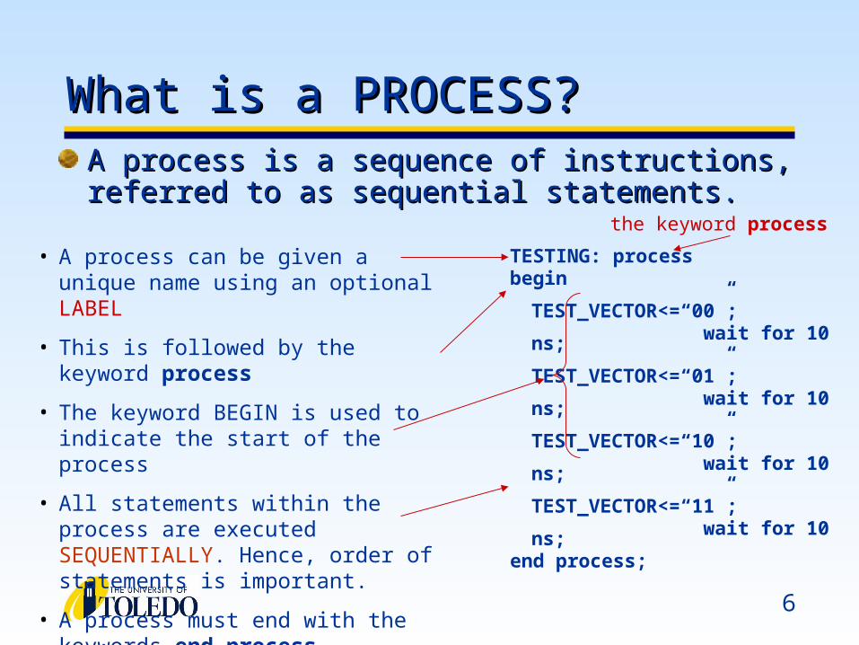
• A process can be given a unique name using an optional LABEL
• This is followed by the keyword process
• The keyword BEGIN is used to indicate the start of the process
• All statements within the process are executed SEQUENTIALLY. Hence, order of statements is important.
• A process must end with the keywords end process.
TESTING: process begin
TEST_VECTOR<=“00”;wait for 10 ns;
TEST_VECTOR<=“01”;wait for 10 ns;
TEST_VECTOR<=“10”;wait for 10 ns;
TEST_VECTOR<=“11”;wait for 10 ns;
end process;
A process is a sequence of instructions, referred to A process is a sequence of instructions, referred to as sequential statements.as sequential statements.
What is a PROCESS?What is a PROCESS?
the keyword process
7
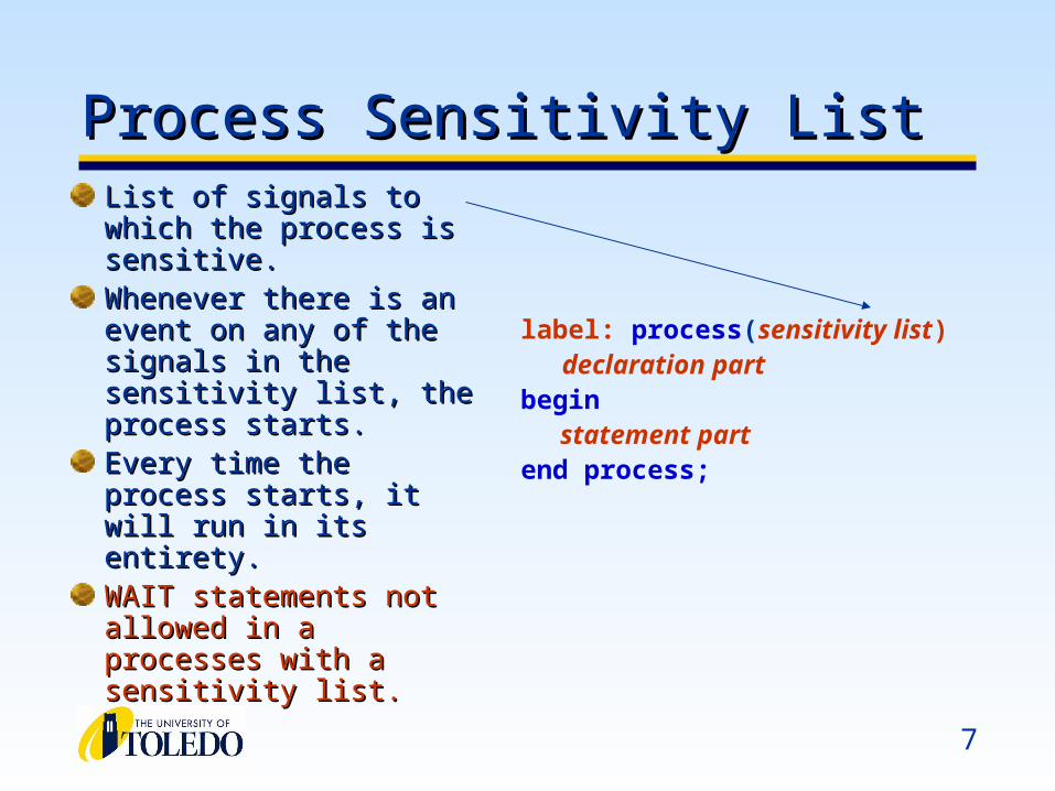
Process Sensitivity ListProcess Sensitivity ListList of signals to which List of signals to which the process is sensitive.the process is sensitive.Whenever there is an Whenever there is an event on any of the signals event on any of the signals in the sensitivity list, the in the sensitivity list, the process starts.process starts.Every time the process Every time the process starts, it will run in its starts, it will run in its entirety.entirety.WAIT statements not WAIT statements not allowed in a processes allowed in a processes with a sensitivity list.with a sensitivity list.
label: process(sensitivity list) declaration part begin
statement part end process;

8
VHDL ProcessesVHDL Processes
• Processes Describe Sequential BehaviorProcesses Describe Sequential Behavior• Processes in VHDL Are Very Powerful StatementsProcesses in VHDL Are Very Powerful Statements
• Allow to define an arbitrary behavior that may be difficult to Allow to define an arbitrary behavior that may be difficult to represent by a real circuitrepresent by a real circuit
• Not every process can be synthesizedNot every process can be synthesized
• Use Processes with Caution in the Code to Be Use Processes with Caution in the Code to Be SynthesizedSynthesized
• Use Processes Freely in TestbenchesUse Processes Freely in Testbenches
9
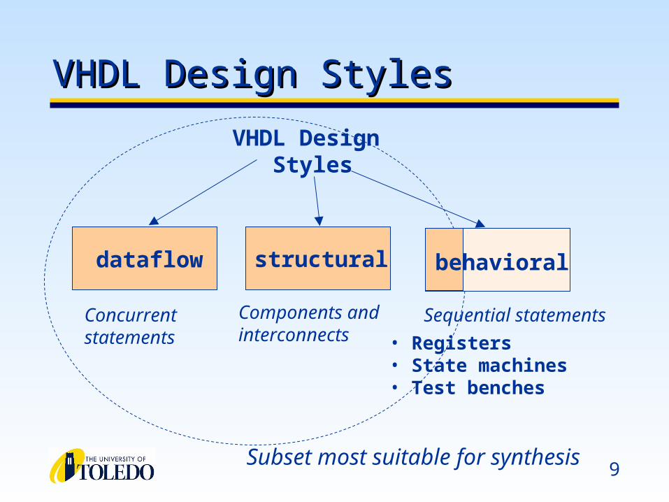
VHDL Design StylesVHDL Design Styles
Components andinterconnects
structural
VHDL Design Styles
dataflow
Concurrent statements
behavioral
• Registers• State machines• Test benches
Sequential statements
Subset most suitable for synthesis

10
VHDL Details: Design FlowVHDL Details: Design Flow
VHDL VHDL compilercompiler analyzes code for syntax errors and analyzes code for syntax errors and checks for compatibility with other moduleschecks for compatibility with other modulesSynthesizerSynthesizer converts VHDL program to a circuit with converts VHDL program to a circuit with components components Place and routePlace and route fits the circuit to a device fits the circuit to a device
Elements of VHDLElements of VHDL
12
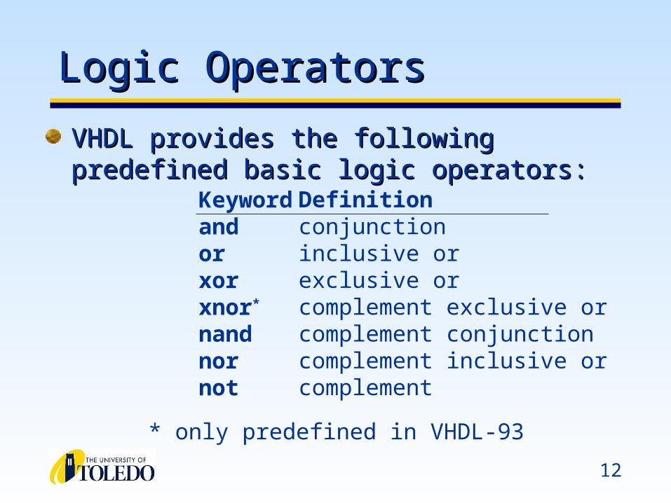
Logic OperatorsLogic Operators
VHDL provides the following predefined basic logic VHDL provides the following predefined basic logic operators:operators:
Keywordandorxorxnor*
nandnornot
Definitionconjunctioninclusive orexclusive orcomplement exclusive orcomplement conjunctioncomplement inclusive orcomplement
* only predefined in VHDL-93
13
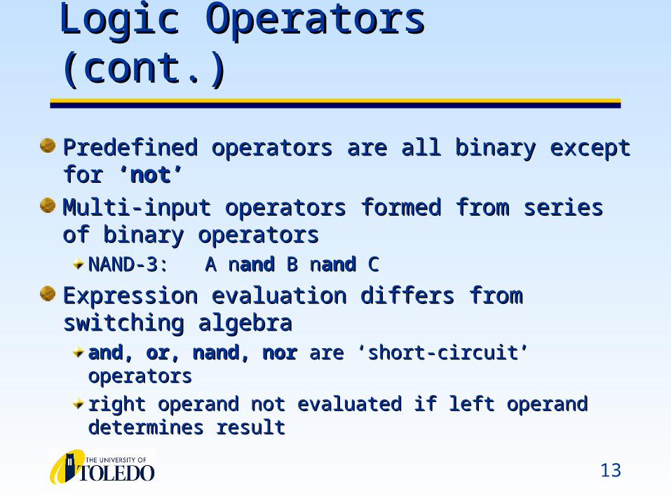
Logic Operators (cont.)Logic Operators (cont.)
Predefined operators are all binary except for Predefined operators are all binary except for ‘not’‘not’
Multi-input operators formed from series of binary Multi-input operators formed from series of binary operatorsoperators
NAND-3:NAND-3: A nA nandand B n B nandand C C
Expression evaluation differs from switching algebraExpression evaluation differs from switching algebraand, or, nand, norand, or, nand, nor are ‘short-circuit’ operators are ‘short-circuit’ operators
right operand not evaluated if left operand determines right operand not evaluated if left operand determines resultresult
14
Operator PrecedenceOperator Precedence
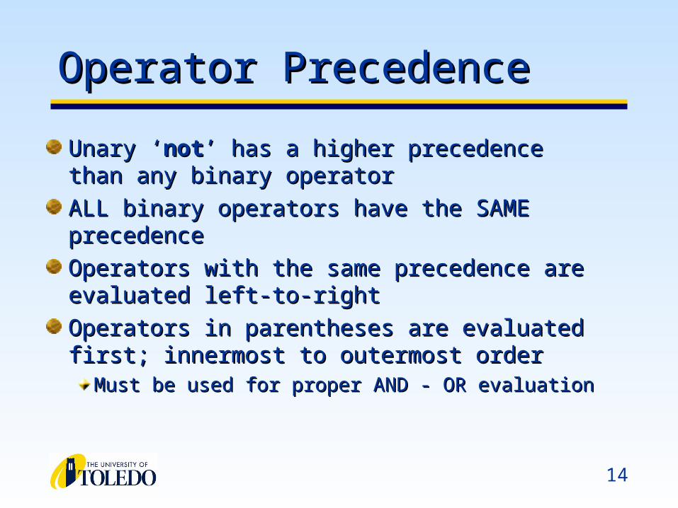
Unary ‘Unary ‘notnot’ has a higher precedence than any ’ has a higher precedence than any binary operatorbinary operator
ALL binary operators have the SAME precedenceALL binary operators have the SAME precedence
Operators with the same precedence are evaluated Operators with the same precedence are evaluated left-to-rightleft-to-right
Operators in parentheses are evaluated first; Operators in parentheses are evaluated first; innermost to outermost orderinnermost to outermost order
Must be used for proper AND - OR evaluationMust be used for proper AND - OR evaluation
15
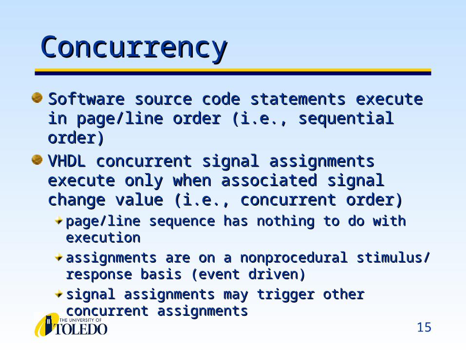
ConcurrencyConcurrency
Software source code statements execute in page/line Software source code statements execute in page/line order (i.e., sequential order)order (i.e., sequential order)
VHDL concurrent signal assignments execute only VHDL concurrent signal assignments execute only when associated signal change value (i.e., concurrent when associated signal change value (i.e., concurrent order)order)
page/line sequence has nothing to do with executionpage/line sequence has nothing to do with execution
assignments are on a nonprocedural stimulus/ response assignments are on a nonprocedural stimulus/ response basis (event driven)basis (event driven)
signal assignments may trigger other concurrent signal assignments may trigger other concurrent assignmentsassignments
16
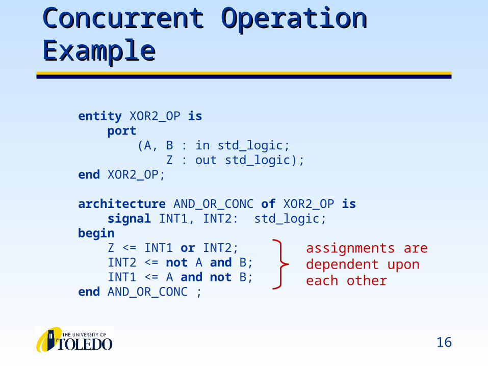
Concurrent Operation ExampleConcurrent Operation Example
entity XOR2_OP is port (A, B : in std_logic; Z : out std_logic);end XOR2_OP;
architecture AND_OR_CONC of XOR2_OP is signal INT1, INT2: std_logic;begin Z <= INT1 or INT2; INT2 <= not A and B; INT1 <= A and not B;end AND_OR_CONC ;
assignments are dependent upon each other
17
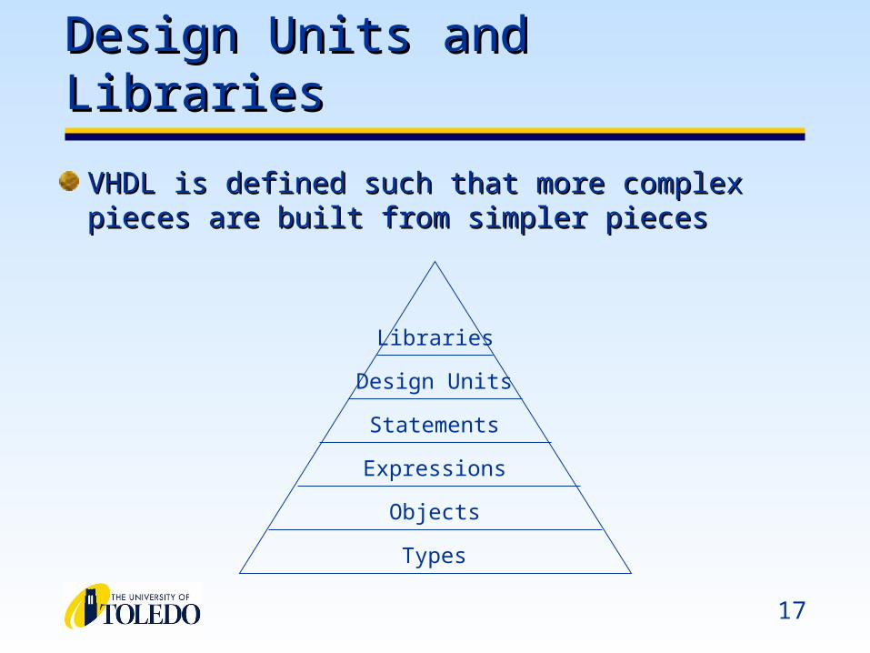
Design Units and LibrariesDesign Units and Libraries
VHDL is defined such that more complex pieces VHDL is defined such that more complex pieces are built from simpler piecesare built from simpler pieces
Libraries
Design Units
Statements
Expressions
Objects
Types
18
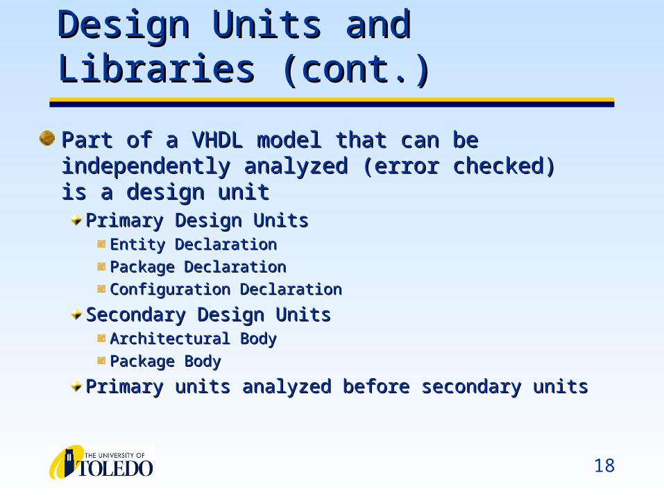
Design Units and Libraries (cont.)Design Units and Libraries (cont.)
Part of a VHDL model that can be independently Part of a VHDL model that can be independently analyzed (error checked) is a design unitanalyzed (error checked) is a design unit
Primary Design UnitsPrimary Design UnitsEntity DeclarationEntity Declaration
Package DeclarationPackage Declaration
Configuration DeclarationConfiguration Declaration
Secondary Design UnitsSecondary Design UnitsArchitectural BodyArchitectural Body
Package BodyPackage Body
Primary units analyzed before secondary unitsPrimary units analyzed before secondary units
19
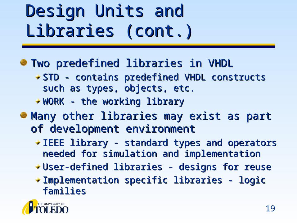
Design Units and Libraries (cont.)Design Units and Libraries (cont.)
Two predefined libraries in VHDLTwo predefined libraries in VHDLSTD - contains predefined VHDL constructs such as types, STD - contains predefined VHDL constructs such as types, objects, etc.objects, etc.
WORK - the working libraryWORK - the working library
Many other libraries may exist as part of development Many other libraries may exist as part of development environmentenvironment
IEEE library - standard types and operators needed for IEEE library - standard types and operators needed for simulation and implementation simulation and implementation
User-defined libraries - designs for reuseUser-defined libraries - designs for reuse
Implementation specific libraries - logic familiesImplementation specific libraries - logic families

Modeling Latches and Flip-FlopsModeling Latches and Flip-Flops
21
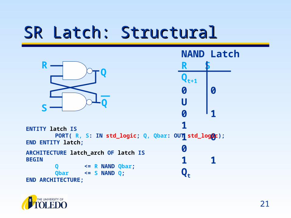
SR Latch: StructuralSR Latch: StructuralNAND LatchR S Qt+1
0 0 U0 1 11 0 01 1 Qt
R
S
Q
Q
ENTITY latch ISPORT( R, S: IN std_logic; Q, Qbar: OUT std_logic);
END ENTITY latch;
ARCHITECTURE latch_arch OF latch ISBEGIN
Q <= R NAND Qbar;Qbar <= S NAND Q;
END ARCHITECTURE;
22
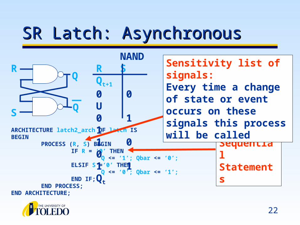
SR Latch: Asynchronous SR Latch: Asynchronous
ARCHITECTURE latch2_arch OF latch ISBEGIN
PROCESS (R, S) BEGINIF R = ‘0’ THEN
Q <= ‘1’; Qbar <= ‘0’;ELSIF S =‘0’ THEN
Q <= ‘0’; Qbar <= ‘1’;END IF;
END PROCESS;END ARCHITECTURE;
NANDR S Qt+1
0 0 U0 1 11 0 01 1 Qt
R
S
Q
Q
SequentialStatements
Sensitivity list of signals:Every time a change of state or event occurs on these signals this process will be called
23
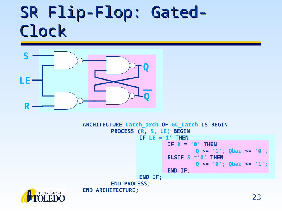
SR Flip-Flop: Gated-ClockSR Flip-Flop: Gated-Clock
S
R
Q
Q
LE
ARCHITECTURE Latch_arch OF GC_Latch IS BEGINPROCESS (R, S, LE) BEGIN
IF LE =‘1’ THENIF R = ‘0’ THEN
Q <= ‘1’; Qbar <= ‘0’;ELSIF S =‘0’ THEN
Q <= ‘0’; Qbar <= ‘1’;END IF;
END IF;END PROCESS;
END ARCHITECTURE;

24
Data-Flip Flops: SynchronousData-Flip Flops: Synchronous
ARCHITECTURE Dff_arch OF Dff ISBEGIN
PROCESS (Clock) BEGINIF Clock’EVENT AND Clock=‘1’ THEN
Q <= D;END IF;
END PROCESS;
END ARCHITECTURE;Clock’EVENT is what distinguishes a D-FlipFlip from a Latch
Notice the Process does not contain D:PROCESS(Clock, D)
Sensitivity lists contain signals used in conditionals (i.e., IF)
25
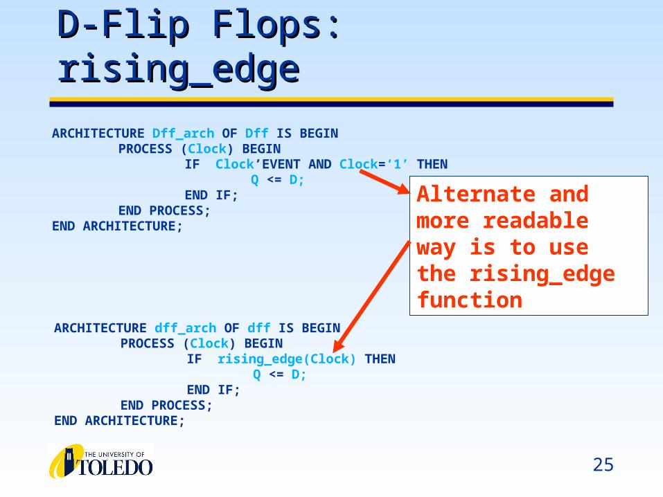
D-Flip Flops: rising_edgeD-Flip Flops: rising_edge
ARCHITECTURE Dff_arch OF Dff IS BEGINPROCESS (Clock) BEGIN
IF Clock’EVENT AND Clock=‘1’ THENQ <= D;
END IF;END PROCESS;
END ARCHITECTURE;
ARCHITECTURE dff_arch OF dff IS BEGINPROCESS (Clock) BEGIN
IF rising_edge(Clock) THENQ <= D;
END IF;END PROCESS;
END ARCHITECTURE;
Alternate andmore readable way is to use the rising_edge function
26
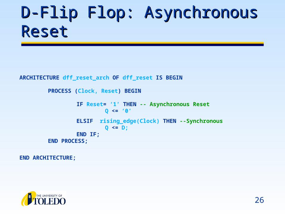
D-Flip Flop: Asynchronous ResetD-Flip Flop: Asynchronous Reset
ARCHITECTURE dff_reset_arch OF dff_reset IS BEGIN
PROCESS (Clock, Reset) BEGIN
IF Reset= ‘1’ THEN -- Asynchronous ResetQ <= ‘0’
ELSIF rising_edge(Clock) THEN --Synchronous Q <= D;
END IF;END PROCESS;
END ARCHITECTURE;

27
D-Flip Flops: Synchronous ResetD-Flip Flops: Synchronous Reset
PROCESS (Clock, Reset) BEGINIF rising_edge(Clock) THEN
IF Reset=‘1’ THENQ <= ‘0’
ELSEQ <= D;
END IF;END IF;
END PROCESS;
Synchronous Reset
Synchronous FF
PROCESS (Clock, Reset) BEGINIF Reset=‘1’ THEN
Q <= ‘0’ELSIF rising_edge(Clock) THEN
Q <= D;END IF;
END PROCESS;
Asynchronous Reset
Synchronous FF
28
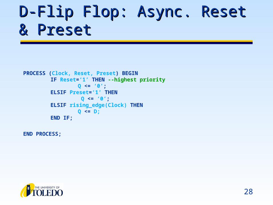
D-Flip Flop: Async. Reset & PresetD-Flip Flop: Async. Reset & Preset
PROCESS (Clock, Reset, Preset) BEGINIF Reset=‘1’ THEN --highest priority
Q <= ‘0’;ELSIF Preset=‘1’ THEN
Q <= ‘0’;ELSIF rising_edge(Clock) THEN
Q <= D;END IF;
END PROCESS;
Vector operations and conditional Vector operations and conditional concurrent signal assignmentsconcurrent signal assignments
30
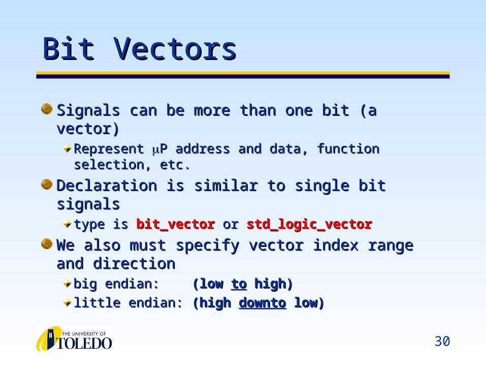
Bit VectorsBit Vectors
Signals can be more than one bit (a vector)Signals can be more than one bit (a vector)Represent Represent P address and data, function selection, etc.P address and data, function selection, etc.
Declaration is similar to single bit signalsDeclaration is similar to single bit signalstype is type is bit_vectorbit_vector or or std_logic_vectorstd_logic_vector
We also must specify vector index range and We also must specify vector index range and directiondirection
big endian: big endian: (low (low toto high) high)
little endian:little endian: (high (high downtodownto low) low)
31
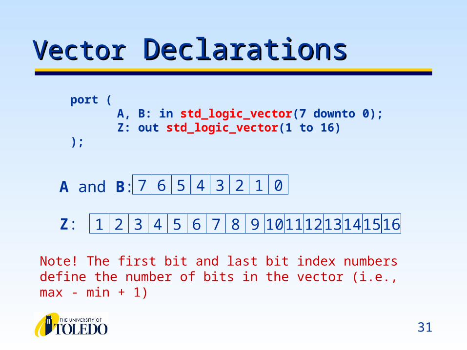
VectorVector Declarations Declarations
port (A, B: in std_logic_vector(7 downto 0);Z: out std_logic_vector(1 to 16)
);
A and B:
Z: 1 2 3 4 5 6 7 8 9
7 6 5 4 3 2 1 0
10 11 12 13 14 15 16
Note! The first bit and last bit index numbers define the number of bits in the vector (i.e., max - min + 1)
32
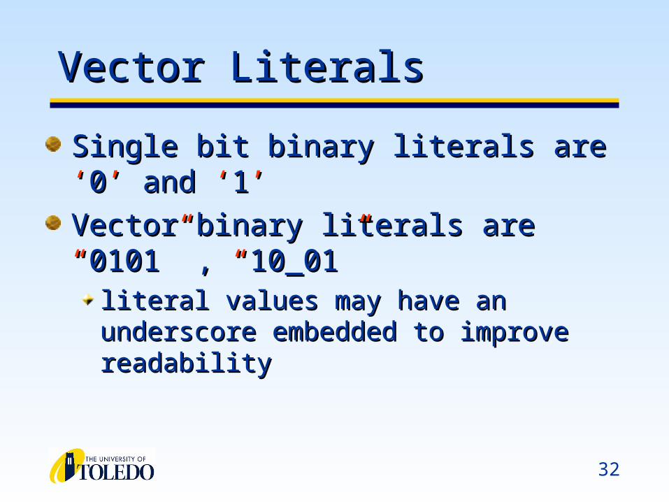
Vector LiteralsVector Literals
Single bit binary literals are Single bit binary literals are ‘‘00’’ and and ‘‘11’’
Vector binary literals are Vector binary literals are ““01010101”” , , ““10_0110_01””
literal values may have an underscore embedded literal values may have an underscore embedded to improve readabilityto improve readability

33
Vector Logical OperationsVector Logical Operations
Single bit logical operations also apply to Single bit logical operations also apply to vectorsvectors
Operands Operands MUSTMUST be the same size (generally be the same size (generally applies to all vector operations)applies to all vector operations)
Assignment target must also have the same Assignment target must also have the same number of bits as the resultnumber of bits as the result
Operations are applied bitwise to operands to Operations are applied bitwise to operands to produce the vector resultproduce the vector result
34
Vector OperationsVector Operations
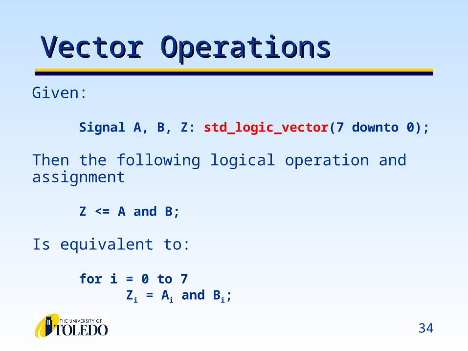
Given:
Signal A, B, Z: std_logic_vector(7 downto 0);
Then the following logical operation and assignment
Z <= A and B;
Is equivalent to:
for i = 0 to 7Zi = Ai and Bi;
35
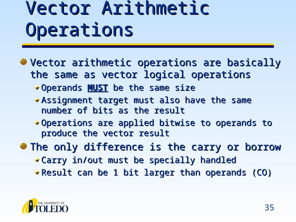
Vector Arithmetic OperationsVector Arithmetic Operations
Vector arithmetic operations are basically the same as Vector arithmetic operations are basically the same as vector logical operationsvector logical operations
Operands Operands MUSTMUST be the same size be the same size
Assignment target must also have the same number of bits as Assignment target must also have the same number of bits as the resultthe result
Operations are applied bitwise to operands to produce the Operations are applied bitwise to operands to produce the vector resultvector result
The only difference is the carry or borrowThe only difference is the carry or borrowCarry in/out must be specially handledCarry in/out must be specially handled
Result can be 1 bit larger than operands (CO)Result can be 1 bit larger than operands (CO)

36
4-bit Adder (Dataflow VHDL)4-bit Adder (Dataflow VHDL)
entity add4 isport (a, b: in std_logic_vector (3 downto 0);
cin: in std_logic; cout: out std_logic;s: out std_logic_vector(3 downto 0)
);end add4;
architecture df of add4 issignal tmpsum std_logic_vector(4 downto 0);
begintmpsum <= (‘0’ & a) + (‘0’ & b) + (“0000” & cin);s <= tmpsum(3 downto 0);cout <= tmpsum(4);
end df;
37
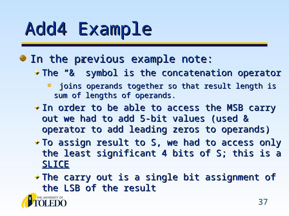
Add4 ExampleAdd4 Example
In the previous example note:In the previous example note:The “&” symbol is the concatenation operatorThe “&” symbol is the concatenation operator
joins operands together so that result length is sum of lengths of joins operands together so that result length is sum of lengths of operands.operands.
In order to be able to access the MSB carry out we had to add In order to be able to access the MSB carry out we had to add 5-bit values (used & operator to add leading zeros to 5-bit values (used & operator to add leading zeros to operands)operands)
To assign result to S, we had to access only the least To assign result to S, we had to access only the least significant 4 bits of S; this is a significant 4 bits of S; this is a SLICESLICE
The carry out is a single bit assignment of the LSB of the The carry out is a single bit assignment of the LSB of the resultresult

38
Vectors and ConcatenationVectors and Concatenation
signal A: std_logic_vector(3 downto 0);signal B: std_logic_vector(3 downto 0);signal C, D, E: std_logic_vector(7 downto 0);
A <= ”0000”; B <= ”1111”; C <= A & B; -- C = ”00001111”
D <= ‘0’ & ”0001111”; -- D <= ”00001111”
E <= ‘0’ & ‘0’ & ‘0’ & ‘0’ & ‘1’ & ‘1’ & ‘1’ & ‘1’; -- E <= ”00001111”
39
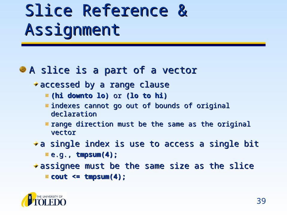
Slice Reference & AssignmentSlice Reference & Assignment
A slice is a part of a vectorA slice is a part of a vector
accessed by a range clauseaccessed by a range clause (hi downto lo)(hi downto lo) or or (lo to hi)(lo to hi)
indexes cannot go out of bounds of original declarationindexes cannot go out of bounds of original declaration
range direction must be the same as the original vectorrange direction must be the same as the original vector
a single index is use to access a single bita single index is use to access a single bite.g., e.g., tmpsum(4);tmpsum(4);
assignee must be the same size as the sliceassignee must be the same size as the slicecout <= tmpsum(4);cout <= tmpsum(4);
40
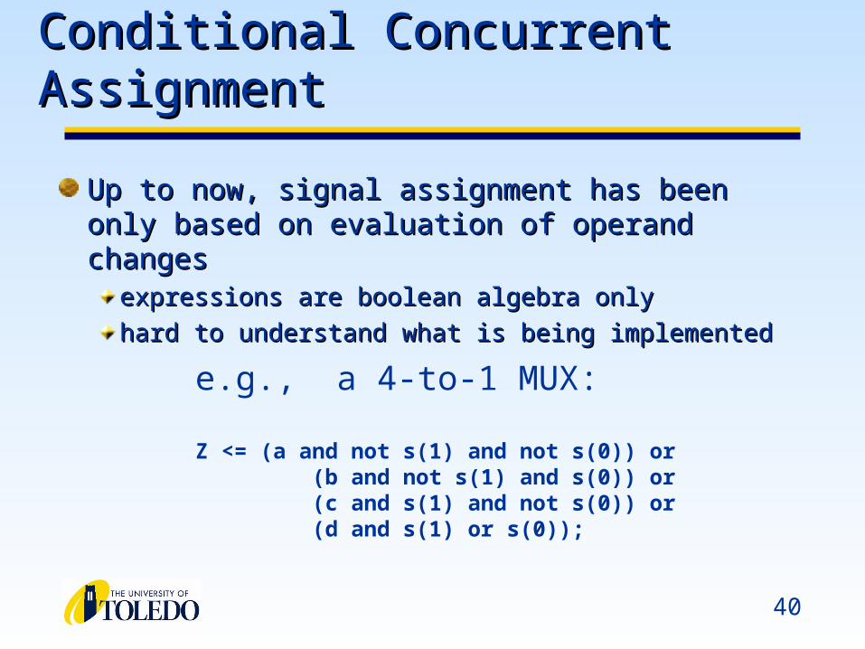
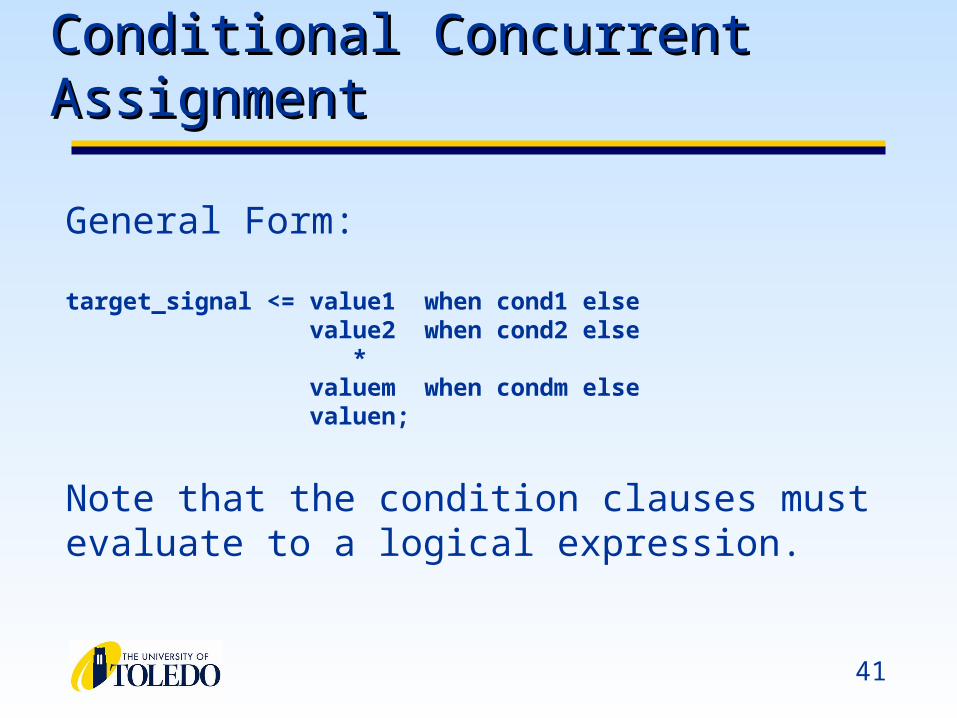
Conditional Concurrent AssignmentConditional Concurrent Assignment
Up to now, signal assignment has been only based Up to now, signal assignment has been only based on evaluation of operand changeson evaluation of operand changes
expressions are boolean algebra onlyexpressions are boolean algebra only
hard to understand what is being implementedhard to understand what is being implemented
e.g., a 4-to-1 MUX:
Z <= (a and not s(1) and not s(0)) or (b and not s(1) and s(0)) or (c and s(1) and not s(0)) or (d and s(1) or s(0));
41
Conditional Concurrent AssignmentConditional Concurrent Assignment
General Form:
target_signal <= value1 when cond1 else value2 when cond2 else
* valuem when condm else valuen;
Note that the condition clauses must evaluate to a logical expression.
42
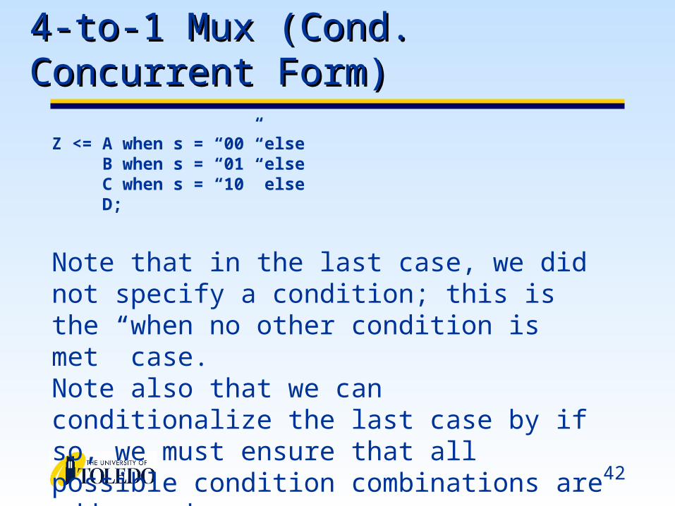
4-to-1 Mux (Cond. Concurrent Form)4-to-1 Mux (Cond. Concurrent Form)
Z <= A when s = “00” else B when s = “01” else C when s = “10” else D;
Note that in the last case, we did not specify a condition; this is the “when no other condition is met” case.Note also that we can conditionalize the last case by if so, we must ensure that all possible condition combinations are addressed.
43
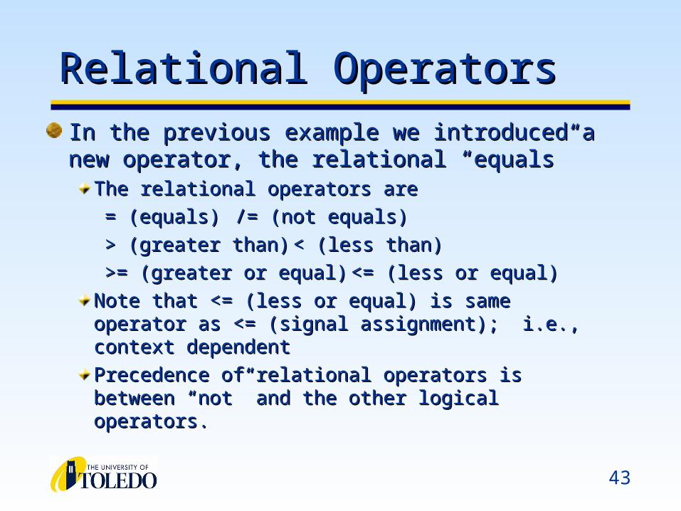
Relational OperatorsRelational Operators
In the previous example we introduced a new In the previous example we introduced a new operator, the relational “equals”operator, the relational “equals”
The relational operators areThe relational operators are
= (equals)= (equals) /= (not equals)/= (not equals)
> (greater than)> (greater than) < (less than)< (less than)
>= (greater or equal)>= (greater or equal) <= (less or equal)<= (less or equal)
Note that <= (less or equal) is same operator as <= Note that <= (less or equal) is same operator as <= (signal assignment); i.e., context dependent(signal assignment); i.e., context dependent
Precedence of relational operators is between “not” and Precedence of relational operators is between “not” and the other logical operators.the other logical operators.
44
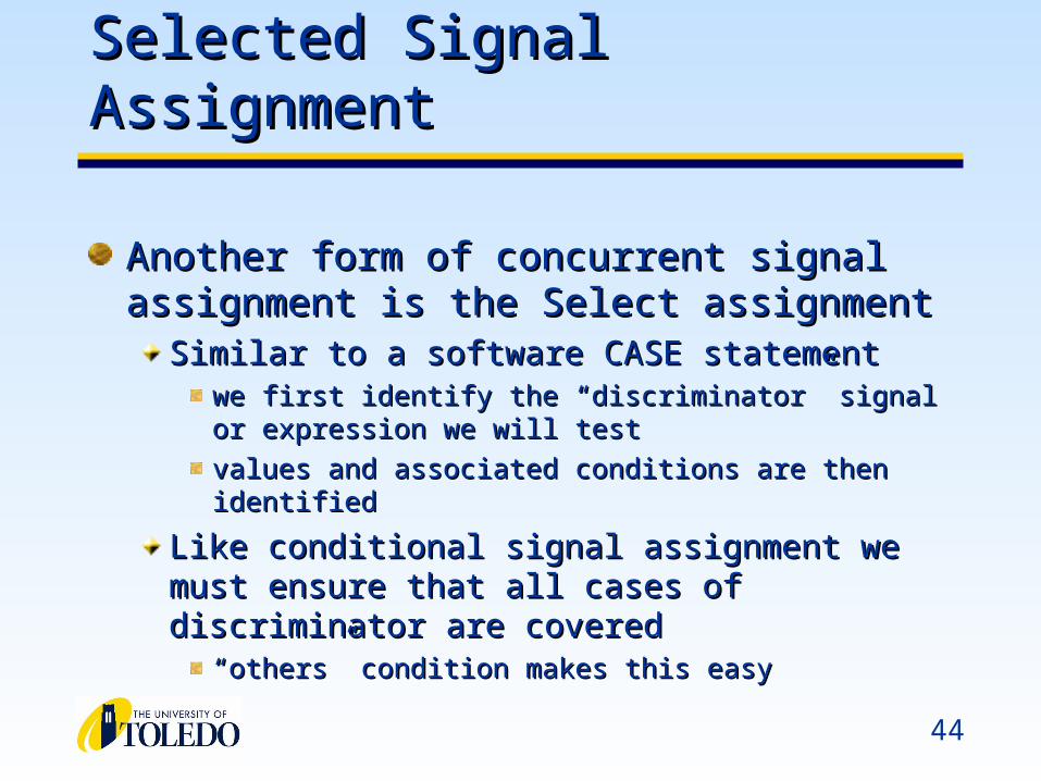
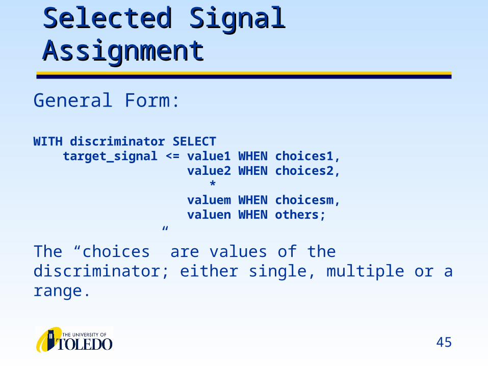
Selected Signal Assignment Selected Signal Assignment
Another form of concurrent signal assignment is Another form of concurrent signal assignment is the Select assignmentthe Select assignment
Similar to a software CASE statementSimilar to a software CASE statementwe first identify the “discriminator” signal or expression we we first identify the “discriminator” signal or expression we will testwill test
values and associated conditions are then identifiedvalues and associated conditions are then identified
Like conditional signal assignment we must ensure that Like conditional signal assignment we must ensure that all cases of discriminator are coveredall cases of discriminator are covered
““others” condition makes this easyothers” condition makes this easy
45
Selected Signal AssignmentSelected Signal Assignment
General Form:
WITH discriminator SELECT target_signal <= value1 WHEN choices1, value2 WHEN choices2,
* valuem WHEN choicesm, valuen WHEN others;
The “choices” are values of the discriminator; either single, multiple or a range.
46
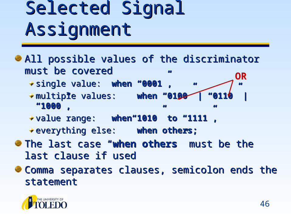
Selected Signal AssignmentSelected Signal Assignment
All possible values of the discriminator must be coveredAll possible values of the discriminator must be coveredsingle value:single value: when “0001”,when “0001”,
multiple values:multiple values: when “0100” | “0110” | when “0100” | “0110” | “1000”,“1000”,
value range:value range: when“1010” to “1111”,when“1010” to “1111”,
everything else:everything else: when others;when others;
The last case “The last case “when otherswhen others” must be the last clause if ” must be the last clause if usedused
Comma separates clauses, semicolon ends the statementComma separates clauses, semicolon ends the statement
OR

47
Selected Signal AssignmentSelected Signal Assignment
WITH digit SELECTsegs <= “1110111” when “0000”,
“0010010” when “0001”, “1011101” when “0010”, “1011011” when “0011”, “0111010” when “0100”, “1101011” when “0101”, “0101111” when “0110”, “1010010” when “0111”, “1111111” when “1000”, “1111010” when “1001”, “1101101” when others;
48
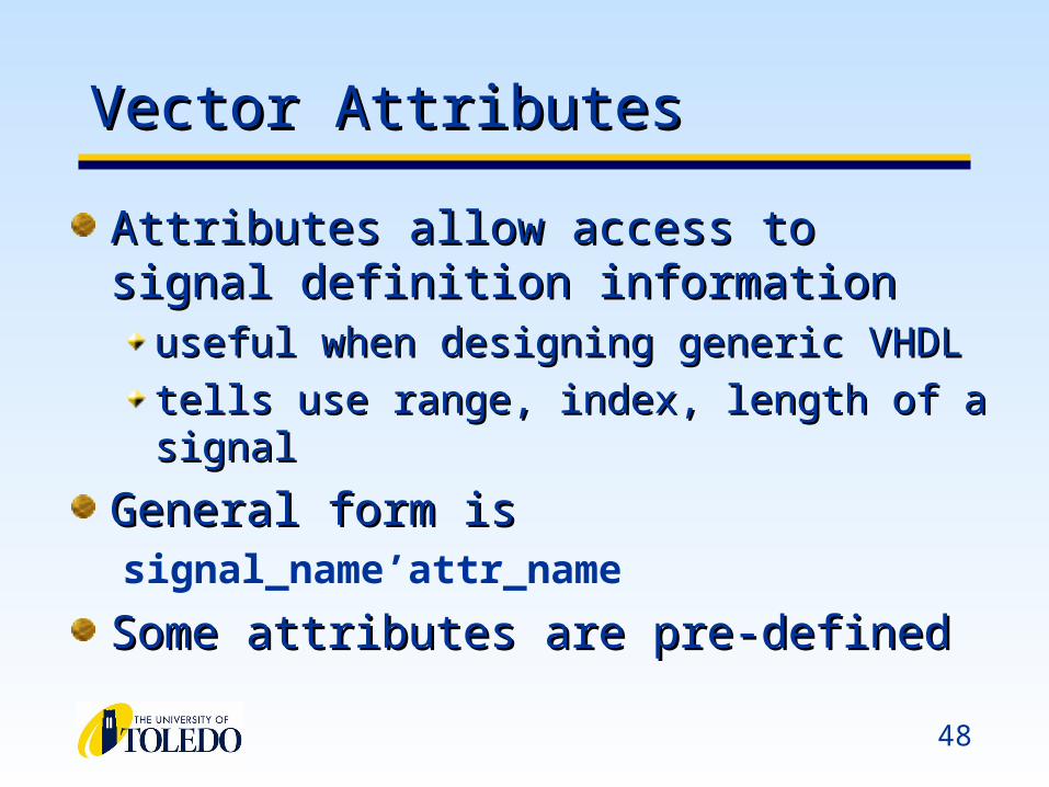
Vector AttributesVector Attributes
Attributes allow access to signal definition Attributes allow access to signal definition informationinformation
useful when designing generic VHDL useful when designing generic VHDL
tells use range, index, length of a signaltells use range, index, length of a signal
General form isGeneral form issignal_name’attr_name
Some attributes are pre-definedSome attributes are pre-defined
49
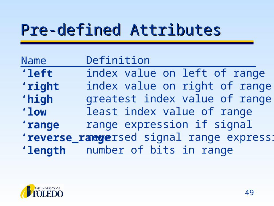
Pre-defined AttributesPre-defined Attributes
Name‘left‘right‘high‘low‘range‘reverse_range‘length
Definitionindex value on left of rangeindex value on right of rangegreatest index value of rangeleast index value of rangerange expression if signalreversed signal range expressionnumber of bits in range
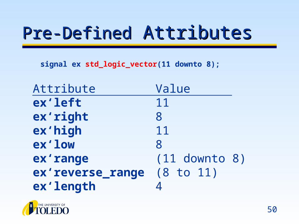
50
Pre-DefinedPre-Defined Attributes Attributes
Attributeex‘leftex‘rightex‘highex‘lowex‘rangeex‘reverse_rangeex‘length
Value118118(11 downto 8)(8 to 11)4
signal ex std_logic_vector(11 downto 8);

Latches, Flip-Flops and RegistersLatches, Flip-Flops and Registers
52
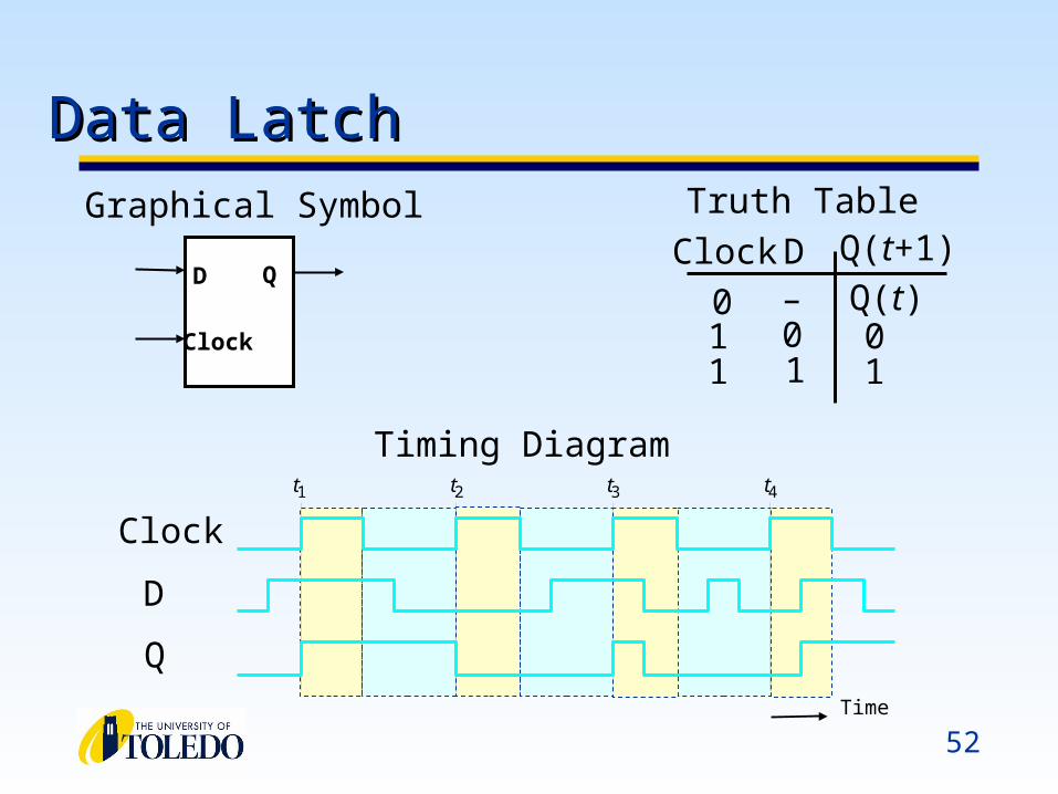
Clock D 0 1 1
– 0 1
0 1
Truth Table Graphical Symbol
t 1 t 2 t 3 t 4
Time
Clock
D
Q
Timing Diagram
Q(t+1)
Q(t)
Data LatchData Latch
D Q
Clock
53
LIBRARY ieee ; USE ieee.std_logic_1164.all ;
ENTITY latch IS PORT ( D, Clock : IN STD_LOGIC;
Q : OUT STD_LOGIC); END latch;
ARCHITECTURE Behavior OF latch IS BEGIN
PROCESS ( D, Clock ) BEGIN
IF Clock = '1' THEN Q <= D;
END IF; END PROCESS;
END Behavior;
Data LatchData Latch
D Q
Clock
54
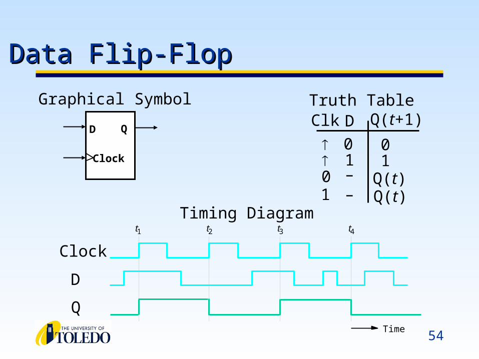
Clk D
0 1
0 1
Truth Table
t 1 t 2 t 3 t 4
Time
Clock
D
Q
Timing Diagram
Q(t+1)
Q(t)
Data Flip-FlopData Flip-Flop
D Q
Clock
Graphical Symbol
0 – Q(t)1 –
55
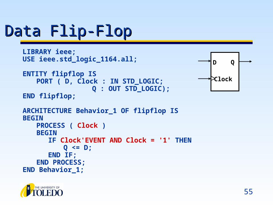
LIBRARY ieee; USE ieee.std_logic_1164.all;
ENTITY flipflop IS PORT ( D, Clock : IN STD_LOGIC;
Q : OUT STD_LOGIC); END flipflop;
ARCHITECTURE Behavior_1 OF flipflop IS BEGIN
PROCESS ( Clock ) BEGIN
IF Clock'EVENT AND Clock = '1' THEN Q <= D;
END IF; END PROCESS;
END Behavior_1;
Data Flip-FlopData Flip-Flop
D Q
Clock
56
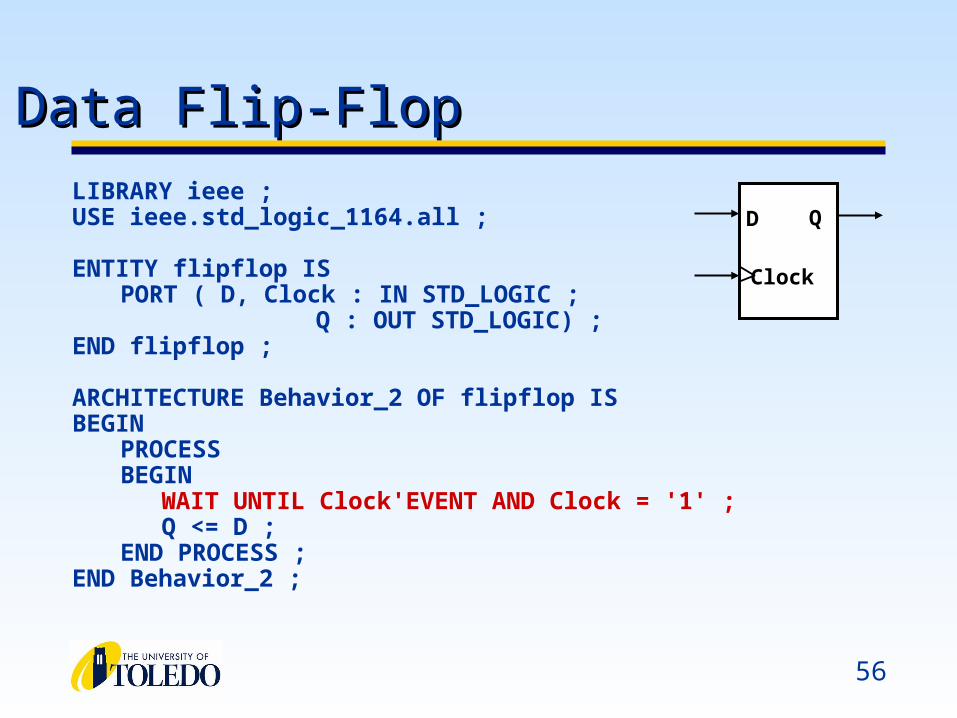
LIBRARY ieee ; USE ieee.std_logic_1164.all ;
ENTITY flipflop IS PORT ( D, Clock : IN STD_LOGIC ;
Q : OUT STD_LOGIC) ; END flipflop ;
ARCHITECTURE Behavior_2 OF flipflop IS BEGIN
PROCESSBEGIN
WAIT UNTIL Clock'EVENT AND Clock = '1' ; Q <= D ;
END PROCESS ; END Behavior_2 ;
Data Flip-FlopData Flip-Flop
D Q
Clock
57
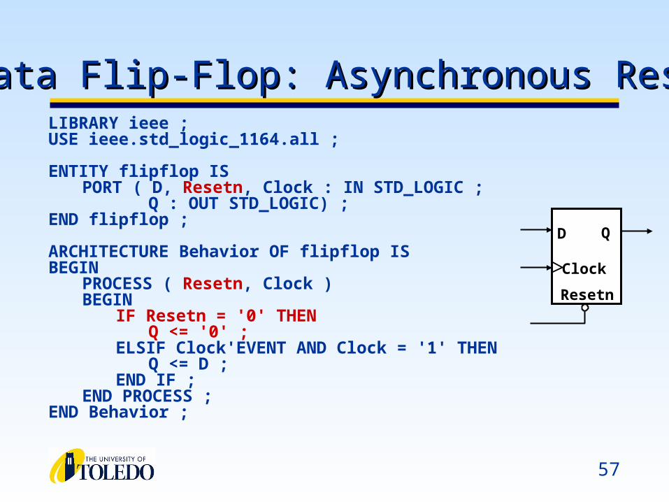
LIBRARY ieee ; USE ieee.std_logic_1164.all ;
ENTITY flipflop IS PORT ( D, Resetn, Clock : IN STD_LOGIC ;
Q : OUT STD_LOGIC) ; END flipflop ;
ARCHITECTURE Behavior OF flipflop IS BEGIN
PROCESS ( Resetn, Clock ) BEGIN
IF Resetn = '0' THEN Q <= '0' ;
ELSIF Clock'EVENT AND Clock = '1' THEN Q <= D ;
END IF ; END PROCESS ;
END Behavior ;
Data Flip-Flop: Asynchronous ResetData Flip-Flop: Asynchronous Reset
D Q
Clock
Resetn
58
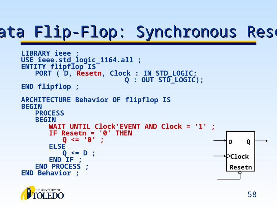
LIBRARY ieee ; USE ieee.std_logic_1164.all ; ENTITY flipflop IS
PORT ( D, Resetn, Clock : IN STD_LOGIC; Q : OUT STD_LOGIC);
END flipflop ;
ARCHITECTURE Behavior OF flipflop IS BEGIN
PROCESS BEGIN
WAIT UNTIL Clock'EVENT AND Clock = '1' ; IF Resetn = '0' THEN
Q <= '0' ; ELSE
Q <= D ; END IF ;
END PROCESS ;END Behavior ;
Data Flip-Flop: Synchronous ResetData Flip-Flop: Synchronous Reset
D Q
Clock
Resetn
59
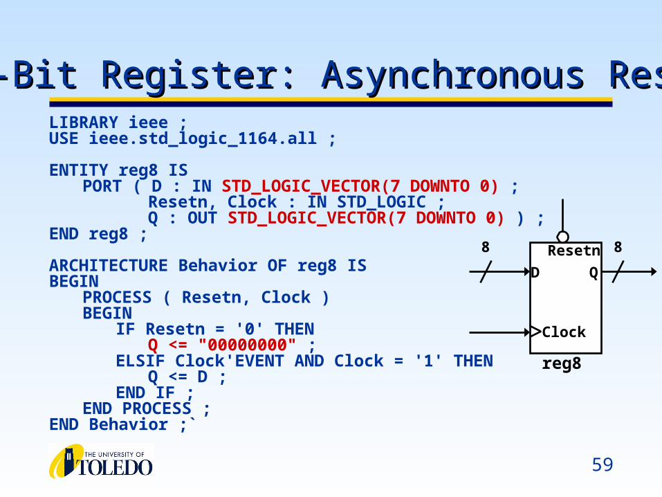
8-Bit Register: Asynchronous Reset8-Bit Register: Asynchronous ResetLIBRARY ieee ;USE ieee.std_logic_1164.all ;
ENTITY reg8 ISPORT ( D : IN STD_LOGIC_VECTOR(7 DOWNTO 0) ;
Resetn, Clock : IN STD_LOGIC ;Q : OUT STD_LOGIC_VECTOR(7 DOWNTO 0) ) ;
END reg8 ;
ARCHITECTURE Behavior OF reg8 ISBEGIN
PROCESS ( Resetn, Clock )BEGIN
IF Resetn = '0' THENQ <= "00000000" ;
ELSIF Clock'EVENT AND Clock = '1' THENQ <= D ;
END IF ;END PROCESS ;
END Behavior ;`
Resetn
Clock
reg8
8 8
D Q
60
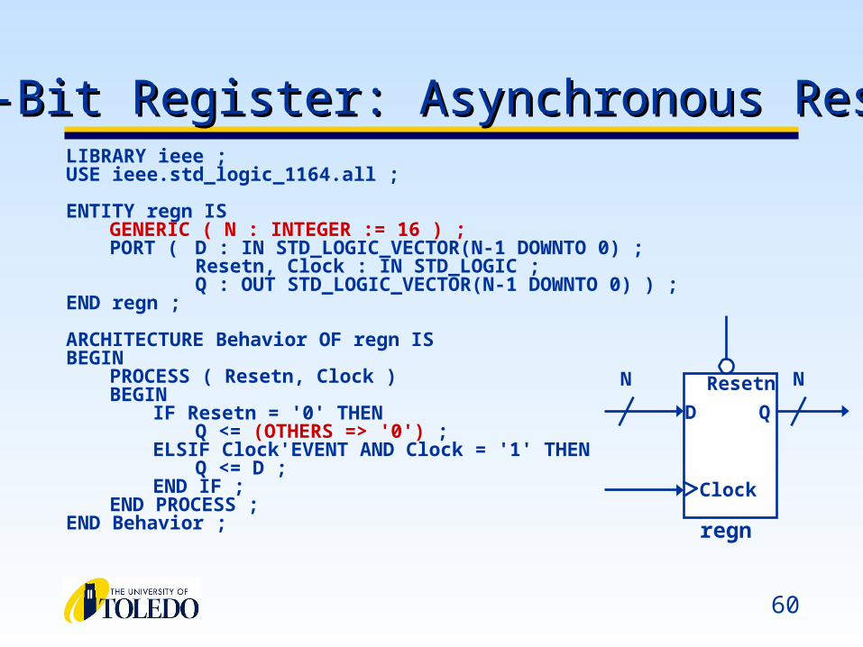
N-Bit Register: Asynchronous ResetN-Bit Register: Asynchronous ResetLIBRARY ieee ;USE ieee.std_logic_1164.all ;
ENTITY regn ISGENERIC ( N : INTEGER := 16 ) ;PORT ( D : IN STD_LOGIC_VECTOR(N-1 DOWNTO 0) ;
Resetn, Clock : IN STD_LOGIC ;Q : OUT STD_LOGIC_VECTOR(N-1 DOWNTO 0) ) ;
END regn ;
ARCHITECTURE Behavior OF regn ISBEGIN
PROCESS ( Resetn, Clock )BEGIN
IF Resetn = '0' THENQ <= (OTHERS => '0') ;
ELSIF Clock'EVENT AND Clock = '1' THENQ <= D ;
END IF ;END PROCESS ;
END Behavior ;
Resetn
Clock
regn
N N
D Q
61
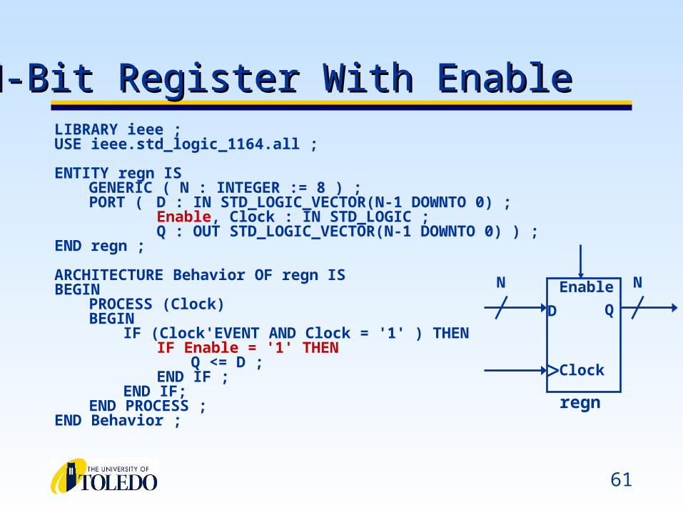
LIBRARY ieee ;USE ieee.std_logic_1164.all ;
ENTITY regn ISGENERIC ( N : INTEGER := 8 ) ;PORT ( D : IN STD_LOGIC_VECTOR(N-1 DOWNTO 0) ;
Enable, Clock : IN STD_LOGIC ;Q : OUT STD_LOGIC_VECTOR(N-1 DOWNTO 0) ) ;
END regn ;
ARCHITECTURE Behavior OF regn ISBEGIN
PROCESS (Clock)BEGIN
IF (Clock'EVENT AND Clock = '1' ) THENIF Enable = '1' THEN
Q <= D ;END IF ;
END IF;END PROCESS ;
END Behavior ;
N-Bit Register With EnableN-Bit Register With Enable
QD
Enable
Clock
regn
N N