![Cse-IV-graph Theory and Combinatorics [10cs42]-Notes](https://static.fdocuments.us/doc/165x107/563db9de550346aa9aa0a90a/cse-iv-graph-theory-and-combinatorics-10cs42-notes.jpg)
Cse-ct and St Lab (IV-i)
78
MALLA REDDY COLLEGE OF ENGINEERING & TECHNOLOGY DEPARTMENT OF COMPUTER SCIENCE & ENGINEERING CASE TOOLS AND SOFTWARE TESTING Lab Manual For the Academic Year 2013- 2014 IV B Tech Semester -I
-
Upload
umamageswari-kumaresan -
Category
Documents
-
view
9 -
download
0
description
case tools
Transcript of Cse-ct and St Lab (IV-i)

MALLA REDDY COLLEGE OF ENGINEERING & TECHNOLOGY
DEPARTMENT OF COMPUTER SCIENCE & ENGINEERING
CASE TOOLS AND SOFTWARE TESTING Lab Manual
For the Academic Year 2013-2014
IV B Tech Semester -I
INDEX
S.No. Name Of the Experiment Page
Numbers CASE TOOLS
1 Case Tools Introduction 1
2 UML Introduction 1-7
3 ATM System 7-30
SOFTWARE TESTING
1 Write programs in „C‟ Language to demonstrate the working of the following a.
constructs: i) do...while ii) while….do iii) if…else iv)
switch v) for
31
2
A program written in „C‟ language for Matrix Multiplication fails‖ Introspect the causes for its failure and write down the possible reasons for its failure. 39
3 Take any system (e.g. ATM system) and study its system specifications and report
the various bugs.
43
4 Write the test cases for any known application (e.g. Banking application)
44
5 Create a test plan document for any application (e.g. Library Management
System)
50
6 Experiment: Study of Any Testing Tool (Win Runner) 56
7 Experiment : Study of any web testing tool (e.g. Selenium) 62
8 Experiment: Study of Any Bug Tracking Tool (Bugzilla, Bugbit) 66
9 Experiment: Study of Any Test Management Tool ( Test Director) 73
10 Experiment: Study of any open source testing tool (Test Link) 75

CT and STM lab manual Page 1
CASE Tools
Introduction:
CASE tools known as Computer-aided software engineering tools is a kind of
component-based development which allows its users to rapidly develop information systems.
The main goal of case technology is the automation of the entire information systems
development life cycle process using a set of integrated software tools, such as modeling,
methodology and automatic code generation.
Component based manufacturing has several advantages over custom development. The
main advantages are the availability of high quality, defect free products at low cost and at a
faster time. The prefabricated components are customized as per the requirements of the
customers. The components used are pre-built, ready-tested and add value and differentiation by
rapid customization to the targeted customers. However the products we get from case tools are
only a skeleton of the final product required and a lot of programming must be done by hand to
get a fully finished, good product.
Characteristics of CASE:
Some of the characteristics of case tools that make it better than customized development
are;
It is a graphic oriented tool.
It supports decomposition of process.
Some typical CASE tools are:
Unified Modeling Language
Data modeling tools and Source code generation tools
UNIFIED MODELING LANGUAGE
Introduction
The unified modeling language (UML) is a standard language for writing software blue prints.
The UML is a language for
Visualizing
Specifying
Constructing
Documenting
CT and STM lab manual Page 2
The artifacts of a software system:
UML is a language that provides vocabulary and the rules for combing words in that
vocabulary for the purpose of communication
A modeling language is a language whose vocabulary and rules focus on the concept and
physical representation of a system. Vocabulary and rules of a language tell us how to create and
real well formed models, but they don‟t tell you what model you should create and when should
create them.
Visualizing
The UML is more than just a bunch of graphical symbols. In UML each symbol has well defined
semantics. In this manner one developer can write a model in the UML and another developer
or even another tools can interpret the model unambiguously.
Specifying
UML is used fro specifying means building models that are precise, unambiguous and complete.
UML addresses the specification of all the important analysis, design and implementation
decisions that must be made in developing and deploying a software intensive system.
Constructing
UML is not a visual programming language but its models can be directly connected to a variety
of programming languages. This means that it is possible to map from a model in the UML to a
programming language such as java, c++ or VisualBasic or even to tables in a relational database
or the persistent store of an object-oriented database. This mapping permits forward engineering.
The generation of code from a UML model into a programming language. The reverse
engineering is also possible you can reconstruct a model from an implementation
back into the UML.
Documenting
UML is a language for Documenting. A software organization produces all sorts of artifacts in
addition to raw executable code. These artifacts include Requirements, Architecture, Design,
Source code, Project plans ,Test, Prototype, Release. Such artifacts are not only the deliverables
CT and STM lab manual Page 3
of a project, they are also critical in controlling, measuring and communicating about a system
during its development and after its deployment.
Conceptual model of the UML:
To understand the UML, we need to form a conceptual model of the language and this requires
learning three major elements.
The UML Basic Building Blocks.
The Rules that direct how those building blocks may be put together. Some common
mechanisms that apply throughout the UML. As UML describes the real time systems it is very
important to make a conceptual model and then proceed gradually. Conceptual model of UML
can be mastered by learning the following three major elements:
UML building blocks
Rules to connect the building blocks
Common mechanisms of UML
UML building blocks. The building blocks of UML can be defined as:
Things
Relationships
Diagrams
Things:
Things are the most important building blocks of UML. Things can be:
Structural
Behavioral
Grouping
Annotational
Structural things:

CT and STM lab manual Page 4
The Structural things define the static part of the model. They represent physical a
conceptual elements. Following are the brief descriptions of the structural things.
Class:
Class represents set of objects having similar responsibilities.
Interface:
Interface defines a set of operations which specify the responsibility of a class
Use case:
Use case represents a set of actions performed by a system for a specific goal.
Component:
Component describes physical part of a system.
Node: A node can be defined as a physical element that exists at run time.
Behavioral things:
A behavioral thing consists of the dynamic parts of UML models. Following are the behavioral
things:
Interaction:
Interaction is defined as a behavior that consists of a group of messages exchanged among
elements to accomplish a specific task.
State machine:
State machine is useful when the state of an object in its life cycle is important. It defines the
sequence of states an object goes through in response to events. Events are external factors
responsible for state change.
Grouping things
CT and STM lab manual Page 5
Grouping things can be defined as a mechanism to group elements of a UML model together.
There is only one grouping thing available.
Package: Package is the only one grouping thing available for gathering structural and
behavioral things.
Annotational things: Annotational things can be defined as a mechanism to capture remarks,
descriptions, and comments of UML model elements. Note is the only one Annotational thing
available.
Note: A note is used to render comments, constraints etc of an UML element.
Relationships In UML:
Relationship is another most important building block of UML. It shows how elements are
associated with each other and this association describes the functionality of an application.
There are four kinds of relationships available.
Dependency:
Dependency is a relationship between two things in which change in one element also affects the
other one.
Association:
Association is basically a set of links that connects elements of an UML model. It also describes
how many objects are taking part in that relationship.
Generalization:
Generalization can be defined as a relationship which connects a specialized element with a
generalized element. It basically describes inheritance relationship in the world of objects.
Realization:
Realization can be defined as a relationship in which two elements are connected. One element
describes some responsibility which is not implemented and the other one implements them. This
relationship exists in case of interfaces.
CT and STM lab manual Page 6
UML Diagrams:
UML diagrams are the ultimate output of the entire discussion. All the elements, relationships
are used to make a complete UML diagram and the diagram represents asystem. The visual
effect of the UML diagram is the most important part of the entire process. All the other
elements are used to make it a complete one.
UML includes the following nine diagrams and the details are described in the following
Class diagram
Object diagram
Use case diagram
Sequence diagram
Collaboration diagram
Activity diagram
Statechart diagram
Deployment diagram
Component diagram
ARCHITECTURE OF UML
Any real world system is used by different users. The users can be developers, testers, business
people, analysts and many more. So before designing a system the architecture is made with
different perspectives in mind. The most important part is to visualize the system from different
viewer‟s perspective. The better we understand the better we make the system. UML plays an
important role in defining different perspectives of a system. These perspectives are:
Design
Implementation
Process
Deployment
And the centre is the Use Case view which connects all these four. A Use case represents the
functionality of the system. So the other perspectives are connected with use case.

CT and STM lab manual Page 7
Design of a system consists of classes, interfaces and collaboration. UML provides class
diagram, object diagram to support this. Implementation defines the components assembled
together to make a complete physical system. UML component diagram is used to support
implementation perspective.
Process defines the flow of the system. So the same elements as used in Design are also used to
support this perspective.
Deployment represents the physical nodes of the system that forms the hardware. UML
deployment diagram is used to support this perspective.
Automatic Teller Machine
Description of ATM System
The software to be designed will control a simulated automated teller machine (ATM) having a
magnetic stripe reader for reading an ATM card, a customer console (keyboard and display) for
interaction with the customer, a slot for depositing envelopes, a dispenser for cash , a printer for
printing customer receipts, and a key-operated switch to allow an operator to start or stop the
machine. The ATM will communicate with the bank‟s computer over an appropriate
communication link. (The software on the latter is not part of the requirements for this problem.)
The ATM will service one customer at a time. A customer will be required to insert an ATM
card and enter a personal identification number (PIN) – both of which will be sent to the bank for
validation as part of each transaction. The customer will then be able to perform one or more
transactions. The card will be retained in the machine until the customer indicates that he/she
desires no further transactions, at which point it will be returned – except as noted below.
The ATM must be able to provide the following services to the customer:
1. A customer must be able to make a cash withdrawal from any suitable account linked to
the card. Approval must be obtained from the bank before cash is dispensed.
2. A customer must be able to make a deposit to any account linked to the card, consisting
of cash and/or checks in an envelope. The customer will enter the amount of the deposit
into the ATM, subject to manual verification when the envelope is removed from the

CT and STM lab manual Page 8
machine by an operator. Approval must be obtained from the bank before physically
accepting the envelope.
3. A customer must be able to make a transfer of money between any two accounts linked to
the card.
4. A customer must be able to make a balance inquiry of any account linked to the card.
5. A customer must be able to abort a transaction in progress by pressing the Cancel key
instead of responding to a request from the machine.
The ATM will communicate each transaction to the bank and obtain verification that it was
allowed by the bank. Ordinarily, a transaction will be considered complete by the bank once it
has been approved. In the case of a deposit, a second message will be sent to the bank indicating
that the customer has deposited the envelope. (If the customer fails to deposit the envelope
within the timeout period, or presses cancel instead, no second message will be sent to the bank
and the deposit will not be credited to the customer.)
If the bank determines that the customer‟s PIN is invalid, the customer will be required to re-
enter the PIN before a transaction can proceed. If the customer is unable to successfully enter the
PIN after three tries, the card will be permanently retained by the machine, and the customer will
have to contact the bank to get it back.
If a transaction fails for any reason other than an invalid PIN, the ATM will display an
explanation of the problem, and will then ask the customer whether he/she wants to do another
transaction.
The ATM will provide the customer with a printed receipt for each successful transaction,
showing the date, time, machine location, type of transaction, account(s), amount, and ending
and available balance(s) of the affected account (“to” account for transfers).
The ATM will have a key-operated switch that will allow an operator to start and stop the
servicing of customers. After turning the switch to the “on” position, the operator will be
required to verify and enter the total cash on hand. The machine can only be turned off when it is
not servicing a customer. When the switch is moved to the “off” position, the machine will shut
down, so that the operator may remove deposit envelopes and reload the machine with cash,
blank receipts, etc.

CT and STM lab manual Page 9
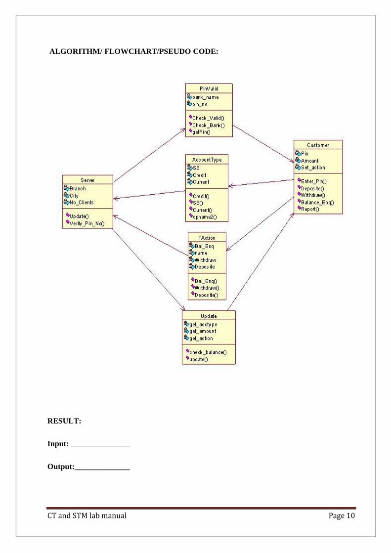
EXPERIMENT : 1
Name of the experiment: Class diagram for ATM System
1.AIM: To design and implement class diagram for ATM system
2.THEORY :
The class diagram is a static diagram. It represents the static view of an application. Class
diagram is not only used for visualizing, describing and documenting different aspects of a
system but also for constructing executable code of the software application. The class diagram
describes the attributes and operations of a class and also the constraints imposed on the system.
The class diagram shows a collection of classes, interfaces, associations, collaborations and
constraints. It is also known as a structural diagram.
Purpose:
The purpose of the class diagram is to model the static view of an application. The class
diagrams are the only diagrams which can be directly mapped with object oriented languages and
thus widely used at the time of construction. The UML diagrams like activity diagram, sequence
diagram can only give the sequence flow of the application but class diagram is a bit different.
So it is the most popular UML diagram in the coder community. So the purpose of the class
diagram can be summarized as:
Analysis and design of the static view of an application.
Describe responsibilities of a system.
Base for component and deployment diagrams.
Forward and reverse engineering.
Contents:
Class diagrams commonly contain the following things
Classes
Interfaces
Collaborations
Dependency, generalization and association relationships
CT and STM lab manual Page 10
ALGORITHM/ FLOWCHART/PSEUDO CODE:
RESULT:
Input: _______________
Output:______________
CT and STM lab manual Page 11
Inferences:
1. understand the concept of classes
2. identify classes and attributes and operations for a class
3. model the class diagram for the system
sample input:
Class: Book
Book
Applications:
Online transaction
Online banking
Questions
CT and STM lab manual Page 12
EXPERIMENT : 2
NAME OF EXPERIMENT: Use case diagram for ATM System.
AIM: To design and implement Use case diagram for ATM System.
THEORY: A Use case Diagram is a diagram that shows a set of Use cases and actors and
their relationships.These diagrams are used to model the static use case view of a system.
To model a system the most important aspect is to capture the dynamic behaviour. To clarify a
bit in details, dynamic behaviour means the behaviour of the system when it is running
/operating. So only static behaviour is not sufficient to model a system rather dynamic behaviour
is more important than static behaviour. In UML there are five diagrams available to model
dynamic nature and use case diagram is one of them. Now as we have to discuss that the use case
diagram is dynamic in nature there should be some internal or external factors for making the
interaction.These internal and external agents are known as actors. So use case diagrams are
consists of actors, use cases and their relationships. The diagram is used to model the
system/subsystem ofan application. A single use case diagram captures a particular functionality
of a system. So to model the entire system numbers of use case diagrams are used.
Purpose:
The purpose of use case diagram is to capture the dynamic aspect of a system. But this definition
is too generic to describe the purpose. Because other four diagrams (activity, sequence,
collaboration and Statechart) are also having the same purpose. So we will look into some
specific purpose which will distinguish it from other four diagrams. Use case diagrams are used
to gather the requirements of a system including internal and external influences. These
requirements are mostly design requirements. So when a system is analyzed to gather its
functionalities use cases are prepared and actors are identified.
So in brief, the purposes of use case diagrams can be as follows:

CT and STM lab manual Page 13
Used to gather requirements of a system.
Used to get an outside view of a system.
Identify external and internal factors influencing the system.
Show the interacting among the requirements are actors.
ALGORITHM/ FLOWCHART/PSEUDO CODE:
RESULT:
user
Enter pin
Withdraw
Deposit
Balance enquiry
atm
admin1 check
cancel
CT and STM lab manual Page 14
Input: _______________
Output:______________
Inferences:
1.Identification of use cases.
2. Identification of actors.
Sample input:
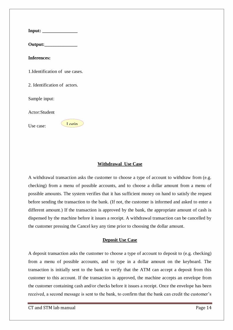
Actor:Student
Use case:
Withdrawal Use Case
A withdrawal transaction asks the customer to choose a type of account to withdraw from (e.g.
checking) from a menu of possible accounts, and to choose a dollar amount from a menu of
possible amounts. The system verifies that it has sufficient money on hand to satisfy the request
before sending the transaction to the bank. (If not, the customer is informed and asked to enter a
different amount.) If the transaction is approved by the bank, the appropriate amount of cash is
dispensed by the machine before it issues a receipt. A withdrawal transaction can be cancelled by
the customer pressing the Cancel key any time prior to choosing the dollar amount.
Deposit Use Case
A deposit transaction asks the customer to choose a type of account to deposit to (e.g. checking)
from a menu of possible accounts, and to type in a dollar amount on the keyboard. The
transaction is initially sent to the bank to verify that the ATM can accept a deposit from this
customer to this account. If the transaction is approved, the machine accepts an envelope from
the customer containing cash and/or checks before it issues a receipt. Once the envelope has been
received, a second message is sent to the bank, to confirm that the bank can credit the customer‟s
Login

CT and STM lab manual Page 15
account – contingent on manual verification of the deposit envelope contents by an operator
later.
A deposit transaction can be cancelled by the customer pressing the Cancel key any time prior to
inserting the envelope containing the deposit. The transaction is automatically cancelled if the
customer fails to insert the envelope containing the deposit within a reasonable period of time
after being asked to do so.
Transfer UseCase
A transfer transaction asks the customer to choose a type of account to transfer from (e.g.
checking) from a menu of possible accounts, to choose a different account to transfer to, and to
type in a dollar amount on the keyboard. No further action is required once the transaction is
approved by the bank before printing the receipt.
A transfer transaction can be cancelled by the customer pressing the Cancel key any time prior to
entering a dollar amount.
Inquiry Use Case
An inquiry transaction asks the customer to choose a type of account to inquire about from a
menu of possible accounts. No further action is required once the transaction is approved by the
bank before printing the receipt. An inquiry transaction can be cancelled by the customer
pressing the Cancel key any time prior to choosing the account to inquire about.
ValidateUser usecase:
This usecase is for validate the user i.e check the pin number, when the bank reports that the
customer‟s transaction is disapproved due to an invalid PIN. The customer is required to re-enter
the PIN and the original request is sent to the bank again. If the bank now approves the
transaction, or disapproves it for some other reason, the original use case is continued; otherwise
the process of re-entering the PIN is repeated. Once the PIN is successfully re-entered
If the customer fails three times to enter the correct PIN, the card is permanently retained, a
screen is displayed informing the customer of this and suggesting he/she contact the bank, and
the entire customer session is aborted.

CT and STM lab manual Page 16
PrintBill usecase
This usecase is for printing corresponding bill after transactions(withdraw or deposit ,or balance
enquiry, transfer) are completed.
Update Account
This usecase is for updating corresponding user accounts after transactions (withdraw or deposit
or transfer) are completed.
Questions:
3. INTERACTION DIAGRAMS
We have two types of interaction diagrams in UML. One is sequence diagram and the other is a
collaboration diagram. The sequence diagram captures the time sequence of message flow from
one object to another and the collaboration diagram describes the organization of objects in a
system taking part in the message flow.
So the following things are to identified clearly before drawing the interaction diagram:
1. Objects taking part in the interaction.
2. Message flows among the objects.
3. The sequence in which the messages are flowing.
4. Object organization.
Purpose:
1. To capture dynamic behaviour of a system.
2. To describe the message flow in the system.
3. To describe structural organization of the objects.
4. To describe interaction among objects.
Contents of a Sequence Diagram
Objects
Focus of control

CT and STM lab manual Page 17
Messages
Life line
Contents.
Contents of a Collaboration Diagram
Objects
Links
Messages

CT and STM lab manual Page 18
EXPERIMENT : 3
Name of the experiment: Sequence diagram for ATM System
AIM: To design and implement Sequence diagram for ATM System.
THEORY: A Sequence diagram is an interaction diagram that emphasizes the time ordering of
messages. This diagram is used to show the dynamic view of a system.
ALGORITHM/ FLOWCHART/PSEUDO CODE
ATM ADMIN
check pin no
pin valid/invalid
check account
display status
check amount
display status
update account

CT and STM lab manual Page 19
EXPERIMENT : 2
NAME OF EXPERIMENT: Use case diagram for ATM System.
AIM: To design and implement Use case diagram for ATM System.
ALGORITHM/ FLOWCHART/PSEUDO CODE
ATM ADMIN
1: check pin no 3: check account 5: check amount
7: update account
2: pin valid/invalid 4: display status 6: display status

CT and STM lab manual Page 20
5. STATE Diagram
Statechart diagram is used to model dynamic nature of a system. They define different states of
an object during its lifetime. And these states are changed by events. So Statechart diagrams are
useful to model reactive systems. Reactive systems can be defined as a system that responds to
external or internal events.
Statechart diagram describes the flow of control from one state to another state. States are
defined as a condition in which an object exists and it changes when some event is triggered. So
the most important purpose of Statechart diagram is to model life time of an object from creation
to termination.
Statechart diagrams are also used for forward and reverse engineering of a system. But the main
purpose is to model reactive system.
Following are the main purposes of using Statechart diagrams:
1. To model dynamic aspect of a system.
2. To model life time of a reactive system.
3. To describe different states of an object during its life time.
4. Define a state machine to model states of an object.
Contents
Simply state and composite states
Transitions, including events and actions
Common use
They are use to model the dynamic aspects of a system.
Event ordered behavior of any kind of objects, to model reactive objects.

CT and STM lab manual Page 21
EXPERIMENT : 5
NAME OF EXPERIMENT: State chart diagram for ATM System.
AIM: To design and implement State chart diagram for ATM System.
ALGORITHM/ FLOWCHART/PSEUDO CODE

CT and STM lab manual Page 22
EXPERIMENT : 6
NAME OF EXPERIMENT: Activity diagram for ATM System.
AIM: To design and implement Activity diagram for ATM System.
Activity diagram is basically a flow chart to represent the flow form one activity to another . The
activity can be described as an operation of the system. So the control flow is drawn from one
operation to another. This flow can be sequential, branched or concurrent. Activity diagrams
deals with all type of flow by using elements like fork, join etc.
Contents
Initial/Final State , Activity , Fork & Join , Branch , Swimlanes
Fork
A fork represents the splitting of a single flow of control into two or more concurrent Flow of
control. A fork may have one incoming transition and two or more outgoing transitions, each of
which represents an independent flow of control. Below fork the activities associated with each
of these path continues in parallel.
Join
A join represents the synchronization of two or more concurrent flows of control. A join may
have two or more incoming transition and one outgoing transition. Above the join the activities
associated with each of these paths continues in parallel.
Branching
A branch specifies alternate paths takes based on some Boolean expression Branch is represented
by diamond Branch may have one incoming transition and two or more outgoing one on each
outgoing transition, you place a Boolean expression shouldn‟t overlap but they should cover all
possibilities.
Swimlane:

CT and STM lab manual Page 23
Swimlanes are useful when we model workflows of business processes to partition the activity
states on an activity diagram into groups. Each group representing the business organization
responsible for those activities ,these groups are called Swimlanes .
ALGORITHM/ FLOWCHART/PSEUDO CODE
EXPERIMENT : 7
NAME OF EXPERIMENT: Component diagram for ATM System.
AIM: To design and implement Component diagram for ATM System.
THEORY:
Component diagrams are used to model physical aspects of a system. Now the question is what
are these physical aspects? Physical aspects are the elements like executables, libraries, files,
documents etc which resides in a node. So component diagrams are used to visualize the

CT and STM lab manual Page 24
organization and relationships among components in a system. These diagrams are also used to
make executable systems.
Purpose:
Component diagrams can be described as a static implementation view of a system. Static
implementation represents the organization of the components at a particular moment.
A single component diagram cannot represent the entire system but a collection of
Diagrams are used to represent the whole.
Before drawing a component diagram the following artifacts are to be identified clearly:
Files used in the system.
Libraries and other artifacts relevant to the application.
Relationships among the artifacts.
Now after identifying the artifacts the following points needs to be followed:
Use a meaningful name to identify the component for which the diagram is to be drawn.
Prepare a mental layout before producing using tools.
Use notes for clarifying important points.
Now the usage of component diagrams can be described as:
1. Model the components of a system.
2. Model database schema.
3. Model executables of an application.
4. Model system‟s source code.
Contents
Components , Interfaces , Relationships
ALGORITHM/ FLOWCHART/PSEUDO CODE

CT and STM lab manual Page 25
EXPERIMENT : 8
NAME OF EXPERIMENT: Deployment diagram for ATM System.
AIM: To design and implement Deployment diagram for ATM System.
THEORY:
Deployment diagrams are used to visualize the topology of the physical components of a system
where the software components are deployed. So deployment diagrams are used to describe the
static deployment view of a system. Deployment diagrams consist of nodes and their
relationships.
Purpose:

CT and STM lab manual Page 26
The name Deployment itself describes the purpose of the diagram. Deployment diagrams
are used for describing the hardware components where software components are
deployed. Component diagrams and deployment diagrams are closely related. Component
diagrams are used to describe the components and deployment diagrams shows how they are
deployed in hardware.
Contents : Nodes , Dependency & Association relationships
ALGORITHM/ FLOWCHART/PSEUDO CODE

CT and STM lab manual Page 27

CT and STM lab manual Page 28
SOFTWARE TESTING
LAB SYLLABUS PROGRAMS
Testing Lab List of Experiments
1. Write programs in „C‟ Language to demonstrate the working of the following a. constructs: i)
do...while ii) while….do iii) if…else iv) switch v) for
2. A program written in „C‟ language for Matrix Multiplication fails‖ Introspect the causes for
its failure and write down the possible reasons for its failure.
3. Take any system (e.g. ATM system) and study its system specifications and report the various
bugs.
4. Write the test cases for any known application (e.g. Banking application)
5. Create a test plan document for any application (e.g. Library Management System)
6. Study of any testing tool (e.g. Win runner)
7. Study of any web testing tool (e.g. Selenium)
8. Study of any bug tracking tool (e.g. Bugzilla, bugbit)
9. Study of any test management tool (e.g. Test Director)
10. Study of any open source-testing tool (e.g. Test Link)
Programs
1. Write a „c‟ program to demonstrate the working of the fallowing constructs: i)
do…while ii) while…do iii) if …else iv) switch v) for Loops in C language
//A. AIM: To demonstrate the working of do..while construct
Objective
To understand the working of do while with different range of values and test cases
#include <stdio.h> void main (){
int i, n=5,j=0; clrscr(); printf(―enter a no‖);
scanf(―%d‖,&i);
do{

CT and STM lab manual Page 29
if(i%2==0) {
printf("%d", i); printf("is a even no."); i++;
j++;
}
else {
printf("%d", i); printf("is a odd no.\n"); i++;
j++;
}
}while(i>0&&j<n);
getch();
}
Input Actual output
2 2 is even number
3 is odd number
4 is even number
5 is odd number
6 is even number
Test cases:
Test case no: 1
Test case name: Positive values within range
Input =2 Expected output Actual output Remarks
2 is even number 2 is even number
3 is odd number 3 is odd number success
4 is even number 4 is even number
5 is odd number 5 is odd number
6 is even number 6 is even number
Test case no:2
Test case name: Negative values within a range
CT and STM lab manual Page 30
Input = -2 Expected output Actual output Remarks
-2 is even number -2 is an even number
-3 is odd number fail
-4 is even number
-5 is odd number
-6 is even number
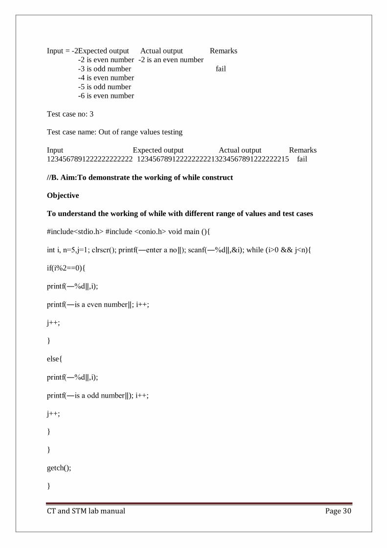
Test case no: 3
Test case name: Out of range values testing
Input Expected output Actual output Remarks
1234567891222222222222 123456789122222222213 234567891222222215 fail
//B. Aim:To demonstrate the working of while construct
Objective
To understand the working of while with different range of values and test cases
#include<stdio.h> #include <conio.h> void main (){
int i, n=5,j=1; clrscr(); printf(―enter a no‖); scanf(―%d‖,&i); while (i>0 && j<n){
if(i%2==0){
printf(―%d‖,i);
printf(―is a even number‖; i++;
j++;
}
else{
printf(―%d‖,i);
printf(―is a odd number‖); i++;
j++;
}
}
getch();
}

CT and STM lab manual Page 31
Input Actual output
2 2 is even number
3 is odd number
4 is even number
5 is odd number
6 is even number
Test cases:
Test case no: 1
Test case name: Positive values within range
Input =2 Expected output Actual output Remarks
2 is even number 2 is even number
3 is odd number 3 is odd number success
4 is even number 4 is even number
5 is odd number 5 is odd number
6 is even number 6 is even number
Test case no:2
Test case name: Negative values within a range
Input = -2
Expected output Actual output Remarks
-2 is even number -2 is an even number
-3 is odd number Fail
-4 is even number
-5 is odd number
-6 is even number
Test case no: 3
Test case name: Out of range values testing
Input Expected output Actual output Remarks
1234567891222222222222 123456789122222222213 234567891222222215 fail
//C. Aim: To demonstrate the working of if else construct
Objective
To understand the working of if else with different range of values and test cases

CT and STM lab manual Page 32
#include<stdio.h> #include <conio.h>
void main (){
int i; clrscr();
printf(―enter a number ‖); scanf(―%d‖,&i);
if(i%2==0){
printf(―%d‖,i);
printf(―is a even number‖);
}
else{
printf(―%d‖,i);
printf(―is a odd number‖);
}
getch();
}
Input Actual output
2 2 is even number
3 is odd number
4 is even number
5 is odd number
6 is even number
Test cases:
Test case no: 1
Test case name: Positive values within range
Input =2 Expected output Actual output Remarks
2 is even number 2 is even number
3 is odd number 3 is odd number success
4 is even number 4 is even number

CT and STM lab manual Page 33
5 is odd number 5 is odd number
6 is even number 6 is even number
Test case no:2
Test case name: Negative values within a range
Input = -2 Expected output Actual output Remarks
-2 is even number -2 is an even number
-3 is odd number fail
-4 is even number
-5 is odd number
-6 is even number
Test case no: 3
Test case name: Out of range values testing
Input Expected output Actual output Remarks
1234567891222222222222 123456789122222222213 234567891222222215 fail
// D. To demonstrate the working of switch construct
Objective
To understand the working of switch with different range of values and test cases
void main() {
int a,b,c; clrscr();
printf(―1.Add/n 2.Sub /n 3.Mul /n 4.Div /n Enter Your choice‖); scanf(―%d‖ , &i);
printf(―Enter a,b values‖); scanf(―%d%d‖,&a,&b); switch(i){
case 1: c=a+b;
printf(― The sum of a & b is: %d‖ ,c); break;
case 2: c=a-b;
printf(― The Diff of a & b is: %d‖ ,c); break;
case 3: c=a*b;
printf(― The Mul of a & b is: %d‖ ,c); break;
case 4: c=a/b;
printf(― The Div of a & b is: %d‖ ,c); break;
CT and STM lab manual Page 34
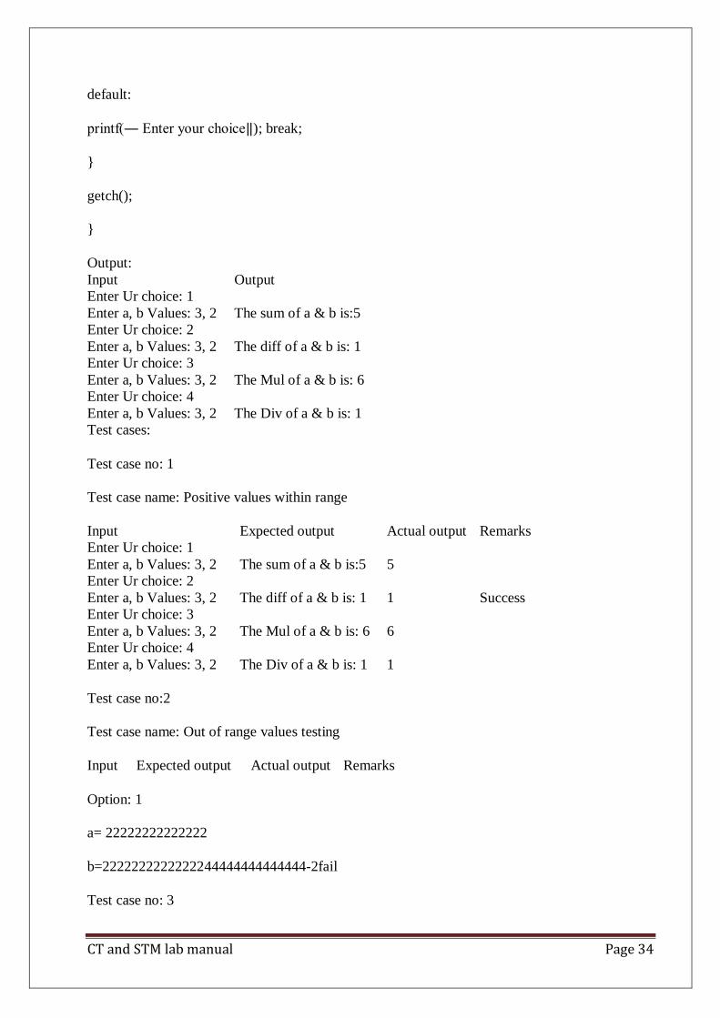
default:
printf(― Enter your choice‖); break;
}
getch();
}
Output:
Input Output
Enter Ur choice: 1
Enter a, b Values: 3, 2 The sum of a & b is:5
Enter Ur choice: 2
Enter a, b Values: 3, 2 The diff of a & b is: 1
Enter Ur choice: 3
Enter a, b Values: 3, 2 The Mul of a & b is: 6
Enter Ur choice: 4
Enter a, b Values: 3, 2 The Div of a & b is: 1
Test cases:
Test case no: 1
Test case name: Positive values within range
Input Expected output Actual output Remarks
Enter Ur choice: 1
Enter a, b Values: 3, 2 The sum of a & b is:5 5
Enter Ur choice: 2
Enter a, b Values: 3, 2 The diff of a & b is: 1 1 Success
Enter Ur choice: 3
Enter a, b Values: 3, 2 The Mul of a & b is: 6 6
Enter Ur choice: 4
Enter a, b Values: 3, 2 The Div of a & b is: 1 1
Test case no:2
Test case name: Out of range values testing
Input Expected output Actual output Remarks
Option: 1
a= 22222222222222
b=22222222222222 44444444444444 -2 fail
Test case no: 3
CT and STM lab manual Page 35
Test case name: Divide by zero
Input Expected output Actual output Remarks
Option: 4
a= 10 & b=0 error fail
// E. Aim: To demonstrate working of for construct
Objective
To understand the working of for with different range of values and test cases
#include <stdio.h> #include <conio.h>
void main (){ int i; clrscr();
printf(―enter a no‖); scanf(―%d‖,&i);
for(i=1;i<=5;i++){
if(i%2==0){ printf(―%d‖, i);
printf(― is a even no‖); i++;
}
else{
printf(―%d‖, i); printf(― is a odd no‖); i++;
}
}
getch();
}
Output:
Enter a no: 5
0 is a even no
1 is a odd no
2 is a even no
3 is a odd no

CT and STM lab manual Page 36
4 is a even no
5 is a odd no
Test cases:
Test case no: 1
Test case name: Positive values within range
Input =2 Expected output Actual output Remarks
0 is even number 0 is even number
1 is odd number 1 is odd number success
2 is even number 2 is even number
Test case no:2
Test case name: Negative values within a range
Input = -2 Expected output Actual output Remarks
0 is even number 0 is an even number
-1 is odd number -1 is even no fail
-2 is even number -2 is odd no
Test case no: 3
Test case name: Out of range values testing
Input Expected output Actual output Remarks
1234567891222222222222 123456789122222222213 234567891222222215 fail
2. Aim: A program written in c language for matrix multiplication fails “Introspect the
causes for its failure and write down the possible reasons for its failure”.
Objective: Understand the failures of matrix multiplication
#include<stdio.h>
#include<conio.h> void main()
{
int a[3][3],b[3][3],c[3][3],i,j,k,m,n,p,q; clrscr();
printf(― Enter 1st matrix no.of rows & cols‖) scanf(―%d%d‖,&m,&n);
printf(― Enter 2nd matrix no.of rows & cols‖) scanf(―%d%d‖,&p,&q);
printf("\n enter the matrix elements"); for(i=0;i<m;i++);
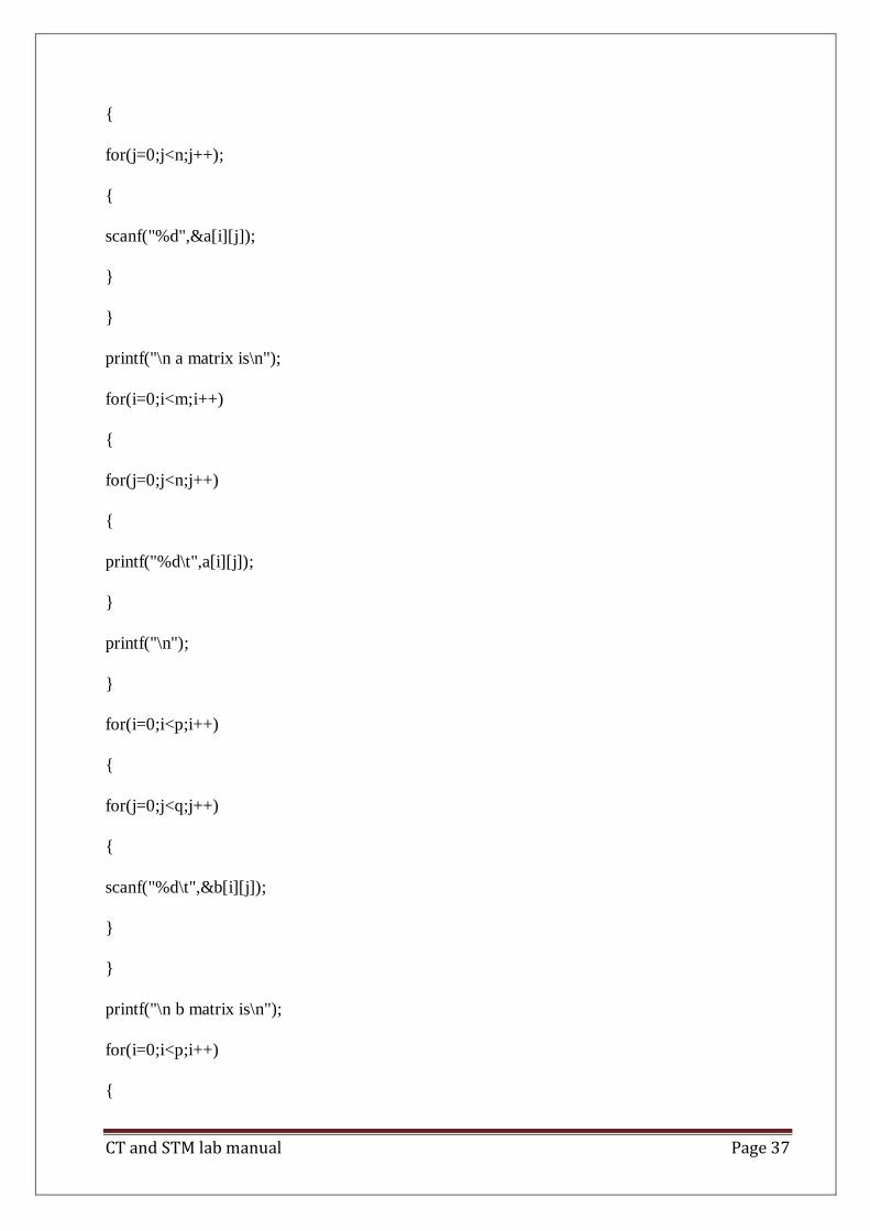
CT and STM lab manual Page 37
{
for(j=0;j<n;j++);
{
scanf("%d",&a[i][j]);
}
}
printf("\n a matrix is\n");
for(i=0;i<m;i++)
{
for(j=0;j<n;j++)
{
printf("%d\t",a[i][j]);
}
printf("\n");
}
for(i=0;i<p;i++)
{
for(j=0;j<q;j++)
{
scanf("%d\t",&b[i][j]);
}
}
printf("\n b matrix is\n");
for(i=0;i<p;i++)
{

CT and STM lab manual Page 38
for(j=0;j<q;j++)
{
printf("%d\t",b[i][j]);
}
printf("\n");
}
for(i=0;i<m;i++)
{
for(j=0;j<q;j++)
{
c[i][j]=0;
for(k=0;k<n;k++)
{
c[i][j]=c[i][j]+a[i][k]*b[k][j];
}
}
}
for(i=0;i<m;i++)
{
for(j=0;j<q;j++)
{
printf("%d\t",c[i][j]);
}
printf("\n");
}

CT and STM lab manual Page 39
getch();
}
Output:
Enter Matrix1: 1 1 1 1 1 1 1 1 1
Enter Matrix2: 1 1 1 1 1 1 1 1 1
Actual Output : 3 3 3 3 3 3 3 3 3
Test cases:
Test case no: 1
Test case name: Equal no.of rows & cols
Input Expected output Actual output Remarks
Matrix1 rows & cols= 3 3
Matrix2 rows & cols= 3 3
Matrix1: 1 1 1
1 1 1 3 3 3 3 3 3
1 1 1 3 3 3 3 3 3 Success
3 3 3 3 3 3
Matrix2: 1 1 1
1 1 1
1 1 1
Test case no:2
Test case name: Cols of 1st matrix not equal to rows of 2nd matrix
Input Expected output Actual output Remarks
Matrix1 rows & cols= 2 2 Operation Can„t be fail
Performed
Matrix2 rows & cols= 3 2
Test case no: 3
Test case name: Out of range values testing
Input Expected output Actual output Remarks
Matrix1 rows & cols= 2 2
Matrix2 rows & cols= 2 2
1234567891 2222222222 fail
2234567891 2222222221
234567891 22222221533
213242424 56456475457
CT and STM lab manual Page 40
Experiment : 3.
Name of the Experiment: ATM system specifications and report the various bugs
1) Insertion of ATM card with success.
2) Incorrect ATM Card Insertion – Leading to unsuccessful operation.
3) ATM Card of an invalid account – Leading to unsuccessful operation.
4) Successful feeding of ATM PIN Number.
5) Incorrect ATM PIN Number feeding 3 times - Leading to unsuccessful operation.
6) Selection of language of operation, with success.
7) Selection of Type of Bank Account with success.
8) Incorrect Bank Account type Selection in respect to the type of ATM Card inserted - Leading
to unsuccessful operation.
9) Selection of withdrawal option with success.
10) Selection of Amount to be withdrawn with success.
11) Incorrect Currency denominations - Leading to unsuccessful operation.
12) Successful completion of withdrawal of money.
13) Amount to be withdrawn in excess of the available Balance - Leading to unsuccessful
operation.
14) Shortage of Currency Notes in ATM - Leading to unsuccessful operation.
15) Amount to be withdrawn in excess of the daily withdrawal limit - Leading to unsuccessful
operation.
16) ATM link to the Bank Server not available at the moment - Leading to unsuccessful
operation.
17) Clicking of the Cancel button after inserting the ATM card - Leading to unsuccessful
operation.
18) Clicking of the Cancel button after feeding the ATM PIN Number - Leading to unsuccessful
operation.
19) Clicking of the Cancel button after selection of language of operation - Leading to
unsuccessful operation.
20) Clicking of the Cancel button after selection of Type of Bank Account - Leading to
unsuccessful operation.
21) Clicking of the Cancel button after selection of Amount of withdrawal - Leading to
unsuccessful operation.
22) Clicking of the Cancel button after feeding the amount to be withdrawn - Leading to
unsuccessful operation.

CT and STM lab manual Page 41
Experiment :4.
Name of the Experiment: Test cases for banking applications
AIM:
Banking applications are considered to be one of the most complex applications in today‟s
software development and testing industry. What makes Banking application so complex?
What approach should be followed in order to test the complex workflows involved? In this
article we will be highlighting different stages and techniques involved in testing Banking
applications. The characteristics of a Banking application are as follows:
Multi tier functionality to support thousands of concurrent user sessions
Large scale Integration , typically a banking application integrates with numerous other
applications such as Bill Pay utility and Trading accounts
Complex Business workflows
Real Time and Batch processing
High rate of Transactions per seconds
Secure Transactions
Robust Reporting section to keep track of day to day transactions
Strong Auditing to troubleshoot customer issues
Massive storage system
Disaster Management.
The above listed ten points are the most important characteristics of a Banking application.
Banking applications have multiple tiers involved in performing an operation. For Example, a
banking application may have:
1. Web Server to interact with end users via Browser
2. Middle Tier to validate the input and output for web server
3. Data Base to store data and procedures
4. Transaction Processor which could be a large capacity Mainframe or any other Legacy
system to carry out Trillions of transactions per second.

CT and STM lab manual Page 42
If we talk about testing banking applications it requires an end to end testing methodology
involving multiple software testing techniques to ensure:
Total coverage of all banking workflows and Business Requirements
Functional aspect of the application
Security aspect of the application
Data Integrity
Concurrency
User Experience
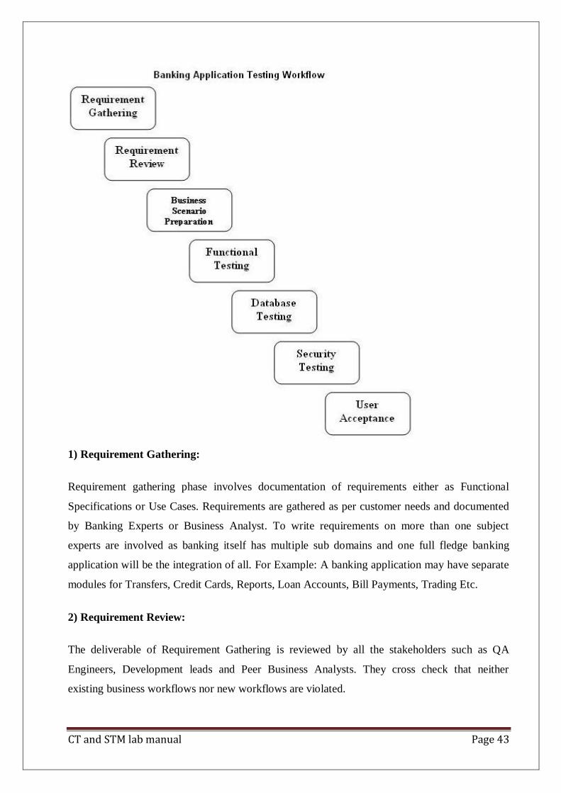
Typical stages involved in testing Banking Applications are shown in below workflow which
we will be discussing individually.
CT and STM lab manual Page 43
1) Requirement Gathering:
Requirement gathering phase involves documentation of requirements either as Functional
Specifications or Use Cases. Requirements are gathered as per customer needs and documented
by Banking Experts or Business Analyst. To write requirements on more than one subject
experts are involved as banking itself has multiple sub domains and one full fledge banking
application will be the integration of all. For Example: A banking application may have separate
modules for Transfers, Credit Cards, Reports, Loan Accounts, Bill Payments, Trading Etc.
2) Requirement Review:
The deliverable of Requirement Gathering is reviewed by all the stakeholders such as QA
Engineers, Development leads and Peer Business Analysts. They cross check that neither
existing business workflows nor new workflows are violated.
CT and STM lab manual Page 44
3) Business Scenario Preparations:
In this stage QA Engineers derive Business Scenarios from the requirement documents
(Functions Specs or Use Cases); Business Scenarios are derived in such a way that all Business
Requirements are covered. Business Scenarios are high level scenarios without any detailed
steps, further these Business Scenarios are reviewed by Business Analyst to ensure all of
Business Requirements are met and its easier for BAs to review high level scenarios than
reviewing low level detailed Test Cases.
4) Functional Testing:
In this stage functional testing is performed and the usual software testing activities are
performed such as:
Test Case Preparation:
In this stage Test Cases are derived from Business Scenarios, one Business Scenario leads to
several positive test cases and negative test cases. Generally tools used during this stage are
Microsoft Excel, Test Director or Quality Center.
Test Case Review:
Reviews by peer QA Engineers
Test Case Execution:
Test Case Execution could be either manual or automatic involving tools like QC, QTP or any
other.
5) Database Testing:
Banking Application involves complex transaction which are performed both at UI level and
Database level, Therefore Database testing is as important as functional testing. Database in
itself is an entirely separate layer hence it is carried out by database specialists and it uses
techniques like
Data loading
Database Migration
Testing DB Schema and Data types
Rules Testing
Testing Stored Procedures and Functions

CT and STM lab manual Page 45
Testing Triggers
Data Integrity
6) Security Testing:
Security Testing is usually the last stage in the testing cycle as completing functional and non
functional are entry criteria to commence Security testing. Security testing is one of the major
stages in the entire Application testing cycle as this stage ensures that application complies with
Federal and Industry standards. Security testing cycle makes sure the application does not have
any web vulnerability which may expose sensitive data to an intruder or an attacker and complies
with standards like OWASP.
In this stage the major task involves in the whole application scan which is carried out using
tools like IBM Appscan or HP WebInspect (2 Most popular tools).
Once the Scan is complete the Scan Report is published out of which False Positives are filtered
out and rest of the vulnerability are reported to Development team for fixing depending on the
Severity.
Other Manual tools for Security Testing used are: Paros Proxy, Http Watch, Burp Suite,
Fortify tools Etc.
Apart from the above stages there might be different stages involved like Integration Testing and
Performance Testing.
In today‟s scenario majority of Banking Projects are using: Agile/Scrum, RUP and
Continuous Integration methodologies, and Tools packages like Microsoft‟s VSTS and Rational
Tools.
As we mentioned RUP above, RUP stands for Rational Unified Process, which is an iterative
software development methodology introduced by IBM which comprises of four phases in which
development and testing activities are carried out.
Four phases are:
i)Inception
ii)Collaboration
CT and STM lab manual Page 46
iii) Construction and
iv) Transition
RUP widely involves IBM Rational tools.
In this article we discussed how complex a Banking application could be and what are the
typical phases involved in testing the application. Apart from that we also discussed current
trends followed by IT industries including software development methodologies and tools.

CT and STM lab manual Page 47
Experiment :5.
Name of the Experiment: Test plan document for library application
The Library Management System is an online application for assisting a librarian in managing a book
library in a University. The system would provide basic set of features to add/update clients, add/update
books, search for books, and manage check-in / checkout processes. Our test group tested the system
based on the requirement specification.
INTRODUCTION
This test report is the result for testing in the LMS. It mainly focuses on two problems: what we will
test and how we will test.
Result
GUI test
Pass criteria: librarians could use this GUI to interface with the backend library database without any
difficulties
Result: pass
Database test
Pass criteria: Results of all basic and advanced operations are normal (refer to section 4)
Result: pass
Basic function test
Add a student
Pass criteria:
Each customer/student should have following attributes: Student ID/SSN (unique), Name, Address
and Phone number.
Result: pass
The retrieved customer information by viewing customer detail should contain the four attributes.
Result: pass
Update/delete student
Pass criteria:

CT and STM lab manual Page 48
The record would be selected using the student ID
Result: pass
Updates can be made on full. Items only: Name, Address, Phone number
Result: pass
The record can be deleted if there are no books issued by user.
Result: Partially pass. When no books issued by user, he can be deleted. But when there are books
Issued by this user, he was also deleted. It is wrong.
The updated values would be reflected if the same customer's ID/SSN is called for.
Result: pass
If customer were deleted, it would not appear in further search queries.
Result: pass
Add a book
Pass criteria:
Each book shall have following attributes: Call Number, ISBN, Title, Author name.
Result: pass
The retrieved book information should contain the four attributes.
Result: pass
Update/delete book
Pass criteria:
The book item can be retrieved using the call number
Result: did not pass. Can not retrive using the call number
The data items which can be updated are: ISBN, Title, Author name
Result: pass
The book can be deleted only if no user has issued it.
Result: partially pass. When no user has issued it, pass. When there are user having issued it,
did not pass
The updated values would be reflected if the same call number is called for

CT and STM lab manual Page 49
Result: pass
If book were deleted, it would not appear in further search queries.
Result: pass
Search for book
Pass criteria:
The product shall let Librarian query books‘ detail information by their ISBN number or Author or
Title.
Result: pass
The search results would produce a list of books, which match the search parameters with following
Details: Call number, ISBN number, Title, Author
Result: pass
The display would also provide the number of copies which is available for issue
Result: pass
The display shall provide a means to select one or more rows to a user-list
Result: pass
A detailed view of each book should provide information about check-in/check out status, with the
borrower‘s information.
Result: pass
The search display will be restricted to 20 results per page and there would be means to navigate
from sets of search results.
Result: pass
The user can perform multiple searches before finally selecting a set of books for check in or
checkout. These should be stored across searches.
Result: pass
A book may have more than one copy. But every copy with the same ISBN number should have
same detail information.
Result: pass
The borrower‘s list should agree with the data in students‘ account
Result: pass

CT and STM lab manual Page 50
Check-in book
Pass criteria:
Librarians can check in a book using its call number
Result: pass
The check-in can be initiated from a previous search operation where user has selected a set of
books.
Result: pass
The return date would automatically reflect the current system date.
Result: did not pass.
Any late fees would be computed as difference between due date and return date at rate of 10 cents
a day.
Result: did not pass
A book, which has been checked in once, should not be checked in again
Result: pass
Check-out book
Pass criteria:
Librarians can check out a book using its call number
Result: pass
The checkout can be initiated from a previous search operation where user has selected a set of
books.
Result: pass
The student ID who is issuing the book would be entered
Result: pass
The issue date would automatically reflect the current system date.
Result: did not pass
The due date would automatically be stamped as 5 days from current date.
Result: did not pass
A book, which has been checked out once, should not be checked out again

CT and STM lab manual Page 51
Result: pass
A student who has books due should not be allowed to check out any books
Result: did not pass
The max. No of books that can be issued to a customer would be 10. The system should not allow
checkout of books beyond this limit.
Result: pass
View book detail
Pass criteria:
This view would display details about a selected book from search operation
Result: pass
The details to be displayed are: Call number, IBN, Title, Author, Issue status (In library or checked
out), If book is checked out it would display, User ID & Name, Checkout date, Due date
Result: for checkout date and due date, did not pass
Books checked in should not display user summary
Result: pass
Books checked out should display correct user details.
Result: pass
View student detail
Pass criteria:
Librarians can select a user record for detailed view
Result: pass
The detail view should show:
a.User name, ID, Address & Phone number
Result: pass
b. The books issued by user with issue date, due date, call number, title
Result: did not pass
c. Late fees & Fines summary and total
Result: did not pass

CT and STM lab manual Page 52
The display should match existing user profile
Result: pass
The books checked out should have their statuses marked
Result: pass
The book search query should show the user id correctly.
Result: pass
Network test
Pass criteria: Results of operations (ping, ftp and ODBC connectivity check) are normal
Result: did not test this item, because no enough machines and no available envirenment.
Experiment: 6
Name of the Experiment: Study of Any Testing Tool( WinRunner)

CT and STM lab manual Page 53
WinRunner is a program that is responsible for the automated testing of software. WinRunner
is a Mercury Interactive‘s enterprise functional testing tool for Microsoft windows
applications.
Importance of Automated Testing:
1. Reduced testing time
2. Consistent test procedures – ensure process repeatability and resource independence.
Eliminates errors of manual testing
3. Reduces QA cost – Upfront cost of automated testing is easily recovered over the
lifetime of the product
4. Improved testing productivity – test suites can be run earlier and more often
5. Proof of adequate testing
6. For doing Tedious work – test team members can focus on quality areas.
WinRunner Uses:
1. With WinRunner sophisticated automated tests can be created and run on an
application.
2. A series of wizards will be provided to the user, and these wizards can create tests in an
automated manner.
3. Another impressive aspect of WinRunner is the ability to record various interactions,
and transform them into scripts. WinRunner is designed for testing graphical user
interfaces.
4. When the user make an interaction with the GUI, this interaction can be recorded.
Recording the interactions allows to determine various bugs that need to be fixed.
5. When the test is completed, WinRunner will provide with detailed information
regarding the results. It will show the errors that were found, and it will also give
important information about them. The good news about these tests is that they can be
reused many times.
6. WinRunner will test the computer program in a way that is very similar to normal user
interactions. This is important, because it ensures a high level of accuracy and realism.
Even if an engineer is not physically present, the Recover manager will troubleshoot
any problems that may occur, and this will allow the tests to be completed without
errors.

CT and STM lab manual Page 54
7. The Recover Manager is a powerful tool that can assist users with various scenarios.
This is important, especially when important data needs to be recovered.
The goal of WinRunner is to make sure business processes are properly carried out.
WinRunner uses TSL, or Test Script Language.
WinRunner Testing Modes
Context Sensitive
Context Sensitive mode records your actions on the application being tested in terms of the
GUI objects you select (such as windows, lists, and buttons), while ignoring the physical
location of the object on the screen. Every time you perform an operation on the application
being tested, a TSL statement describing the object selected and the action performed is
generated in the test script. As you record, WinRunner writes a unique description of each
selected object to a GUI map.
The GUI map consists of files maintained separately from your test scripts. If the user interface
of your application changes, you have to update only the GUI map, instead of hundreds of
tests. This allows you to easily reuse your Context Sensitive test scripts on future versions of
your application.
To run a test, you simply play back the test script. WinRunner emulates a user by moving the
mouse pointer over your application, selecting objects, and entering keyboard input.
WinRunner reads the object descriptions in the GUI map and then searches in the application
being tested for objects matching these descriptions. It can locate objects in a window even if
their placement has changed.
Analog
Analog mode records mouse clicks, keyboard input, and the exact x- and y-coordinates
traveled by the mouse. When the test is run, WinRunner retraces the mouse tracks. Use Analog
mode when exact mouse coordinates are important to your test, such as when testing a drawing
application.
The WinRunner Testing Process

CT and STM lab manual Page 55
Testing with WinRunner involves six main stages:
1. Create the GUI Map
The first stage is to create the GUI map so WinRunner can recognize the GUI objects in the
application being tested. Use the RapidTest Script wizard to review the user interface of your
application and systematically add descriptions of every GUI object to the GUI map.
Alternatively, you can add descriptions of individual objects to the GUI map by clicking
objects while recording a test.
2. Create Tests
Next is creation of test scripts by recording, programming, or a combination
of both. While recording tests, insert checkpoints where we want to check the response of the
application being tested. We can insert checkpoints that check GUI objects, bitmaps, and
databases. During this process, WinRunner captures data and saves it as expected results—the
expected response of the application being tested.
3. Debug Tests
Rrun tests in Debug mode to make sure they run smoothly. One can set breakpoints, monitor
variables, and control how tests are run to identify and isolate defects. Test results are saved in
the debug folder, which can be discarded once debugging is finished.
When WinRunner runs a test, it checks each script line for basic syntax errors, like incorrect
syntax or missing elements in If, While, Switch, and For statements. We can use the Syntax
Check options (Tools >Syntax Check) to check for these types of syntax errors before
running your test.
4. Run Tests
Tests can be run in Verify mode to test the application. Each time WinRunner
encounters a checkpoint in the test script, it compares the current data of the application being
tested to the expected data captured earlier. If any mismatches are found, WinRunner captures
them as actual results.

CT and STM lab manual Page 56
5. View Results
Following each test run, WinRunner displays the results in a report. The report details all the
major events that occurred during the run, such as checkpoints, error messages, system
messages, or user messages.
If mismatches are detected at checkpoints during the test run, we can view the expected results
and the actual results from the Test Results window. In cases of bitmap mismatches, one can
also view a bitmap that displays only the difference between the expected and actual results.
We can view results in the standard WinRunner report view or in the Unified report view. The
WinRunner report view displays the test results in a Windows-style viewer. The Unified report
view displays the results in an HTML-style viewer (identical to the style used for QuickTest
Professional test results).
6. Report Defects
If a test run fails due to a defect in the application being tested, one can report information
about the defect directly from the Test Results window.
This information is sent via e-mail to the quality assurance manager, who tracks the defect
until it is fixed.
Using Winrunner Window
Before you begin creating tests, you should familiarize yourself with the WinRunner main
window.
1.4.1. To start WinRunner:
Choose Programs > WinRunner > WinRunner on the Start menu.
The first time you start WinRunner, the Welcome to WinRunner window and the ―What‘s New
in WinRunner‖ help open. From the Welcome window you can create a new test, open an
existing test, or view an overview of WinRunner in your default browser.

CT and STM lab manual Page 57
If you do not want this window to appear the next time you start WinRunner, clear the Show
on Startup check box. To show the Welcome to WinRunner window upon startup from
within WinRunner, choose Settings > General Options, click the Environment tab, and
select the Show Welcome screen check box.
1.4.2. The Main WinRunner Window
The main WinRunner window contains the following key elements:
WinRunner title bar
Menu bar, with drop-down menus of WinRunner commands
Standard toolbar, with buttons of commands commonly used when running a test
User toolbar, with commands commonly used while creating a test
Status bar, with information on the current command, the line number of the insertion
point and the name of the current results folder
The Standard toolbar provides easy access to frequently performed tasks, such as opening,
executing, and saving tests, and viewing test results.
Standard Toolbar
The User toolbar displays the tools you frequently use to create test scripts. By default, the
User toolbar is hidden. To display the User toolbar, choose Window > User Toolbar. When
you create tests, you can minimize the WinRunner window and work exclusively from the
toolbar.
The User toolbar is customizable. You choose to add or remove buttons using the Settings >
Customize User Toolbar menu option. When you re-open WinRunner, the User toolbar
appears as it was when you last closed it.
The commands on the Standard toolbar and the User toolbar are described in detail in
subsequent lessons.
Note that you can also execute many commands using softkeys. Softkeys are keyboard
shortcuts for carrying out menu commands. You can configure the softkey combinations for

CT and STM lab manual Page 58
your keyboard using the Softkey Configuration utility in your WinRunner program group. For
more information, see the ―WinRunner at a Glance‖ chapter in your WinRunner User’s Guide.
Now that you are familiar with the main WinRunner window, take a few minutes to explore
these window components before proceeding to the next lesson.
The Test Window
You create and run WinRunner tests in the test window. It contains the following
key elements:
Test window title bar, with the name of the open test
Test script, with statements generated by recording and/or programming in TSL,
Mercury Interactive‘s Test Script Language
Execution arrow, which indicates the line of the test script being executed during a test
run, or the line that will next run if you select the Run from arrow option
Insertion point, which indicates where you can insert or edit text
7. Study of any web testing tool (e.g. Selenium)
Selenium is a robust set of tools that supports rapid development of test automation for web-
based applications. Selenium provides a rich set of testing functions specifically geared to the
needs of testing of a web application. These operations are highly flexible, allowing many
options for locating UI elements and comparing expected test results against actual application
behavior.
One of Selenium‘s key features is the support for executing one‘s tests on multiple browser
platforms.
Selenium Components
Selenium is composed of three major tools. Each one has a specific role in aiding the
development of web application test automation.

CT and STM lab manual Page 59
Selenium-IDE
Selenium-IDE is the Integrated Development Environment for building Selenium test cases. It
operates as a Firefox add-on and provides an easy-to-use interface for developing and running
individual test cases or entire test suites. Selenium-IDE has a recording feature, which will
keep account of user actions as they are performed and store them as a reusable script to play
back. It also has a context menu (right-click) integrated with the Firefox browser, which allows
the user to pick from a list of assertions and verifications for the selected location. Selenium-
IDE also offers full editing of test cases for more precision and control.
Although Selenium-IDE is a Firefox only add-on, tests created in it can also be run against
other browsers by using Selenium-RC and specifying the name of the test suite on the
command line.
Selenium-RC (Remote Control)
Selenium-RC allows the test automation developer to use a programming language for
maximum flexibility and extensibility in developing test logic. For instance, if the application
under test returns a result set, and if the automated test program needs to run tests on each
element in the result set, the programming language‘s iteration support can be used to iterate
through the result set, calling Selenium commands to run tests on each item.
Selenium-RC provides an API (Application Programming Interface) and library for each of its
supported languages: HTML, Java, C#, Perl, PHP, Python, and Ruby. This ability to use
Selenium-RC with a high-level programming language to develop test cases also allows the
automated testing to be integrated with a project‘s automated build environment.
Selenium-Grid
Selenium-Grid allows the Selenium-RC solution to scale for large test suites or test suites that
must be run in multiple environments. With Selenium-Grid, multiple instances of Selenium-RC
are running on various operating system and browser configurations; Each of these when
launching register with a hub. When tests are sent to the hub they are then redirected to an
available Selenium-RC, which will launch the browser and run the test. This allows for running
tests in parallel, with the entire test suite theoretically taking only as long to run as the longest
individual test.

CT and STM lab manual Page 60
* Tests developed on Firefox via Selenium-IDE can be executed on any other supported
browser via a simple Selenium-RC command line.
** Selenium-RC server can start any executable, but depending on browser security settings
there may be technical limitations that would limit certain features.
Flexibility and Extensibility
Selenium is highly flexible. There are multiple ways in which one can add functionality to
Selenium‘s framework to customize test automation for one‘s specific testing needs. This is,
perhaps, Selenium‘s strongest characteristic when compared with proprietary test automation
tools and other open source solutions. Selenium-RC support for multiple programming and
scripting languages allows the test writer to build any logic they need into their automated
testing and to use a preferred programming or scripting language of one‘s choice.
Selenium-IDE allows for the addition of user-defined ―user-extensions‖ for creating additional
commands customized to the user‘s needs. Also, it is possible to re-configure how the
Selenium-IDE generates its Selenium-RC code. This allows users to customize the generated
code to fit in with their own test frameworks. Finally, Selenium is an Open Source project
where code can be modified and enhancements can be submitted for contribution.
.Test Suites
A test suite is a collection of tests. Often one will run all the tests in a test suite as one
continuous batch-job.
When using Selenium-IDE, test suites also can be defined using a simple HTML file. The
syntax again is simple. An HTML table defines a list of tests where each row defines the
filesystem path to each test. An example tells it all.
<html>
<head>
<title>Test Suite Function Tests – Priority 1</title> </head>

CT and STM lab manual Page 61
<body>
<table>
<tr><td><b>Suite Of Tests</b></td></tr>
<tr><td><a href=‖./Login.html‖>Login</a></td></tr>
<tr><td><a href=‖./SearchValues.html‖>Test Searching for Values</a></td></tr>
<tr><td><a href=‖./SaveValues.html‖>Test Save</a></td></tr>
</table> </body>
</html>
A file similar to this would allow running the tests all at once, one after another, from the
Selenium-IDE.
Test suites can also be maintained when using Selenium-RC. This is done via programming
and can be done a number of ways. Commonly Junit is used to maintain a test suite if one is
using Selenium-RC with Java. Additionally, if C# is the chosen language, Nunit could be
employed. If using an interpreted language like Python with Selenium-RC than some simple
programming would be involved in setting up a test suite. Since the whole reason for using Sel-
RC is to make use of programming logic for your testing this usually isn‘t a problem.
Few typical Selenium commands.
open – opens a page using a URL.
click/clickAndWait – performs a click operation, and optionally waits for a new page to load.
verifyTitle/assertTitle – verifies an expected page title.
verifyTextPresent – verifies expected text is somewhere on the page.
verifyElementPresent – verifies an expected UI element, as defined by its HTML tag, is
present on the page.
CT and STM lab manual Page 62
verifyText – verifies expected text and it‘s corresponding HTML tag are present on the page.
verifyTable – verifies a table‘s expected contents.
waitForPageToLoad – pauses execution until an expected new page loads. Called
automatically when clickAndWait is used.
waitForElementPresent – pauses execution until an expected UI element, as defined by its
HTML tag, is present on the page.
8.Study of Any Bug Tracking Tool (Bugzilla)
Bugzilla is a ―Bug Tracking System‖ that can efficiently keep track of outstanding bugs in a
product. Multiple users can access this database and query, add and manage these bugs.
Bugzilla essentially comes to the rescue of a group of people working together on a product as
it enables them to view current bugs and make contributions to resolve issues.
Its basic repository nature works out better than the mailing list concept and an organized
database is always easier to work with.
Advantage of Using Bugzilla:
1. Bugzilla is very adaptable to various situations. Known uses currently include IT support
queues, Systems Administration deployment management, chip design and development
problem tracking (both pre-and-post fabrication), and software and hardware bug tracking for
luminaries such as Redhat, NASA, Linux-Mandrake, and VA Systems. Combined with
systems such as CVS, Bugzilla provides a powerful, easy-to-use solution to configuration
management and replication problems.
2. Bugzilla can dramatically increase the productivity and accountability of individual
employees by providing a documented workflow and positive feedback for good performance.
Ultimately, Bugzilla puts the power in user‘s hands to improve value to business while
providing a usable framework for natural attention to detail and knowledge store to flourish.
The bugzilla utility basically allows to do the following:
Add a bug into the database
CT and STM lab manual Page 63
Review existing bug reports
Manage the content
Bugzilla is organised in the form of bug reports that give all the information needed about a
particular bug. A bug report would consist of the following fields.
Product–>Component
Assigned to
Status (New, Assigned, Fixed etc)
Summary
Bug priority
Bug severity (blocker, trivial etc)
Bug reporter
Using Bugzilla:
Bugzilla usage involves the following activities
Setting Parameters and Default Preferences
Creating a New User
Impersonating a User
Adding Products
Adding Product Components
Modifying Default Field Values
Creating a New Bug
Viewing Bug Reports
Setting Parameters and Default Preferences:
When we start using Bugzilla, we‘ll need to set a small number of parameters and preferences.
At a minimum, we should change the following items, to suit our particular need:
▪ Set the maintainer
▪ Set the mail_delivery_method
CT and STM lab manual Page 64
▪ Set bug change policies
▪ Set the display order of bug reports
To set parameters and default preferences:
1. Click Parameters at the bottom of the page.
2. Under Required Settings, add an email address in the maintainer field.
3. Click Save Changes.
4. In the left side Index list, click Email.
5. Select from the list of mail transports to match the transport we‘re using. If evaluating
a click2try application, select Test. If using SMTP, set any of the other SMTP options
for your environment. Click Save Changes.
6. In the left side Index list, click Bug Change Policies.
7. Select On for commentoncreate, which will force anyone who enters a new bug to enter
a comment, to describe the bug. Click Save Changes.
8. Click Default Preferences at the bottom of the page.
9. Select the display order from the drop-down list next to the When viewing a bug, show
comments in this order field. Click Submit Changes.
Creating a New User
Before entering bugs, make sure we add some new users. We can enter users very easily, with
a minimum of information. Bugzilla uses the email address as the user ID, because users are
frequently notified when a bug is entered, either because they entered the bug, because the bug
is assigned to them, or because they‘ve chosen to track bugs in a certain project.
To create a new user:
1. Click Users.
2. Click add a new user.
3. Enter the Login name, in the form of an email address.
4. Enter the Real name, a password, and then click Add.
5. Select the Group access options. we‘ll probably want to enable the following options
in the row titled User is a member of these groups:

CT and STM lab manual Page 65
canconfirm
editbugs
editcomponents
6. Click Update when done with setting options.
Impersonating a User
Impersonating a user is possible, though rare, that we may need to file or manage a bug in an
area that is the responsibility of another user when that user is not available. Perhaps the user is
on vacation, or is temporarily assigned to another project. We can impersonate the user to
create or manage bugs that belong to that user.
Adding Products
We‘ll add a product in Bugzilla for every product we are developing. To start with, when we
first login to Bugzilla, we‘ll find a test product called TestProduct. We should delete this and
create a new product.
To add a product:
1. At the bottom of the page, click Products.
2. In the TestProduct listing, click Delete.
3. Click Yes, Delete.
4. Now click Add a product.
5. Enter a product name, such as ―Widget Design Kit.‖
6. Enter a description.
7. Click Add. A message appears that you‘ll need to add at least one component.
Adding Product Components
Products are comprised of components. Software products, in particular, are typically made up
of many functional components, which in turn are made up of program elements, like classes
and functions. It‘s not unusual in a software development team environment for different
individuals to be responsible for the bugs that are reported against a given component. Even if
there are other programmers working on that component, it‘s not uncommon for one person,
CT and STM lab manual Page 66
either a project lead or manager, to be the gatekeeper for bugs. Often, they will review the bugs
as they are reported, in order to redirect them to the appropriate developer or even another
team, to review the priority and severity supplied by the reporter, and sometimes to reject bugs
as duplicates or enhancement requests, for example.
To add a component:
1. Click the link add at least one component in the message that appears after creating a
new product.
2. Enter the Component name.
3. Enter a Description.
4. Enter a default assignee. Use one of the users we‘ve created. Remember to enter the
assignee in the form of an email address.
5. Click Add.
6. To add more components, click the name of product in the message that reads edit
other components of product <product name>.
Modifying Default Field Values
Once we begin to enter new bugs, we‘ll see a number of drop-down lists containing default
values. Some of these may work just fine for our product. Others may not. We can modify the
values of these fields, adding new values and deleting old ones. Let‘s take a look at the OS
category.
To modify
To modify default field values:
1. At the bottom of the page, in the Edit section, click Field Values.
2. Click the link, in this case OS, for the field we want to edit. The OS field contains a list
of operating system names. We are going to add browsers to this list. In reality, we
might create a custom field instead, but for the sake of this example, just add them to
the OS list.
3. Click Add a value. In the Value field, enter ―IE7.‖ Click Add.

CT and STM lab manual Page 67
4. Click Add a value again.
5. In the Value field, enter ―Firefox 3.‖
6. Click Add.
7. Where it reads Add other values for the op_sys field, click op_sys.
8. This redisplays the table. We should now see the two new entries at the top of the table.
These values will also appear in the OS drop-down list when we create a new bug.
Creating a New Bug
Creating bugs is a big part of what Bugzilla does best.
To create a new bug:
1. In the top menu, click New.
2. If we‘ve defined more than one component, choose the component from the component
list.
3. Select a Severity and a Priority. Severity is self-explanatory, but Priority is generally
assumed to be the lower the number, the higher the priority. So, a P1 is the highest
priority bug, a showstopper.
4. Click the OS drop-down list to see the options, including the new browser names we
entered.
5. Select one of the options.
6. Enter a summary and a description. We can add any other information of choice, but it
is not required by the system, although we may determine that our bug reporting policy
requires certain information.
7. Click Commit. Bugzilla adds our bug report to the database and displays the detail
page for that bug.
Viewing Bug Reports
Eventually, we‘ll end up with thousands of bugs listed in the system. There are several ways to
view the bugs. The easiest is to click the My Bugs link at the bottom of the page. Because
we‘ve only got one bug reported, we‘ll use the standard Search function.
To find a bug:

CT and STM lab manual Page 68
1. Click Reports.
2. Click the Search link on the page, not the one in the top menu. This opens a page titled
―Find a Specific Bug.‖
3. Select the Status.
4. Select the Product.
5. Enter a word that might be in the title of the bug.
6. Click Search. If any bugs meet the criteria that we have entered, Bugzilla displays
them in a list summary.
1. Click the ID number link to view the full bug report.
Modifying Bug Reports
Suppose we want to change the status of the bug. We‘ve reviewed it and have determined that
it belongs to one of the users we have created earlier
To modify a bug report:
1. Scroll down the full bug description and enter a comment in the Additional Comments
field.
2. Select ―Reassign bug to‖ and replace the default user ID with one of the other user IDs
you created. It must be in the format of an email address.

CT and STM lab manual Page 69
9.Study of Any Test Management Tool ( TestDirector)
Test Director is a global test management solution which provides communication,
organization, documentation and structure to the testing project.
Test Director is used for
Mapping Requirements to User acceptance test cases
Test Planning by placing all the test cases and scripts in it.
Manual testing by defining test steps and procedures
Test Execution status
Defect Management
The TestDirector Testing Process
TestDirector offers an organized framework for testing applications before they are deployed.
Since test plans evolve with new or modified application requirements, you need a central data
repository for organizing and managing the testing process. TestDirector guides through the
requirements specification, test planning, test execution, and defect tracking phases of the
testing process.
The TestDirector testing process includes four phases:
Specifying Requirements
Requirements are linked to tests and defects to provide complete traceability and aid the
decision-making process
See what percent of requirements are covered by tests
Each requirement in the tree is described in detail, and can include any relevant
attachments. The QA tester assigns the requirement a priority level which is taken into
consideration when the test team creates the test plan
Import from Microsoft Word or third party RM tool
Planning Tests

CT and STM lab manual Page 70
The Test Plan Manager enables to divide application according to functionality.
Application can be divided into units, or subjects, by creating a test plan tree.
Define subjects according to:
o Application functionality-such as editing, file operations, and reporting
o Type of testing-such as functional, user interface, performance, and load
As the tests are also linked to defects, this helps ensure compliance with testing
requirements throughout the testing process
Running Tests
As the application constantly changes, using test lab, run manual and automated tests
in the project in order to locate defects and assess quality.
By creating test sets and choosing which tests to include in each set, test suite can be
created. A test set is a group of tests in a TestDirector project database designed to
achieve specific testing goals.
Tests can be run manually or scheduled to run automatically based on application
dependencies.
Tracking Defects
Locating and repairing application defects efficiently is essential to the testing process. Defects
can be detected and added during all stages of the testing process. In this phase you perform
the following tasks:
This tool features a sophisticated mechanism for tracking software defects, enabling
Testing Team and the project Team to monitor defects closely from initial detection
until resolution
By linking TestDirector to e-mail system, defect tracking information can be shared by
all Development and Management Teams, Testing and Wipro Software Quality
Assurance personnel
System Requirements for TestDirector
CT and STM lab manual Page 71
Server System configuration : 128 MB of RAM , 500 MB of free disk space, Win NT server,
Win 2K server, IIS 5.0, MSAccess/Oracle 7.x,8.x,9/MS SQL Server
Client System configuration : 64 MB of RAM , 10 MB of free disk space, Win
95/98/NT/2K/XP, IE 5 , Netscape 4.7
10. Study of any open source testing tool (TestLink)
Testlink is an open source test management tool. It enables creation and organization of test
cases and helps manage into test plan. Allows execution of test cases from test link itself. One
can easily track test results dynamically, generate reports, generate test metrics,prioritize test
cases and assign unfinished tasks.
Its a web based tool with GUI, which provides an ease to develop test cases, organize test cases
into test plans, execute these test cases and generate reports.
Test link exposes API, written in PHP, can help generate quality assurance dashboards. The
functions like AddTestCase ToTestPlan, Assign Requirements,Create TestCase etc. helps
create and organize test cases per test plan. Functions like GetTestCasesForTestPlan,
GetLastExecutionResult allows one to create quality assurance dashboard.
TestLink enables easily to create and manage Test cases as well as organize them into Test
plans. These Test plans allow team members to execute Test cases and track test results
dynamically, generate reports, trace software requirements, prioritize and assign tasks. Read
more about implemented features and try demo pages.
Overall structure
There are three cornerstones: Product, Test Plan and User. All other data are relations or
attributes for this base. First, definition of a couple of terms that are used throughout the
documentation.
Products and Test Plans

CT and STM lab manual Page 72
Product: A Product is something that will exist forever in TestLink. Products will undergo
many different versions throughout their life times. Product includes Test Specification with
Test Cases and should be sorted via Keywords.
Test Plan: Test Plans are created when you‘d like to execute test cases. Test plans can be made
up of the test cases of one or many Products. Test Plan includes Builds, Test Case Suite and
Test Results.
User: An User has a Role, that defines available TestLink features.
Test Case Categorization
TestLink breaks down the test case structure into three levels Components, Categories, and test
cases. These levels are persisted throughout the application.
Component: Components are the parents of Categories. Each Component can have many
Categories.
Category: Categories are the parents of test cases. Each Category can have many test cases.
Test Case: Test cases are the fundamental piece of TestLink.
Test Specification: All Components, Categories and test cases within Product.
Test Case Suite: All Components, Categories and test cases within Test Plan.
Test Specification
Creating Test Cases
Tester must follow this structure: Component, Category and test case. At first you create
Component(s) for your Product. Component includes Categories. Category has the similar
meaning but is second level of Test Specification and includes just Test Cases.
User can also copy or move Test Cases.
Test Cases has following parts:

CT and STM lab manual Page 73
• Title: could include either short description or abbreviation (e.g. TL-USER-LOGIN)
• Summary: should be really short; just for overview.
• Steps: describe test scenario (input actions); can also include precondition and cleanup
information here.
• Expected results: describe checkpoints and expected behaviour a tested Product or
system.
Deleting Test Cases
Test cases, Categories, and Components may be deleted from a test plan by users with lead
permissions from the ―delete test cases‖ screen. Deleting data may be useful when first creating
a test plan since there are no results. However, Deleting test cases will cause the loss of all
results associated with them. Therefore, extreme caution is recommended when using this
functionality.
Requirements relation
Test cases could be related with software/system requirements as n to n. The functionality must
be enabled for a Product. User can assign Test Cases and Requirements via link Assign
Requirements in the main screen.
Test Plans
Test plan contains name, description, collection a chosen test cases, builds, test results,
milestones, tester assignment and priority definition.
Creating a new Test Plan
Test Plans may be deleted from the ―Create test plan‖ page (link ―Create Test Plan‖) by users
with lead privileges. Test plans are the basis for test case execution. Test plans are made up of
test cases imported from Products at a specific point of time. Test plans can only be created by
users with lead privileges. Test plans may be created from other test plans. This allows users to
create test plans from test cases that at a desired point in time. This may be necessary when

CT and STM lab manual Page 74
creating a test plan for a patch. In order for a user to see a test plan they must have the propper
rights. Rights may be assigned (by leads) in the define User/Project Rights section. This is an
important thing to remember when users tell you they can‘t see the project they are working
on.
Test Execution
Test execution is available when:
1. A Test Specification is written.
2. A Test Plan is created.
3. Test Case Suite (for the Test Plan) is defined.
4. A Build is created.
5. The Test plan is assigned to testers (otherwise they cannot navigate to this Test Plan).
Select a required Test Plan in main page and navigate to the ‗Execute tests‘ link. Left pane
serves for navigation in Test Case Suite via tree menu, filtering and define a tested build.
Test Status
Execution is the process of assigning a result (pass, fail, blocked) to a test case for a specific
build. ‗Blocked‘ test case is not possible to test for some reason (e.g. a problem in
configuration disallows to run a tested functionality).
Insert Test results
Test Results screen is shown via click on an appropriate Component, Category or test case in
navigation pane. The title shows the current build and owner. The colored bar indicate status of
the test case. Yellow box includes test scenario of the test case.
Updated Test Cases: If users have the proper rights they can go to the ―Update modified test
case‖ page through the link on main page. It is not necessary for users to update test cases if
there has been a change (newer version or deleted).
CT and STM lab manual Page 75
Advantages:
1. Easy in tracking test cases(search with keyword, test case id, version etc)
2. We can add our custom fields to test cases.
3. Allocating the work either test case creation/execution any kind of documents is easy
4. when a test cases is updated the previous version also can be tracked
5. We can generate results build wise
6. Test plans are created for builds and work allocations can be done.
7. Report, is one of the awesome functionality present in the Test link, it generates reports in
desired format like HTML/ CSV /Excel and we can create graphs too.
8. And the above all is done on the privileges based which is an art of the testlink and i liked
this feature much
Example of TestLink workflow:
1. Administrator create a Product ―Fast Food‖ and a user Adam with rights ―leader‖ and Bela
with rights ―Senior tester‖.
2. Adam imports Software Requirements and for part of these requirements generates empty
Test cases.
3. Bela describe test sneario of these Test cases that are organized according to Components
and Categories.
4. Adam creates Keyword: ―Regression‖ and assignes this keyword to ten of these test cases.
5. Adam creates a Test Plan ―Fish & Chips‖, Build ―Fish 0.1‖ and add Test Cases with
keywords ―Regression‖.
6. Adam and Bela execute and record the testing with result: 5 passed, 1 failed and 4 are
blocked.
7. Developers make a new build ―Fish 0.2‖ and Bela tests the failed and blocked test cases
only. Exceptionaly all these five Test cases passed.
8. Manager would like to see results. Administrator explain him that he can create account
himself on the login page. Manager do it. He has ―Guest‖ rights and could see results and Test

CT and STM lab manual Page 76
cases. He can see that everything passed in overal report and problems in build ―Fish 0.1‖
in a report for particular Build. But he can change nothing.


![Cse-IV-unix and Shell Programming [10cs44]-Solution](https://static.fdocuments.us/doc/165x107/55cf9d53550346d033ad2205/cse-iv-unix-and-shell-programming-10cs44-solution.jpg)


![Cse-IV-unix and Shell Programming [10cs44]-Notes](https://static.fdocuments.us/doc/165x107/55cf8de4550346703b8c67df/cse-iv-unix-and-shell-programming-10cs44-notes-569841be5984a.jpg)