CSE 461: Final Review
69
CSE 461: Final Review Spring 2021
Transcript of CSE 461: Final Review

CSE 461: Final ReviewSpring 2021

Administrivia
● Project 3 due yesterday, but late days available
● Final Thursday, 6/10○ Have all day to do it!
2

Final Review Section
● Today: A brief review of lecture materials
○ Concepts, Protocols, Algorithms, …
● What YOU should do after this section and before the exam:
○ Go through the lecture slides
○ Think about the problems that each protocol/algorithm tries to solve
■ Pros and cons of current approaches?
■ Any other possible solutions?
■ What has not been solved yet?
3

Networks Overview
● Parts of a network● Types of links● Key interfaces● Sockets● Traceroute● Protocols and layers● Encapsulation
4

Parts of a Network
● Parts of a Network
● Types of Links Simplex
Full-duplex
Half-duplex
5

Protocols and Layers
Purpose Example Protocols
Application Programs that use network service HTTP, DNS
Transport Provides end-to-end data delivery TCP, UDP
Network Sends packets across multiple networks IP
Link Sends frames across a link Ethernet, Wi-Fi
Physical Transmit bits --
6

Protocols and Layers
Advantages
● Use information hiding to connect different systems
● Information reuse to build new protocols
Disadvantages
● Adds overhead● Hides information
7

Encapsulation
8

Network Layer● Network Service Models
● IP Address and Forwarding
● DHCP, ARP, ICMP
● NAT, IPv6
● Routing Algorithms
● BGP
9

Motivation
● What does the network layer do?
○ Connect different networks (send packets over multiple networks)
● Why do we need the network layer?
○ Switches don’t scale to large networks
○ Switches don’t work across more than one link layer technology
○ Switches don’t give much traffic control
10

Network Service Models
11
Datagrams Virtual Circuits
Connectionless service Connection-oriented service
No setup Connection setup required
Packets contain destination address Packets contain label for circuit
Routers looks up address in its forwarding table to determine next hop
Router looks up circuit in forwarding table to determine next hop
Example: IP Example: MPLS

Internetworking - IP
● How do we connect different networks together?
● IP - Internet Protocol
● Lowest Common Denominator
○ Asks little of lower-layer networks
○ Gives little as a higher layer service
12

IP Addresses Prefix and Forwarding
● IP prefix a.b.c.d/L
○ Represents addresses that have the same first L bits
○ e.g. 128.13.0.0/16 -> all 65536 addresses between 128.13.0.0 to 128.13.255.255
○ e.g. 18.31.0.0/32 -> 18.31.0.0 (only one address)
● Longest Matching Prefix
○ Find the longest prefix that
contains the destination address,
i.e., the most specific entry
13

DHCP - Dynamic Host Configuration Protocol
● Bootstrapping problem
● Leases IP address to nodes
● UDP
● Also setup other parameters:○ DNS server
○ IP address of local router
○ Network prefix
14

ARP - Address Resolution Protocol
● MAC is needed to send a
frame over the local link
● ARP to map an IP to MAC
● Sits on top of link layer
15
An ARP from my computer

ICMP - Internet Control Message Protocol
● Provides error reporting and testing
● Companion protocol to IP
● Traceroute, Ping
16

NAT - Network Address Translation
● One solution to IPv4 address exhaustion
● Map many private IP to one public IP, with
different port number
● Pros: useful functionality (firewall), easy to
deploy, etc.
● Cons: Connectivity has been broken!
● Many other cons...
17

IPv6
● A much better solution to IPv4 address exhaustion
● Uses 128-bit addresses, with lots of other changes
● IPv6 version protocols: NDP -> ARP, SLAAC -> DHCP
● Problem: being incompatible with IPv4. Solution: Tunnelling
18

Routing
● The process of deciding in which direction to send traffic
● Delivery models: unicast, broadcast, multicast, anycast
● Goals: correctness, efficient paths, fair paths, fast convergence, scalability
● Rules: decentralized, distributed setting
19

Techniques to Scale Routing
Hierarchical Routing
● Route first to the region, then to the IP prefix within the region
IP Prefix Aggregation and Subnets
● Adjusting the size of IP prefixes
○ Internally split one large prefix
○ Externally join multiple IP prefixes
20

Best Path Routing
Distance Vector Routing
Each node maintains a vector of distances and
next hops to all destinations.
Problems: Count-to-infinity scenario when
removing links.
Link State Routing (widely used)
Phase 1. Topology Dissemination: Each node
floods neighboring links. They learn full topology.
Phase 2. Route Computation: Each node runs
Dijkstra algorithm (or equivalent)
Algorithm details available in lecture slides
21

BGP - Border Gateway Protocol
● Internet-wide routing between ISPs (ASes)
○ Each has their own policy decisions
● Peer and Transit (Customer) relationship
● Border routers of ISPs announce BGP routes only to other parties
who may use those paths.
● Border routers of ISPs select the best path of the ones they hear in
any, non-shortest way
22

BGP example
● Transit (Provider & Customer)
○ Provider announces everything it can reach to its
customer
■ AS1 to AS2: AS1 advertises route to AS4
○ Customer only announces its customers to provider
■ AS2 to AS1: AS2 advertises route to A
● Peer (ISP 1 & ISP 2)
○ ISP 1 only announces its customer to ISP 2 and vice
versa, (not provider routes or other peers)
■ AS2 to AS3: AS2 advertises route to A
■ AS3 does not advertise route to A to AS4
23

Transport Layer● Service Models
● TCP vs UDP
● TCP Connections
● Flow Control and Sliding Window
● TCP Congestion Control
● Newer TCP Implementations
24

Service Models
● Transport Layer Services
○ Datagrams (UDP): Unreliable Messages
○ Streams (TCP): Reliable Bytestreams
● Socket API: simple abstraction to use the network
○ Port: Identify different applications / application layer protocols on a host
25

TCP vs UDP
26

TCP Connection Establishment and Release

Flow Control - Sliding Window Protocol
● Instead of stop-and-wait, sends W packets per 1 RTT
○ To fill network path, W = B * RTT / packet_size
● Receiver sends ACK upon receiving packets
○ Go-Back-N (similar to project 1 stage b): not efficient
○ Selective Repeat
■ Receiver passes data to app in order, and buffers out-of-order segments to reduce
retransmissions
■ ACK conveys highest in-order segment
● As well as hints about out-of-order segments
● Selective Retransmission on sender’s side
28

Flow Control - ACK Clock
29
1
2
3
4

Flow Control - Sliding Window Protocol (2)
● Flow control on receiver’s side
○ In order to avoid loss caused by user application not calling recv(), receiver
tells sender its available buffer space (WIN)
○ Sender uses lower of the WIN and W as the effective window size
● How to set a timeout for retransmission on sender’s side?
○ Adaptively determine timeout value based on smoothed estimate of RTT
30

Max-Min Fair Allocation
1. Start with all flows at rate 0
2. Increase the flows until there is a new bottleneck in the network
3. Hold fixed the rate of the flows that are bottlenecked
4. Go to step 2 for any remaining flows
31

TCP Bandwidth Allocation
● Closed loop: use feedback to adjust rates
○ NOT open loop: reserve bandwidth before use
● Host driven: host sets/enforces allocations
○ NOT network driven
● Window based
○ NOT rate based
● Congestion signal
○ Packet loss, Packet delay, Router indication
AIMD!
32

AIMD - Additive Increase Multiplicative Decrease
33

AIMD
● Slow-Start (used in AI)○ Double cwnd until packet timeout○ Restart and double until cwnd/2, then AI
● Fast-Retransmit (used in MD)○ Three duplicate ACKs = packet loss○ Don’t have to wait for TIMEOUT
● Fast-Recovery (used in MD)○ MD after fast-retransmit○ Then pretend further duplicate ACKs are
the expected ACKs
34

35

Network-Side Congestion Control
● Explicit Congestion Notification (ECN)○ Router detects the onset of congestion via its queue. When congested, it marks
affected packets in their IP headers○ Marked packets arrive at receiver; treated as loss. TCP receiver reliably informs
TCP sender of the congestion
36

TCP CUBIC TCP BBR
● Bufferbloat Problem○ performance can decrease when
buffer size is increased● Model based instead of loss based
○ Measure RTT, latency, bottleneck bandwidth
○ Use this to predict window size
● Problem with standard TCP?
○ Flows with lower RTT’s “grow”
faster than those with higher RTTs
○ Flows grow too “slowly” (linearly)
after congestion
37

38

Application Layer ● DNS
● HTTP
● CDNs
39
DNS
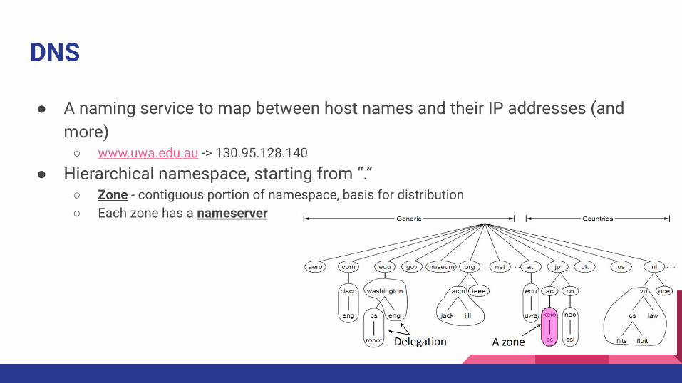
● A naming service to map between host names and their IP addresses (and more)
○ www.uwa.edu.au -> 130.95.128.140● Hierarchical namespace, starting from “.”
○ Zone - contiguous portion of namespace, basis for distribution○ Each zone has a nameserver

DNS Queries
● Iterative vs. Recursive Queries○ Recursive query offloads client burden, can cache results○ Iterative query run on high load servers
DNS Issues
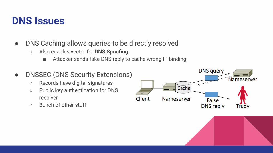
● DNS Caching allows queries to be directly resolved○ Also enables vector for DNS Spoofing
■ Attacker sends fake DNS reply to cache wrong IP binding
● DNSSEC (DNS Security Extensions)○ Records have digital signatures○ Public key authentication for DNS
resolver○ Bunch of other stuff

HTTP
Steps to fetch a web HTTP:
● Resolve the server IP● Setup TCP connection (port 80)● Send/Receive HTTP request over
TCP● Teardown TCP connection
Steps to fetch a web HTTPS:
● Resolve the server IP● Setup TCP connection (port 443)● SSL/TLS negotiation and key
exchange● Send Encrypted messages● Teardown connection
How to decrease Page Load Time (PLT)?● Parallel connections and persistent connections● HTTP caching and proxies● Move content closer to client (CDNs)

CDNs
● Content Delivery Networks○ It’s just a cache
● Place popular content near clients● Use DNS to place replicas across the Internet for use by all nearby clients

Security● Crypto
● TLS
● VPNs
● TOR
● DoS
45

Encryption
Two main kinds of encryption:1. Symmetric key encryption, e.g. AES
○ Alice and Bob share secret keyto encrypt/decrypt
2. Public key encryption, e.g. RSA○ Alice and Bob have public/private key pairs○ Alice encrypts with Bob’s public key, only Bob
can then decrypt with their own private key
● MAC (Message Authentication Code) can be included toensure ciphertext’s integrity
○ i.e. what if an attacker randomly flipped bits in the ciphertext?

Encryption, Tradeoffs
Combining the two:- Use public key encryption to send a private key- Then use that shared private key for symmetric encryption
- Key is called a session key

SSL/TLS
● Goal: provide secure transport, client must securely connect to servers not used before
○ Uses public key authentication - but how does a client get a public key from unknown server?○ With certificates
● Certificate - binding of public key to identity/domain○ Idea, public keys can be distributed when signed by a party you trust

Public Key Infrastructure
● Adds hierarchy to certificates to let parties (Certificate Authorities) issue
● If we have public key of Root, and trust in servers on path,client can verify public key of website ABC

TLS Handshake

Virtual Private Networks (VPNs)
● Connects private networks over the public internet using tunnelling○ Tunnel endpoints encapsulate IP packets (“IP in IP”) to send across tunnel○ Uses IPSEC to secure tunnel

Tor: “The Onion Router”
Basic idea:1. Many volunteers act as routers in the overlay2. Generate circuit of routers that will send packet3. Encrypt the packet in layers for each router4. Send the packet5. Each router receives, decrypts their layer,
and forwards based on new info6. Routers maintain state about circuit to
route stuff back to sender● But again, only know the next hop

Resource Attacks
● Distributed Denial-of-Service (DDOS)○ Attack on network availability○ Flooding a host with many packets to interfere
with its IP connectivity○ Attackers can falsify their IP address, or spoof
source IP addresses in replies■ Not all ISPs do ingress filtering
● Botnet○ Provides many attackers from compromised hosts

Physical Layer ● Media Types● Coding and Modulation
schemes● Fundamental limits

Physical Layer
● Physical layer - translate analog signal on wires into digital bits
● Media types○ Wired - twisted pair, coaxial○ Fiber - long, thin strands of glass○ Wireless - broadcasted signal
■ Potentially many receivers■ Nearby signals interfere at a receiver
Wireless signal interference

Coding and Modulation
● How can we send information across a link?● Coding - directly on a wire
○ Simplest scheme - Non-Return to Zero, high voltage represents 1, low voltage represents 0○ Better schemes account for clock recovery - 4B/5B coding, Manchester encoding, etc.
● Modulation - carrying RF signals by modulating a carrier signal

Fundamental Limits
● Key Channel Properties - B: Bandwidth (hertz), S: Signal strength, N: Noise
● Nyquist Limit○ Maximum symbol rate is 2B○ With V signal levels, ignoring noise,
max bit rate R = 2B log_2(V) bits/sec
● Shannon Capacity○ Signal-to-Noise ratio (S/N) determines number of distinguishable voltage levels○ Max carrying rate C = B log_2(1 + S/N) bits/sec
■ Max rate at transmitting without loss over a random channel■ Increasing signal power gives diminishing returns■ Increasing bandwidth increases capacity linearly
○ How does Shannon Capacity affect wired/wireless designs?

Fundamental Limits
● Bandwidth-Delay Product○ Describes current amount of data in transit○ BD = R x D, measures in bits, or in messages

Link Layer ● Framing● Error detection, correction● Multiple Access● Switching

Link Layer, Framing
● Link layer - transfer frames over one or more connected links
● Framing - how do we interpret a stream of bits as a sequence of frames?○ Fixed-size frames (motivation), wasteful for small payloads○ Byte count (motivation), store length of frame as header for frame○ Byte stuffing/bit stuffing, encode flag at byte/bit level at start and end of frame

Error Detection, Correction
● Noise may flip some received bits in message
● Key idea: error detection/correction codes○ Add check bits to the message to let some errors be detected (and more required for
correction)
● Tradeoffs:○ Adding check bits -> larger bandwidth requirements○ Need modest computation to detect/correct error

Error Detection, Correction cont.
● Hamming distance of a coding - minimum error distance between any pair of codewords that cannot be detected
○ e.g. 1-dimensional parity has Hamming distance of 2, since 2 bit-flips required to get to next valid codeword
○ 1 0 0 0 | 1 -> 0 1 0 0 | 1, both pass error detection
● Error detection:○ For a coding of distance d + 1, up to d errors will always be detected
● Error correction:○ For a coding of distance 2d + 1, up to d errors can always be corrected by mapping to closest
valid keyword
● Larger messages use checksums for error detection

Error Detection, Correction cont.
● Why is error correction harder?○ Need to narrow down position of the error, but errors can also occur in the check bit○ Two-dimensional parity can correct 1-bit errors by identifying row/column with error
● With a code with a Hamming distance of at least 3,○ Single bit errors will be closest to a unique valid codeword
● Error correction:○ Needed when errors are expected○ Or no time for retransmissions○ Used in physical layer (802.11, DVB, WiMAX),
application layer (FEC)● Error detection:
○ More efficient when errors not expected○ And errors are large when they do occur○ Used with retransmission in link layer and above layers for residual errors

Multiple Access
● Multiplexing shared link usage○ Time Division Multiplexing (TDM) - users take turns on a fixed schedule○ Frequency Division Multiplexing (FDM) - users placed on different frequency bands○ Tradeoffs?
● Centralized vs. Distributed Multiple Access○ Centralized, use a “scheduler” to choose who transmits and when
■ E.g. cellular networks (tower coordinates)■ Scales well + efficient, but long setup and management
○ Distributed, have participants “figure it out” somehow■ E.g. WiFi networks■ Operates well in low load and easy setup, but hard to scale

Distributed (random) Access
● How do nodes share a single link? Who sends when?○ Aloha - just send it whenever○ CSMA (Carrier Sense Multiple Access) - listen for activity before we send○ CSMA/CD (with Collision Detection) - receiver detects collision and aborts (jams)
● CSMA “Persistence”○ Each node waits 2 * delay seconds to hear of a collision○ Problem - multiple waiting nodes will queue up, then collide
■ Ideally want N senders to send with probability 1/N■ Solution: Binary Exponential Backoff (BEB)
● 1st collision, wait 0 or 1 frame times● 2nd collision, wait from 0 to 3 times● 3rd collision, wait from 0 to 7 times ....

Wireless Complications
1. Media is infinite - can’t Carrier Sense2. Nodes (usually) can’t hear while sending - can’t Collision Detect
Hidden Terminal Problem:● A and C can’t hear each other, but collide
at B
Exposed Terminal Problem:● B and C can hear each other, but don’t
collide at A and D

MACA
● Uses short handshake instead of CSMA
● Protocol rules:1. A sender node transmits a RTS (Request-To-Send, with frame length)2. The receiver replies with a CTS (Clear-To-Send, with frame length)3. Sender transmits the frame while nodes hearing the CTS stay silent

MACA
Hidden Terminal Problem:● A and C can’t hear each other, but collide
at B
Exposed Terminal Problem:● B and C can hear each other, but don’t
collide at A and D

Switching
● Modern Ethernet uses switches instead of multiple access○ Convenience running wires to one location○ More reliable - wire cut is not a single point of failure
● Switch Forwarding○ Switch needs to find right output port for destination address○ Backward learning
■ To fill table, looks at source address of input frames■ To forward, looks up address in table or broadcasts to all ports if not found
● Issue - forwarding loops○ Solution, each switch runs distributed spanning tree algorithm○ Finds subset of links w/ no loops and reaches all switches


![CSE 461: Introduction Ben Greenstein [Intel Research] Jeremy Elson [Microsoft Research] Fall 2008.](https://static.fdocuments.us/doc/165x107/56649da95503460f94a964e8/cse-461-introduction-ben-greenstein-intel-research-jeremy-elson-microsoft.jpg)