CSDG – 230kW
42
CSDG – 230kW CUMMINS / DSHAD 230 Cummins Sales and Service Page 1 of 42
Transcript of CSDG – 230kW

CSDG – 230kW
CUMMINS / DSHAD 230
Cummins Sales and Service
Page 1 of 42
NOTICE A COPY OF THIS GENERATOR SET SUBMITTAL MUST BE RETURNED TO OUR OFFICE, APPROVED IN ITS ENTIRETY AND BEARING THE DATE OF APPROVAL, STAMP OR SIGNATURE AND TITLE OF THE APPROVING AUTHORITY, BEFORE ANY ITEM WILL BE RELEASED FOR MANUFACTURE OR SHIPMENT. WE ASSUME NO RESPONSIBILITY FOR DELAYS IN OUR FORECASTED SHIPPING SCHEDULES ON ANY ITEM ON WHICH SUBMITTAL APPROVAL IS BEYOND THIRTY (30) DAYS FROM THE SUBMISSION DATE ON THE COVER PAGE. THIS SUBMITTAL IS BASED UPON OUR INTERPRETATION OF THE PROJECT REQUIREMENTS AND/OR SPECIFICATIONS AND IS IN ACCORDANCE WITH YOUR ORDER AND PRODUCT AVAILABILITY OF FROM OUR VENDORS. PLEASE REVIEW THE ENCLOSED DATA COMPLETELY AND CAREFULLY. SHOULD ADDITIONAL INFORMATION OR CLARIFICATION BE REQUIRED PLEASE FORWARD A SUBMITTAL COPY, COMPLETE WITH YOUR NOTATIONS, TO OUR OFFICE WITHIN THIRTY (30) DAYS FOR A PROMPT RESPONSE AND/OR RESUBMITTAL. CONSIDERABLE ATTENTION IS GIVEN TO THE PREPARATION OF THIS SUBMITTAL TO ENSURE IT IS COMPLETE, CONCISE AND CORRECT AS IS POSSIBLE. PLEASE REVIEW IT CAREFULLY AND THOROUGHLY.
Page 2 of 42

Table of Contents
CSDG – 230kW
Page
Cover Letter 1
Notice Letter 2
Table of Contents 3
Bill of Materials 4
Generator Specification Sheet 5‐9
Generator Data Sheet 10‐14
Generator PowerCommand Control ‐ PCC 2100 15‐20
Generator Alternator Data Sheet 21
Prototype Test Certificate 22
Prototype Test Summary Report 23
Generator Open Unit Drawing 24
Generator Circuit Breaker Specification Sheet 25‐27
Generator Circuit Breaker Drawing 28
Generator Coolant Heater Drawing 29
Generator Enclosure and Fuel Tank Specification Sheet 30‐33
Generator Enclosure Drawing 34
Generator Fuel Tank Drawing 35‐36
Generator Battery Charger Specification Sheet 37‐39
Generator ‐ Accessories Wiring Diagram 40
Generator Warranty Statement ‐ Base 41‐42
Page 3 of 42

Bill of Materials
ITEM NUMBER DESCRIPTION Quantity
1 Commercial Diesel Generator Set, 230kW Standby 60Hz 1
Genset-Diesel,60Hz,230kW
U.S. EPA, Stationary Emergency Application
Duty Rating - Standby Power (ESP)
Listing - UL 2200
Exciter / Regulator - Permanent Magnet Generator, 3 Phase Sensor
Voltage - 277 / 480, 3 Phase, Wye, 4 Wire
Alternator - 60Hz, 12 Lead, Limited Range, 125 C
Emissions Certification, EPA, Tier 3, NSPS CI Stationary Emergency
Steel Weather Protective Enclosure, with Exhaust System
Skidbase - Housing Ready
Fuel Tank - Dual Wall Sub Base, 24 Hour Capacity
Listing, ULC - S601 - 07
PowerCommand 2100 Generator Controller
Backlit Digital Control Display
Control Display Language - English
Circuit Breaker or EB or TB - Left Only
Circuit Breaker - 400A, Left, 3P, 600 / 690V, SS RMS, 80%, UL / IEC
Engine Governor - Electronic, Isochronous
Switch - Low Fuel Level, Sub Base
Switch - Annunciator, Liquid In Rupture Basin
Engine Cooling - Radiator, High Ambient Air Temperature, Ship Fitted
Warning - Low Coolant Level
Extension - Coolant Drain
Coolant Heater - 120 Volt AC, Single Phase
Genset Warranty - 2 Years Base
Battery Rack
Extension - Oil Drain
Battery Charger-10Amp, 120/208/240VAC, 12/24V, 50/60Hz 1
Page 4 of 42

power.cummins.com ©2017 Cummins Inc. | S-1587 (10/17)
Specification sheet
Diesel generator set QSL9-G2 series engine 175 kW - 230 kW Standby
Description
Cummins® commercial generator sets are fully integrated power generation systems providing optimum performance, reliability and versatility for stationary Standby and Prime Power applications.
Control system - The PowerCommand® electronic control is standard equipment and provides total genset system integration including automatic remote starting/stopping, precise frequency and voltage regulation, alarm and status message display, AmpSentry™ protection, output metering, auto-shutdown at fault detection and NFPA 110 Level 1 compliance.
Cooling system - Standard integral set-mounted radiator system, designed and tested for rated ambient temperatures, simplifies facility design requirements for rejected heat.
Enclosures - Optional weather protective and sound attenuated enclosures are available.
Fuel tanks - Dual wall sub-base fuel tanks are also available.
NFPA - The genset accepts full rated load in a single step in accordance with NFPA 110 for Level 1 systems.
Warranty and service - Backed by a comprehensive warranty and worldwide distributor network.
Features
Cummins heavy-duty engine - Rugged 4-cycle, industrial diesel delivers reliable power, low emissions and fast response to load changes.
Alternator - Several alternator sizes offer selectable motor starting capability with low reactance 2/3 pitch windings, low waveform distortion with non-linear loads and fault clearing short-circuit capability.
Standby rating Prime rating Continuous rating Data sheets
Model 60 Hz kW (kVA)
50 Hz kW (kVA)
60 Hz kW (kVA)
50 Hz kW (kVA)
60 Hz kW (kVA)
50 Hz kW (kVA) 60 Hz 50 Hz
DSHAB 175 (219) 160 (200) D-3451
DSHAC 200 (250) 180 (225) D-3452
DSHAD 230 (288) 209 (261) D-3453
Page 5 of 42
hd985
Highlight
hd985
Highlight
hd985
Highlight
hd985
Highlight

power.cummins.com ©2017 Cummins Inc. | S-1587 (10/17)
Generator set specifications Governor regulation class ISO 8528 Part 1 Class G3
Voltage regulation, no load to full load ± 0.5%
Random voltage variation ± 0.5%
Frequency regulation Isochronous
Random frequency variation ± 0.25%
Radio frequency emissions compliance Meets requirements of most industrial and commercial applications.
Engine specifications Bore 114.0 mm (4.49 in)
Stroke 145 mm (5.69 in)
Displacement 8.9 L (543 in3)
Configuration Cast iron, in-line 6 cylinder
Battery capacity 1500 amps minimum at ambient temperature of -18 °C (0 °F)
Battery charging alternator 100 amps
Starting voltage 12 volt, negative ground
Fuel system Direct injection: number 2 diesel fuel, fuel filter, automatic electric fuel shutoff
Fuel filter Single element, 10 micron filtration, spin-on fuel filter with water separator
Air cleaner type Dry replaceable element
Lube oil filter type(s) Spin-on, full flow
Standard cooling system High ambient radiator
Alternator specifications Design Brushless, 4 pole, drip proof revolving field
Stator 2/3 pitch
Rotor Single bearing, flexible discs
Insulation system Class H
Standard temperature rise 150 °C Standby at 40 °C ambient
Exciter type Torque match (shunt)
Phase rotation A (U), B (V), C (W)
Alternator cooling Direct drive centrifugal blower
AC waveform Total Harmonic Distortion (THDV) < 5% no load to full linear load, < 3% for any single harmonic
Telephone Influence Factor (TIF) < 50 per NEMA MG1-22.43
Telephone Harmonic Factor (THF) < 3
Available voltages Three phase reconnectable
Single phase non-reconnectable
Three phase non-reconnectable
120/208 240/416
120/240 254/440
127/220
277/480
139/240
120/241 220/380 347/600
Note: Consult factory for other voltages.
Page 6 of 42
hd985
Highlight

power.cummins.com ©2017 Cummins Inc. | S-1587 (10/17)
Generator set options and accessories Engine
120/240 V 1500 W coolant heater
120/240 V 150 W lube oil heater Heavy duty air cleaner Engine oil temperature
Fuel system
12 hour sub-base tank (dual wall)
24 hour sub-base tank (dual wall)
473 L (125 gal) sub-base tank (single wall)
Alternator 105 °C rise 125 °C rise 120/240 V 100 W anti-condensation heater
PMG excitation Single phase
Exhaust system Genset mounted muffler Heavy duty exhaust elbow Slip on exhaust connection
Generator set AC entrance box Battery Battery charger Enclosure: aluminum, steel, weather protective or sound attenuated
Export box packaging UL 2200 Listed Main line circuit breaker PowerCommand Network Communications module (NCM)
Remote annunciator panel Spring isolators 2 year Prime power warranty 2 year Standby power warranty 5 year Basic power warranty
Note: Some options may not be available on all models - consult factory for availability.
Page 7 of 42
hd985
Highlight
hd985
Highlight
hd985
Highlight
hd985
Highlight
hd985
Highlight
hd985
Highlight
hd985
Highlight
hd985
Highlight

power.cummins.com ©2017 Cummins Inc. | S-1587 (10/17)
Control system PCC 2100
PowerCommand control is an integrated generator set control system providing governing, voltage regulation, engine protection and operator interface functions. Major features include:
Integral AmpSentry™ Protective Relay providing a full range of alternator protection functions that are matched to the alternator provided.
Battery monitoring and testing features and smart starting control system.
Three phase sensing, full wave rectified voltage regulation system, with a PWM output for stable operation with all load types.
Standard PCCNet™ and optional Echelon® LONWORKS® network interface.
Control suitable for operation in ambient temperatures from -40 °C to +70 °C (-40 °F to +158 °F) and altitudes to 5000 meters (13,000 feet).
Prototype tested; UL, CSA, and CE compliant.
InPower™ PC-based service tool available for detailed diagnostics.
Operator/display panel Off/manual/auto mode switch
Manual run/stop switch
Panel lamp test switch
Emergency stop switch
Alpha-numeric display with pushbutton access for viewing engine and alternator data and providing setup, controls and adjustments
LED lamps indicating genset running, not in auto, common warning, common shutdown
Configurable LED lamps (5)
Configurable for local language
Engine protection Overspeed shut down
Low oil pressure warning and shut down
High coolant temperature warning and shut down
High oil temperature warning (some models)
Low coolant level warning or shut down
Low coolant temperature warning
High and low battery voltage warning
Weak battery warning
Dead battery shut down
Fail to start (overcrank) shut down
Fail to crank shut down
Redundant start disconnect
Cranking lockout
Sensor failure indication
Engine data DC voltage
Lube oil pressure
Coolant temperature
Lube oil temperature (some models)
Engine speed
AmpSentry AC protection Over current and short-circuit shut down
Over current warning
Single and three phase fault regulation
Over and under voltage shut down
Over and under frequency shut down
Overload warning with alarm contact
Reverse power and reverse Var shut down
Excitation fault
Alternator data Line-to-Line and Line-to-Neutral AC volts
Three phase AC current
Frequency
Total and individual phase power factor, kW and kVA
Other data Genset model data
Start attempts, starts, running hours
kW hours (total and since reset)
Fault history
Load profile (hours less than 30% and hours more than 90% load)
System data display (optional with network and other PowerCommand gensets or transfer switches)
Governing Digital electronic isochronous governor
Temperature dynamic governing
Smart idle speed mode
Glow plug control (some models)
Voltage regulation Digital PWM electronic voltage regulation
Three phase Line-to-Neutral sensing
Suitable for PMG or shunt excitation
Single and three phase fault regulation
Configurable torque matching
Control functions Data logging on faults
Fault simulation (requires InPower)
Time delay start and cooldown
Cycle cranking
PCCNet interface
Configurable customer inputs (4)
Configurable customer outputs (4)
Configurable network inputs (8) and outputs (16) (with optional network)
Remote emergency stop
Options LED bargraph AC data display
Thermostatically controlled space heater
Key-type mode switch
Ground fault module
Auxiliary relays (3)
Echelon LONWORKS interface
Modion Gateway to convert to Modbus (loose)
PowerCommand iWatch web server for remote monitoring and alarm notification (loose)
Digital input and output module(s) (loose)
Remote annunciator (loose)
For further detail see document S-1409.
Page 8 of 42

For more information contact your local Cummins distributor or visit power.cummins.com
©2017 Cummins Inc. All rights reserved. Cummins is a registered trademark of Cummins Inc. PowerCommand, AmpSentry, InPower and “Our energy working for you.” are trademarks of Cummins Inc. Other company, product, or service names may be trademarks or service marks of others. Specifications are subject to change without notice. S-1587 (10/17)
Emergency Standby Power (ESP):
Applicable for supplying power to varying electrical load for the duration of power interruption of a reliable utility source. Emergency Standby Power (ESP) is in accordance with ISO 8528. Fuel Stop power in accordance with ISO 3046, AS 2789, DIN 6271 and BS 5514. Limited-Time Running Power (LTP):
Applicable for supplying power to a constant electrical load for limited hours. Limited Time Running Power (LTP) is in accordance with ISO 8528. Prime Power (PRP):
Applicable for supplying power to varying electrical load for unlimited hours. Prime Power (PRP) is in accordance with ISO 8528. Ten percent overload capability is available in accordance with ISO 3046, AS 2789, DIN 6271 and BS 5514. Base Load (Continuous) Power (COP):
Applicable for supplying power continuously to a constant electrical load for unlimited hours. Continuous Power (COP) in accordance with ISO 8528, ISO 3046, AS 2789, DIN 6271 and BS 5514.
This outline drawing is for reference only. See respective model data sheet for specific model outline drawing number.
Do not use for installation design
Model
Dim “A” mm (in.)
Dim “B” mm (in.)
Dim “C” mm (in.)
Set weight* dry kg (lbs)
Set weight* wet kg (lbs)
DSHAB 2662 (104.8) 1016 (40.0) 1361 (53.6) 1561 (3442)
DSHAC 2662 (104.8) 1016 (40.0) 1361 (53.6) 1561 (3442)
DSHAD 2667 (105.0) 1016 (40.0) 1372 (54.0) 1469 (3238) *Weights represent a set with standard features. See outline drawings for weights of other configurations.
Codes and standards Codes or standards compliance may not be available with all model configurations – consult factory for availability.
This generator set is designed in facilities certified to ISO 9001 and manufactured in facilities certified to ISO 9001 or ISO 9002.
The PowerCommand control is Listed to UL 508 - Category NITW7 for U.S. and Canadian usage.
The Prototype Test Support (PTS) program verifies the performance integrity of the generator set design. Cummins products bearing the PTS symbol meet the prototype test requirements of NFPA 110 for Level 1 systems.
Engine certified to Stationary Emergency U.S. EPA New Source Performance Standards,40 CFR 60 subpart IIII Tier 3 exhaust emission levels. U.S. applications must be applied per this EPA regulation.
All low voltage models are CSA certified to product class 4215-01.
The generator set package is available certified for seismic application in accordance with the following International Building Code: IBC2000, IBC2003, IBC2006, IBC2009 and IBC2012.
Warning: Back feed to a utility system can cause electrocution and/or property damage. Do not connect to any building’s electrical system except through an approved device or after building main switch is open.
Page 9 of 42
hd985
Highlight
hd985
Highlight
hd985
Highlight
hd985
Callout
see below drawings for overall shipping weight and dimensions
power.cummins.com ©2019 Cummins Inc. | PDD-3453 (10/19)
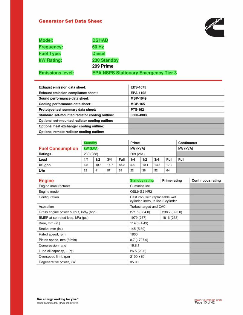
Model: DSHAD Frequency: 60 Hz Fuel Type: Diesel
kW Rating: 230 Standby 209 Prime
Emissions level: EPA NSPS Stationary Emergency Tier 3
Exhaust emission data sheet: EDS-1075
Exhaust emission compliance sheet: EPA-1102
Sound performance data sheet: MSP-1049
Cooling performance data sheet: MCP-165
Prototype test summary data sheet: PTS-162
Standard set-mounted radiator cooling outline: 0500-4303
Optional set-mounted radiator cooling outline:
Optional heat exchanger cooling outline:
Optional remote radiator cooling outline:
Fuel Consumption
Standby Prime Continuous
kW (kVA) kW (kVA) kW (kVA)
Ratings 230 (288) 209 (261)
Load 1/4 1/2 3/4 Full 1/4 1/2 3/4 Full Full
US gph 6.2 10.8 14.7 18.2 5.8 10.1 13.8 17.0
L/hr 23 41 57 69 22 38 52 64
Engine Standby rating Prime rating Continuous rating
Engine manufacturer Cummins Inc.
Engine model QSL9-G2 NR3
Configuration Cast iron, with replaceable wet cylinder liners, in-line 6 cylinder
Aspiration Turbocharged and CAC
Gross engine power output, kWm (bhp) 271.5 (364.0) 238.7 (320.0)
BMEP at set rated load, kPa (psi) 1979 (287) 1816 (263)
Bore, mm (in.) 114.0 (4.49)
Stroke, mm (in.) 145 (5.69)
Rated speed, rpm 1800
Piston speed, m/s (ft/min) 8.7 (1707.0)
Compression ratio 16.8:1
Lube oil capacity, L (qt) 26.5 (28.0)
Overspeed limit, rpm 2100 ± 50
Regenerative power, kW 35.00
Page 10 of 42
hd985
Highlight
hd985
Highlight
hd985
Highlight
hd985
Highlight
hd985
Highlight

power.cummins.com ©2019 Cummins Inc. | PDD-3453 (10/19)
Fuel Flow Standby rating Prime rating Continuous rating
Fuel flow at rated load, L/hr (US gph) 162.8 (43.0)
Maximum inlet restriction, mm Hg (in Hg) 152.4 (6.0)
Maximum return restriction, mm Hg (in Hg) 254.0 (10.0)
Air
Combustion air, m3/min (scfm) 20.9 (739.0) 20.8 (733.0)
Maximum air cleaner restriction with clean filter, kPa (in H2O)
3.7 (15)
Alternator cooling air, m3/min (cfm) 41.3 (1460.0)
Exhaust
Exhaust flow at set rated load, m3/min (cfm) 33.3 (1176) 31.0 (1157)
Exhaust temperature, °C (°F) 600 (1110.0) 572 (1063.0)
Maximum back pressure, kPa (in H2O) 10.2 (41.0)
Standard Set-Mounted Radiator Cooling (Non-Seismic)
Ambient design, °C (°F) 52 (126) 48 (118)
Fan load, kWm (HP) 16.4 (22)
Coolant capacity (with radiator), L (US gal) 29.5 (7.8)
Cooling system air flow, m3/min (scfm) 248 (8769)
Total heat rejection, MJ/min (Btu/min) 7.8 (7374) 7.6 (7222)
Maximum cooling air flow static restriction, kPa (in H2O) 0.12 (0.5)
Optional Set-Mounted Radiator Cooling Ambient design, °C (°F)
Fan load, kWm (HP)
Coolant capacity (with radiator), L (US gal)
Cooling system air flow, m3/min (scfm)
Total heat rejection, MJ/min (Btu/min)
Maximum cooling air flow static restriction, kPa (in H2O)
Page 11 of 42
hd985
Highlight

power.cummins.com ©2019 Cummins Inc. | PDD-3453 (10/19)
Optional Heat Exchanger Cooling Standby rating Prime rating Continuous rating
Set coolant capacity, L (US gal)
Heat rejected, jacket water circuit, MJ/min (Btu/min)
Heat rejected, aftercooler circuit, MJ/min (Btu/min)
Heat rejected, fuel circuit, MJ/min (Btu/min)
Total heat radiated to room, MJ/min (Btu/min)
Maximum raw water pressure, jacket water circuit, kPa (psi)
Maximum raw water pressure, aftercooler circuit, kPa (psi)
Maximum raw water pressure, fuel circuit, kPa (psi)
Maximum raw water flow, jacket water circuit, L/min (US gal/min)
Maximum raw water flow, aftercooler circuit, L/min (US gal/min)
Maximum raw water flow, fuel circuit, L/min (US gal/min)
Minimum raw water flow at 27 °C (80 °F) inlet temp, jacket water circuit, L/min (US gal/min)
Minimum raw water flow at 27 °C (80 °F) inlet temp, aftercooler circuit, L/min (US gal/min)
Minimum raw water flow at 27 °C (80 °F) inlet temp, fuel circuit, L/min (US gal/min)
Raw water delta P at min flow, jacket water circuit, kPa (psi)
Raw water delta P at min flow, aftercooler circuit, kPa (psi)
Raw water delta P at min flow, fuel circuit, kPa (psi)
Maximum jacket water outlet temp, °C (°F)
Maximum aftercooler inlet temp, °C (°F)
Maximum aftercooler inlet temp at 25 °C (77 °F) ambient, °C (°F)
Optional Remote Radiator Cooling1
Set coolant capacity, L (US gal)
Max flow rate at max friction head, jacket water circuit, L/min (US gal/min)
Max flow rate at max friction head, aftercooler circuit, L/min (US gal/min)
Heat rejected, jacket water circuit, MJ/min (Btu/min)
Heat rejected, aftercooler circuit, MJ/min (Btu/min)
Heat rejected, fuel circuit, MJ/min (Btu/min)
Total heat radiated to room, MJ/min (Btu/min)
Maximum friction head, jacket water circuit, kPa (psi)
Maximum friction head, aftercooler circuit, kPa (psi)
Maximum static head, jacket water circuit, m (ft)
Maximum static head, aftercooler circuit, m (ft)
Maximum jacket water outlet temp, °C (°F)
Maximum aftercooler inlet temp at 25 °C (77 °F) ambient, °C (°F)
Maximum aftercooler inlet temp, °C (°F)
Maximum fuel flow, L/hr (US gph)
Maximum fuel return line restriction, kPa (in Hg)
Page 12 of 42

power.cummins.com ©2019 Cummins Inc. | PDD-3453 (10/19)
Weights2
Unit dry weight kgs (lbs)
Unit wet weight kgs (lbs) 1561 (3442)
Notes: 1 For non-standard remote installations contact your local Cummins representative. 2 Weights represent a set with standard features. See outline drawing for weights of other configurations.
Derating Factors
Standby Engine power available up to 1100 m (3600 ft) at ambient temperature up to 40 °C (104 °F). Consult your Cummins distributor for temperature and ambient requirements outside these parameters.
Prime Engine power available up to 850 m (2800 ft) at ambient temperature up to 40 °C (104 °F). Consult your Cummins distributor for temperature and ambient requirements outside these parameters.
Continuous
Ratings Definitions Emergency Standby Power (ESP):
Limited-Time Running Power (LTP):
Prime Power (PRP): Base Load (Continuous) Power (COP):
Applicable for supplying power to varying electrical load for the duration of power interruption of a reliable utility source. Emergency Standby Power (ESP) is in accordance with ISO 8528. Fuel stop power in accordance with ISO 3046, AS 2789, DIN 6271 and BS 5514.
Applicable for supplying power to a constant electrical load for limited hours. Limited-Time Running Power (LTP) is in accordance with ISO 8528.
Applicable for supplying power to varying electrical load for unlimited hours. Prime Power (PRP) is in accordance with ISO 8528. Ten percent overload capability is available in accordance with ISO 3046, AS 2789, DIN 6271 and BS 5514.
Applicable for supplying power continuously to a constant electrical load for unlimited hours. Continuous Power (COP) is in accordance with ISO 8528, ISO 3046, AS 2789, DIN 6271 and BS 5514. No sustained overload capability is available at this rating.
Alternator Data
Three phase table1 125 °C 125 °C 150 °C 150 °C
Feature code B414 B246 B268 B419
Alternator data sheet number 213 212 212 212
Voltage ranges
120/208 thru 139/240 240/416 thru 277/480
277/480
120/208 thru 139/240 240/416 thru 277/480
347/600
Surge kW 233 233 233 233
Motor Starting kVA (at 90% sustained voltage)
Shunt 770 212 770 770
PMG 920 920 920 920
Full load current - amps at Standby rating
120/208 799
120/240 629
139/240 629
220/380 399
277/480 346
347/600 277
Page 13 of 42
hd985
Callout
see below drawings for overall shipping weight and dimensions
hd985
Highlight
hd985
Highlight
hd985
Highlight
hd985
Highlight

For more information contact your local Cummins distributor or visit power.cummins.com
©2019 Cummins Inc. All rights reserved. Cummins is a registered trademark of Cummins Inc. PowerCommand, AmpSentry, InPower and “Our energy working for you.” are trademarks of Cummins Inc. Other company, product, or service names may be trademarks or service marks of others. Specifications are subject to change without notice. PDD-3453 (10/19)
Alternator Data (continued)
Single phase table1 125 °C
Feature code B414
Alternator data sheet number 213
Voltage ranges 120/2402
Surge kW 233
Motor Starting kVA (at 90% sustained voltage)
Shunt 420
PMG 500
Full load current - amps at Standby rating
120/2402 639
Notes: 1 Single phase power can be taken from a three phase generator set at up to 2/3 set rated 3-phase kW at 1.0 power factor. 2 The broad range alternators can supply single phase output up to 2/3 set rated 3-phase kW at 1.0 power factor.
Formulas for Calculating Full Load Currents:
Three phase output Single phase output
kW x 1000 kW x SinglePhaseFactor x 1000
Voltage x 1.73 x 0.8 Voltage
Warning: Back feed to a utility system can cause electrocution and/or property damage. Do not connect to any building’s electrical system except through an approved device or after building main switch is open.
Page 14 of 42

power.cummins.com ©2019 Cummins Inc. | PDS-1409 | PD00000150 | (09/19)
Specification Sheet
PowerCommand® 2100 Digital Generator Set Control
Description Features
The PowerCommand 2100 control is a microprocessor-based generator set monitoring, metering and control system. The control provides an operator interface to the genset, digital voltage regulation, digital governing and generator set protective functions. The integration of all the functions into a single control system provides enhanced reliability and performance compared to conventional control systems.
The PowerCommand control is designed for mounting on the generator set and is suitable for use on a wide range of generator sets in non-paralleling applications. The PowerCommand control will directly read AC voltages up to 600 VAC and can be configured for any frequency, voltage and power connection configuration from 120 to 600 VAC.
The control offers a wide range of standard control and digital display features so custom control configurations are not needed to meet application specifications. System reliability is not compromised by use of untested special components.
Power for PowerCommand control is usually derived from the generator set starting batteries. It functions without degradation in performance over a voltage range from 8 VDC to 35 VDC.
Digital engine speed governing controls - Provide isochronous frequency regulation (optional on some genset models).
Digital voltage regulation - 3-phase sensing.
AmpSentry™ protective relay - UL Listed, true alternator over current protection.
Analog and digital AC output metering.
Battery monitoring system - Senses and warns against a weak battery condition.
Digital alarm and status message display.
Generator set monitoring - Displays status of all critical engine and alternator functions.
Smart starting control system - Temperature dynamic integrated fuel ramping to limit black smoke and frequency overshoot, in addition to optimized cold weather starting.
PCCNet interface - A proprietary RS485 network interface to allow easy plug and play interface to remote annunciators, relay modules for extensible I/O and other devices.
Advanced serviceability - Interfaces to InPower™, a PC-based software service tool. A version of InPower is available for customer use.
PowerCommand LonWorks® network (optional) - Provides interfaces to external devices through a twisted pair wire and other media.
Certifications - Suitable for use on generator sets that are designed, manufactured, tested, and certified to relevant UL, NFPA, ISO, IEC, and CSA standards.
Warranty and service - Backed by a comprehensive warranty and worldwide distributor service network.
Page 15 of 42
hd985
Highlight

power.cummins.com ©2019 Cummins Inc. | PDS-1409 | PD00000150 | (09/19)
Operator Panel Lamps (5) are configurable for color and function. These lamps are configured with InPower for any condition monitored by the control. Default configuration for these lamps include the following functions:
Low oil pressure warning
High engine temperature warning
Low oil pressure shutdown
Over speed shutdown
Fail to start
Analog AC Metering Panel (Optional)
The PowerCommand control can be equipped with an analog AC metering panel that simultaneously displays 3-phase Line-to-Line AC volts and current, kW, power factor, and frequency. The meter panel is composed of a series of LEDs configured in bar graphs for each function. The LEDs are color coded, with green indicating normal range values, amber for warning levels and red for shutdown conditions. Scales for each function are in % of nominal rated values. Resolution is 1% for values close to nominal and increases at values far from nominal.
Alphanumeric Display Panel
The PowerCommand control is provided with an alphanumeric display capable of displaying 2 lines of data with approximately 20 characters per line. The display is accompanied by a set of six tactile-feel membrane switches that are used by the operator to navigate through control menus and to make control adjustments. (There are no rotary potentiometers in the control. All adjustments are made via the display panel or InPower). Display is configurable for multiple languages. It is configurable for units of measurement. All data on the control can be viewed by scrolling through screens with the navigation keys. The control displays all active fault conditions with the latest displayed first. Active and inactive faults are displayed. The display panel includes a screen-saver timer that will turn off the display after 30 minutes of inactivity. Touching any key will turn the screen back on. Generator set hardware data - Generator set rating in kVA, complete generator set model number and provisions for generator set serial number, engine model and serial number, and alternator model and serial number. The control stores the part number of the control and the software version present in the control. This information is read using InPower.
The operator panel provides the user with a complete package of easy to view and use information. Connections to the operator panel are locking plug interfaces for reliable, vibration-resistant interconnection to the generator set wiring harness.
Control Switches and Functions
Off/manual/auto mode control switch - The not in auto lamp will flash when the control is in the manual or off mode. In the auto mode, the generator set can be started with a start signal from a remote device, such as an automatic transfer switch. Manual run/stop control switch - When the mode control switch is in the manual position and the manual/run/stop switch is pressed, the generator set will start, bypassing time delay start. The control is configurable to include an idle period on manual start. If the generator set is running in the manual mode, pressing the run/stop switch will cause the generator set to shut down after a cool down at idle period. Panel lamp/lamp test control switch - Depressing the panel lamp switch will cause the panel illumination to operate for approximately 10 minutes. Pressing and holding the switch will sequentially illuminate all LED lamps on the panel to confirm proper operation of these components. Fault acknowledge/reset switch - The control includes a fault acknowledge function to allow the operator to reset the fault condition. If the fault condition is not corrected, the fault will reappear, but will not be logged as a separate event. Multiple faults can be logged and displayed at one time. Emergency stop control switch - Pressing the emergency stop switch will cause the generator set to immediately shut down. The generator set is prevented from running or cranking with the switch pressed in. Operator adjustments - The control includes provisions for many set up and adjustment functions via raise/lower switches on the operator panel. Functions that can be adjusted by the operator include:
Time delay start (0-300 seconds)
Time delay stop (0-600 seconds)
Alternator voltage (±5%)
Alternator frequency (±5%)
Indicating Lamps
The operator panel includes a series of LED indicating lamps to allow the operator to view the general status of the generator set. Functions displayed include: Green lamps to indicate generator set running (operating at rated voltage and frequency); remote start signal received. Red (flashing) lamp to indicate not-in-auto mode and a red lamp to indicate common shutdown. Amber lamp for common warning.
Page 16 of 42

power.cummins.com ©2019 Cummins Inc. | PDS-1409 | PD00000150 | (09/19)
Data logs - Number of start attempts and number of start attempts since reset. Number of times generator set has run and duration of generator set running time. Generator set kWh produced. The control also stores number of start attempts, operating hours and kW hours since each has been reset. This data is read with InPower. Adjustment history - Provides a record of adjustment and setting changes made on the control and identifies whether adjustment was made via the operator panel or with a service tool. If a service tool is used, the control provides a record of the serial number of the tool used. This information is read with InPower. Fault history - Provides a record of the most recent fault conditions with time stamp, along with the number of times each fault has occurred. Up to 20 events are stored in the control non-volatile memory.
Load profile data - Control logs data indicating the operating hours at percent of rated kW load in 10% increments. The data is presented on the operator panel based on total operating hours on the generator set based on number of hours under 30% load and number of hours at more than 90% of rated. InPower can be used to read data in detail (10% increments). Generator set output voltage - All phases, Line-to-Line and Line-to-Neutral, accuracy 1%. Data for all phases is displayed simultaneously to allow viewing of voltage balance. Generator set output current - All phases, accuracy 1%. Data for all phases is displayed simultaneously to allow viewing of load balance. Generator set output frequency. Generator set power output - PowerCommand displays generator set kW and kVA output (average and individual phase and direction of flow), and power factor with leading/lagging indication. Accuracy 5%. Generator set kWh power output - Displays total kilowatt-hours produced by the generator set and total produced since last reset, with time stamp of time of last reset. Generator set control temperature. Engine starting battery voltage. Engine lube oil pressure. Engine coolant temperature. Engine lube oil temperature (option on some genset models). System data display - The generator set will exchange data with Cummins transfer switches utilizing PowerCommand transfer controls and other generator sets using the PowerCommand 2100 control that are located on the same site and interconnected using a PowerCommand network. Information displayed from each transfer switch in the system includes: transfer switch name (assigned by customer at site), kW load (when fitted with load monitoring equipment), sources available, source connected and if any alarm conditions are present on the switch. Genset data includes genset name, kW load, status and name of any alarm conditions that are present.
Service adjustments - The operator panel includes provisions for adjustment and set up of all control functions in the generator set. The operator panel includes an access code that is used to protect the control from unauthorized service level adjustments.
Internal Control Functions
Engine Control
Remote start mode - PowerCommand accepts a ground signal from remote devices or a network signal to automatically start the generator set and immediately accelerate to rated speed and voltage. PowerCommand includes a smart starting system that is designed to quickly start the engine, minimize black smoke, minimize voltage and frequency overshoot, and oscillations on starting. The control system does this by careful control of the engine fuel system and alternator excitation system. The control can incorporate a time delay start and a warmup period at idle speed. See Engine governing for details. Sleep mode - PowerCommand can be configured to include a sleep mode. When enabled, and when the mode select switch is in the off position, the control will revert to a low power consumption mode until a control switch on the operator panel is operated (reset, panel lamp, manual run or emergency stop). Data logging - The control maintains a record of manual control operations, warning and shutdown conditions, and other events. The control also stores critical engine and alternator data before and after a fault occurs, for use by InPower and the technician in evaluating the root causes for the fault condition. Fault simulation mode - PowerCommand, in conjunction with InPower software, will accept commands to allow a technician to verify the proper operation of all protective functions of the control by simulating failure modes or by forcing the control to operate outside of its normal operating ranges. Engine starting - The control system automatically controls the engine starter and provides proper engine fueling and alternator control to provide fast and efficient starting. Cycle cranking - Configurable for number of starting cycles (1 to 7) and duration of crank and rest periods. Control includes starter protection algorithms to prevent the operator from specifying a starting sequence that might be damaging. Time delay start and stop (cool down) - Configurable for time delay of 0-300 seconds prior to starting after receiving a remote start signal; and for time delay of 0-600 seconds prior to ramp-to-idle or shutdown after signal to stop in normal operation modes. Default for both time delay periods is 0 seconds.
Engine Governing
The PowerCommand control includes integrated digital governing capability to directly drive an engine fuel control valve. Features of the governing system (when enabled) include: Isochronous governing - Controls engine speed within ±0.25% for any steady state load from no load to full load. Frequency drift will not exceed ±0.5% for a 33 °C (60 °F) change in ambient temperature over an 8 hour period. Temperature dynamics - Modifies the engine fuel system (governing) control parameters as a function of engine temperature. Allows engine to be more responsive when warm and more stable when operating at lower temperature levels.
Page 17 of 42

power.cummins.com ©2019 Cummins Inc. | PDS-1409 | PD00000150 | (09/19)
Engine Governing (Continued)
Smart idle mode - Engine governing can be regulated at an idle speed for a programmed period on automatic stop of the engine or in manual mode. In an automatic mode, the control will bypass the idle period if the engine is at a low load level for sufficient duration for cool down. During idle mode engine protective functions are adjusted for the lower engine speed, and alternator function and protections are disabled. Idle speed can be initiated by the operator when the generator set is running in the manual mode. Glow plug control (optional) - Modifies the engine start cycle to include a programmed time period for operation of glow plugs. This feature is available on generator sets that require glow plug control only.
Alternator Control
PowerCommand includes an integrated 3-phase Line-to-Neutral sensing voltage regulation system that is compatible with either shunt or PMG type excitation systems (some generator set models are always PMG). The voltage regulation system is full wave rectified and has a PWM output for good motor starting capability and stability when powering non-linear loads. Major system features include: Digital output voltage regulation - PowerCommand will regulate output voltage to within 0.5% for any loads between no load and full load. Voltage drift will not exceed ±0.5% for a 33 °C (60 °F) change in temperature in an 8 hour period. On engine starting, or sudden load acceptance, voltage is controlled to a maximum of 5% overshoot over nominal level. Torque-matched V/Hz overload control - The voltage roll-off set point and rate of decay (i.e. the slope of the V/Hz curve) is adjustable in the control. Fault current regulation - PowerCommand will regulate the output current on any phase to a maximum of 3 times rated current under fault conditions for both single phase and three phase faults. The regulation system will drive a Permanent Magnet Generator (PMG) to provide 3 times rated current on all phases for motor starting and short circuit coordination purposes.
Protective Functions
On a warning condition the control will indicate a fault by lighting the warning LED on the control panel and displaying the fault name and code on the operator display panel. The nature of the fault and time of occurrence are logged in the control. The service manual and InPower service tool provide service keys and procedures based on the service codes provided. On a shutdown condition, the control will light the shutdown LED on the control panel, display the fault name and code, initiate shutdown and lock out the generator set. The control maintains a data log of all fault conditions as they occur and time stamps them with the controller run time and engine operating hours data. Adjustments to most set points are made using the InPower service tool. The control system includes a “fault bypass” mode that may be enabled by a service technician. The fault bypass mode forces the system to function regardless of the status of protective functions. (Each function must be individually bypassed.) In this mode the only protective functions that are operational are over speed, loss of speed sensor, moving the control switch to the off position or pressing the emergency stop switch.
The control maintains a record of the time that the mode is enabled, and all warning or shutdown conditions that have occurred while in the “fault bypass” mode. The control system automatically captures the generator set logged parameters on a fault condition. Many protective functions within the control system are configurable for warning, shutdown or both (2 levels). Exceptions to this include functions such as over speed conditions and loss of speed sensing. In addition, some functions can incorporate control functions as a consequence of a fault.
System Protective Functions
Ground fault warning (optional) - 600 VAC class generator sets with solid ground. Ground fault sensing is adjustable over a range of 100-1200 amps with time delays of 0-1 second. May be configured for shutdown rather than alarm. Configurable alarm and status inputs - PowerCommand will accept up to four alarm or status inputs (configurable contact closed to ground or open) to indicate customer-specified conditions. The control is programmable for warning, shutdown or status indication, and for labeling the input. Eight additional faults can be input to the control via the network. Emergency stop - Annunciated whenever the local or remote emergency stop signal is received. Alarm panel distinguishes between local or remote operation.
Engine Protection
Over speed shutdown - Default setting is 115% of nominal. Low lube oil pressure shutdown - Level is preset to match the capabilities of each engine. Control includes time delays to prevent nuisance shutdown signals. Low lube oil pressure warning - Level is preset to match the capabilities of each engine. Control includes time delays to prevent nuisance shutdown signals.
High coolant temperature shutdown - Level is preset to match the capabilities of each engine. Control includes time delays to prevent nuisance shutdown signals. High coolant temperature warning - Level is preset to match the capabilities of each engine. Control includes time delays to prevent nuisance shutdown signals. High oil temperature warning (optional) - Level is preset to match the capabilities of each engine. Control includes time delays to prevent nuisance shutdown signals. Low coolant level warning/shutdown - Optional on some genset models. Low coolant temperature warning - Indicates that engine temperature may not be high enough for a 10 second start or proper load pickup. Low and high battery voltage warning - Indicates battery charging system failure by continuously monitoring battery voltage.
Page 18 of 42

power.cummins.com ©2019 Cummins Inc. | PDS-1409 | PD00000150 | (09/19)
Engine Protection (Continued)
Weak battery warning - The control system will test the battery bank each time the generator set is signaled to start, and indicate a warning if the generator set battery indicates impending failure. Dead battery shutdown - Indicates that generator set failed to start due to failed starting battery. Fail to start (overcrank) shutdown. Fail to crank shutdown - Control has signaled starter to crank engine but engine does not rotate. Redundant starter disconnect. Cranking lockout - The control will not allow the starter to attempt to engage or to crank the engine when the engine is rotating. Sensor failure indication - All analog sensors are provided with sensor failure logic to indicate if the sensor or interconnecting wiring has failed. Separate indication is provided for fail high or low.
AmpSentry Protective Relay
AmpSentry protective relay is a UL Listed comprehensive monitoring and control system integral to the PowerCommand control system that guards the electrical integrity of the alternator and power system by providing protection against a wide array of fault conditions in the generator set or in the load. It also provides single and 3-phase fault current regulation so that downstream protective devices have the maximum current available to quickly clear fault conditions without subjecting the alternator to potentially catastrophic failure conditions. See document R1053 below for a full size time over current curve. Over current warning - Output current on any phase at more than 110% of rating for more than 60 seconds or more than 400% for more than 1 second. Over current shutdown (51) - Output current on any phase is more than 110%, less than 175% of rating and approaching thermal damage point of alternator. Control includes algorithms to protect alternator from repeated over current conditions over a short period of time.
Short circuit shutdown - Output current on any phase is more than 110%, more than 175% of rating, and approaching thermal damage point of alternator. Control includes algorithms to protect alternator from repeated over current conditions over a short period of time. High AC voltage shutdown (59) - Output voltage on any phase exceeds preset values. Time to trip is inversely proportional to amount above threshold. Values adjustable from 105-125% of nominal voltage with time delay adjustable from 0.25-10 seconds. Default value is 110% for 10 seconds. Low AC voltage shutdown (27) - Voltage on any phase has dropped below a preset value. Adjustable over a range of 50-95% of reference voltage, time delay 2-10 seconds. Default value is 85% for 10 seconds. Function tracks reference voltage. Under frequency shutdown (81u) - Generator set output frequency cannot be maintained. Settings are adjustable from 0-10 Hz below nominal governor set point for a 0-20 second time delay. Default: 6 Hz, 10 seconds. Over frequency shutdown/warning (81o) - Adjustable for operation in a range of 0-10 Hz above nominal frequency, with a time delay of 0-20 seconds. Defaults: disabled. Over load (kW) warning - Provides a warning indication when engine is operating at a load level over a set point or due to under frequency. Adjustment range: 50-140% of rated kW, 0-120 second delay. Defaults: 105%, 60 seconds. Reverse power shutdown (32) - Adjustment range: 5-20% of standby kW rating, delay 1-15 seconds. Defaults: 10%, 3 seconds. Reverse Var shutdown - Shutdown level is adjustable: threshold 0.15-0.50 per unit, delay 10-60 seconds. Defaults: 0.20, 10 seconds. Excitation fault - Shutdown of generator set will occur on loss of voltage sensing inputs to control.
Environment
The control is designed for proper operation without recalibration in ambient temperatures from -40 °C to +70 °C (-40 °F to +158 °F), and for storage from 55 °C to +80 °C (-67 °F to +176 °F). Control will operate with humidity up to 95%, non-condensing. Control operation is not restricted by altitude. The control system is housed in a NEMA 3R/IP53 enclosure. The operator control panel has a single membrane surface which is impervious to the effects of dust, moisture, oil and exhaust fumes. The panel uses sealed membrane or oil-tight switches to provide long reliable service life in harsh environments. The control system is specifically designed and tested for resistance to RFI/EMI and to resist the effects of vibration to provide a long reliable life when mounted on a generator set. The control includes transient voltage surge suppression to provide compliance to referenced standards.
Page 19 of 42

For more information contact your local Cummins distributor or visit power.cummins.com
©2019 Cummins Inc. All rights reserved. Cummins is a registered trademark of Cummins Inc. PowerCommand, AmpSentry, InPower and “Our energy working for you.” are trademarks of Cummins Inc. Other company, product, or service names may be trademarks or service marks of others. Specifications are subject to change without notice. PDS-1409 | PD00000150 | (09/19)
Control Interface
Input signals to the PowerCommand control include:
Remote start signal - May be connected via either discrete signal or Lon™ Network, or both. Remote emergency stop. Remote alarm reset. Configurable customer inputs - Control includes (4) input signals from customer discrete devices that are configurable for warning, shutdown or status indication, as well as message displayed.
Output signals from the control include four configurable relay drivers. Defaults for these are:
Generator set common warning signal - Operates when unit set is running under alarm conditions. Generator set common shutdown signal. Not in auto - Indicates that the mode control switch is not in the auto position or that the genset is shutdown under a fault condition. Ready to load (generator set running) signal - Operates when the generator set has reached 90% of rated speed and voltage and latches until generator set is switched to off or idle mode. Control power for auxiliary devices is available from the controller.
Network Connections Include:
PCCNet interface - A proprietary dedicated RS485 network for use in operating remote annunciator panels and remote I/O modules. Serial interface - This communication port is to allow the control to communicate with a personal computer running InPower software. Echelon® LonWorks interface (optional).
Software
InPower - A PC-based software service tool that is designed to directly communicate to PowerCommand generator sets and transfer switches to facilitate service and monitoring of these products. PowerCommand for Windows® - A software tool that is used primarily by operators to remotely monitor and control generator sets, transfer switches and other on-site power system devices.
Warranty
PowerCommand control systems are a part of complete power systems provided by Cummins, and are covered by a one-year limited warranty as a standard feature. Extended warranty options are available for coverage up to 10 years.
Certifications
PowerCommand meets or exceeds the requirements of the following codes and standards: NFPA110: For Level 1 systems UL 6200: Recognized and suitable for use on UL 2200 listed generator sets CSA C282-M1999: Compliance CSA 22.2: No. 14 M91 industrial controls ISO 8528-4: 1993 compliance, controls and switchgear NFPA99: Standard for health care facilities CE Mark: Control system suitable for use on generator sets to be CE-marked EN 50081-2: Industrial emissions EN 50082-2: Industrial susceptibility ISO 7637, pulses #2b, 4: DC supply surge voltage test Mil Std 202C, Method 101: Salt fog test ANSI C62.41: Surge withstand IEC 801.2, 3, 4, 5: For susceptibility, conducted and radiated electromagnetic emissions ISO9001: PowerCommand control systems and generator sets are designed and manufactured in ISO9001 certified facilities
Options and Accessories
Analog AC metering display - Provides a bar graph display of 3-phase AC volts and amps, kW, power factor and frequency.
Key-type mode select switch - Replaces off/manual/auto switch with a key-type switch.
Ground fault alarm module - Installs a separate ground fault indication relay and harness into a control customer input.
Exhaust temperature monitoring.
Digital remote annunciator.
Digital output relay module - Provides (3) relays, each with 2 normally open and 2 normally closed contacts rated 10 A at 600 VAC, 5 A at 24 VDC. Functions of the relays are configurable.
Engine oil temperature indication - Some genset models incorporate this feature as standard. On all models, the control may be configured to include an oil temperature warning or shutdown when oil temperature sensing is provided.
CAN engine interface (optional on some models). Allows the genset control to directly monitor an engine control module.
LON interface.
Input/output expansion module - Provides up to 16 configurable Form-C relays, 12 configurable discrete inputs and 8 analog inputs.
Page 20 of 42

Cummins Inc. Data and specification subject to change without notice ADS-212 (10/17)
Alternator data sheet Frame size: UCD3J
Characteristics Weights: Wound stator assembly: 670.205 lb 304 kg
Rotor assembly: 597.45 lb 271.9 kg
Complete alternator: 1602.76 lb 727 kg
Maximum speed: 2250 rpm
Excitation current: Full load: 2.20 Amps
No load: 0.50 Amps
Insulation system: Class H throughout
1 Ratings (1.0 power factor) 60 Hz (winding no) 50 Hz (winding no)
(Based on specific temperature rise at 40 °C ambient temperature)
Double delta 4 lead Double delta
120/240 120/240 110-120 220-240
125 °C Rise ratings kW/kVA 161/201 175/219 140/175
105 °C Rise ratings kW/kVA 150/188 157/196 126/158
3 Ratings (0.8 power factor) Upper broad range LBR* 347/600 Broad range
(Based on specified temperature rise
at 40 °C ambient temperature) 120/208 240/416
127/220 255/440
139/240 277/480
190-208 380-416 347/600
110/190 220/380
115/200 230/400
120/208 240/415
127/220 254/440
150 °C Rise ratings kW
kVA
230
288
240
300
255
319
255
319
230
288
200
250
200
250
200
250
172
215
125 °C Rise ratings kW
kVA
215
269
225
281
240
300
240
300
215
269
184
230
184
230
184
230
164
205
105 °C Rise ratings kW
kVA
200
250
211
264
220
275
220
275
200
250
168
210
168
210
168
210
148
185
80 °C Rise ratings kW
kVA
170
213
180
225
190
238
190
238
170
213
154
193
154
193
154
193
128
160
3 Reactances (per unit, ±10%) 416 440 480 380 600 380 400 415 440
(Based on full load at 105 °C rise rating)
Synchronous 2.651 2.457 2.221 2.00 2.00 1.939 1.75 1.626 N/A
Transient 0.164 0.153 0.137 0.13 0.13 0.103 0.093 0.086 N/A
Subtransient 0.096 0.09 0.08 0.07 0.07 0.07 0.064 0.059 N/A
Negative sequence 0.117 0.109 0.098 0.14 0.14 0.117 0.105 0.098 N/A
Zero sequence 0.048 0.045 0.04 0.04 0.04 0.044 0.04 0.037 N/A
3 Motor starting Broad range LBR* 600 Broad range
Maximum kVA (Shunt) 770 770 770 535
(90% sustained voltage) (PMG) 920 920 920 678
Time constants (Sec)
Transient 0.045 0.045 0.045 0.045
Subtransient 0.015 0.015 0.015 0.015
Open circuit 1.270 1.270 1.270 1.270
DC 0.030 0.030 0.030 0.030
Windings (@ 20° C)
Stator resistance (Ohms per phase) 0.0128 0.0128 0.0128 0.0128
Rotor resistance (Ohms) 2.0000 2.0000 2.0000 2.0000
Number of leads 12 12 6 12
* Lower broad range 110/190 thru 120/208, 220/380 thru 240/416.
Page 21 of 42
hd985
Highlight

1/2007 Bulletin F-927
Prototype Test Supported Emergency/Standby Generator Sets
Certification Cummins Power Generation certifies that its commercial generator sets bearing the Prototype Test Supported (PTS) seal have been subjected to a design and development process that includes extensive prototype testing and evaluation. A PTS production model is engineered and manufactured according to documentation developed through comprehensive research, design and design verification. Design verification is based on tests of preproduction prototype models manufactured specifically for prototype test purposes and not sold as new equipment. To be certified as a PTS model, the generator set must satisfy these prerequisites: DESIGN - The PTS certified generator set must be designed specifically for emergency/standby applications that require high reliability and rapid response. PROTOYPE TESTING - Design suitability of the PTS certified generator set must be proven by tests on preproduction prototype models. The prototype test program is intended to:
1. Confirm the engine and generator have reserve capacity beyond rating to minimize the potential of damage or shutdown during steady state or transient loading conditions, including momentary overloads.
2. Demonstrate generator set, controls and accessories capability to perform reliably and compatibly in
service during disturbances common in actual load circuits. 3. Verify the integrity of the generator and excitation system insulation systems and electrical components
to withstand heating under rated load and transient overcurrent conditions. 4. Evaluate generator set mechanical and electrical strength to perform without damage during abnormal
operating conditions, such as short circuits or out-of-phase paralleling. While operating at rated load, the generator set must be subjected to several 3-phase short circuits of 20 second duration. After the tests, the generator set is inspected to verify that no electrical or mechanical damage was incurred by any components.
5. Determine by endurance testing that no resonance conditions exist in the generator set or accessories
that will cause premature failure of components on production units. 6. Investigate and identify failure modes to minimize the risk of any single component failure or human error
that could lead to lack of essential electrical supply. 7. Provide a margin of safety, by actual trials, between the generator set component design and protection
systems so that the components are not damaged before the protective devices activate a shutdown.
DOCUMENTATION AND SOFTWARE - The PTS certified generator set must be documented in a single drawing package with all components identified with Cummins Power Generation part numbers. A PTS test certificate must be created for each PTS generator set certifying the PTS testing performed. QUALITY ASSURANCE - Engineering drawings, specifications and test requirements for a PTS certified generator set must be classified by components and assembly quality characteristics. A component and process inspection and test plan must be developed and maintained to measure product conformance to documentation requirements. PRODUCTION MODEL TESTING - PTS certified generator sets must be subjected to complete production tests that demonstrate conformance to specifications at all rated conditions, including start-up, full load pickup and a performance run at full rated load and power factor.
Page 22 of 42

Cummins Inc. Data and specification subject to change without notice PTS-162 (10/17)
Prototype Test Support (PTS) 60 Hz test summary
Generator set models Representative prototype
100DSHAF 125DSHAE 150DSHAA
175DSHAB 200DSHAC 230DSHAD
Model: 230DSHAD
Alternator: UCDI274K
Engine: QSL9-G2 NR3
The following summarizes prototype testing conducted on the designated representative prototype of the specified models. This testing is conducted to verify the complete generator set electrical and mechanical design integrity. Prototype testing is conducted only on generator sets not sold as new equipment.
Maximum surge power: 233 kW The generator set was evaluated to determine the stated maximum surge power.
Maximum motor starting: 770 kVA The generator set was tested to simulate motor starting by applying the specified kVA load at low lagging power factor (0.4 or lower). With this load applied, the generator set recovered to a minimum of 90% rated voltage.
Torsional analysis and testing: The generator set was tested to verify that the design is not subjected to harmful torsional stresses. A spectrum analysis of the transducer output was conducted over the speed range of 1200 to 2000 RPM.
Cooling system: 52 °C ambient
0.5 in. H2O restriction
The cooling system was tested to determine ambient temperature and static restriction capabilities. The test was performed at full rated load in elevated ambient temperature under static restriction conditions.
Durability: The generator set was subjected to a minimum 500 hour endurance test operating at variable load up to the Standby rating based upon MIL-STD-705 to verify structural soundness and durability of the design.
Electrical and mechanical strength: The generator set was tested to several single phase and three phase faults to verify that the generator can safely withstand the forces associated with short circuit conditions. The generator set was capable of producing full rated output at the conclusion of the testing.
Steady state performance: The generator set was tested to verify steady state operating performance was within the specified maximum limits.
Voltage regulation: ± 0.5% Random voltage variation: ± 0.5% Frequency regulation: Isochronous Random frequency variation: ± 0.25%
Transient performance: The generator set was tested with the standard alternator to verify single step loading capability as required by NFPA 110. Voltage and frequency response on load addition or rejection were evaluated. The following results were recorded:
Full load acceptance: Voltage dip: 29.1% Recovery time: 3.2 seconds Frequency dip: 12.6% Recovery time: 3.7 seconds
Full load rejection: Voltage rise: 18.4% Recovery time: 1.5 seconds Frequency rise: 3.9% Recovery time: 2.9 seconds
Harmonic analysis: (per MIL-STD-705B, method 601.4)
Line to Line Line to Neutral
Harmonic No load Full load No load Full load
3 0.06 0.18 0.23 0.14
5 0.89 0.79 0.82 0.76
7 0.73 2.05 0.72 2.00
9 0.03 0.03 0.77 0.00
11 0.09 0.64 0.05 0.62
13 0.04 0.53 0.05 0.53
15 0.01 0.00 0.13 0.00
Page 23 of 42
hd985
Highlight

She
et 1
of 2
Par
t Nam
e: A
040V
272
Rev
isio
n: A
Dra
win
g N
ame:
A04
0V27
3 R
evis
ion:
A
Page 24 of 42
hd985
Rectangle
hd985
Callout
400 amp breaker
hd985
Oval
hd985
Line
hd985
Callout
add this weight to the enclosure and fuel tank weights for overall shipping weight. Use the enclosure and fuel tank drawings for overall shipping dimensions.
hd985
Oval
hd985
Oval
hd985
Oval

Data Sheet
Circuit Breakers
Description
This Data sheet provides circuit breaker manufacturer part numbers and specifications. The Circuit breaker box description is the rating of that breaker box installation on a Cummins Generator. Please refer to the website of the circuit breaker manufacturer for breaker specific ratings and technical information.
Applicable Models
Engine Models Kubota C10D6 C15D6 C20D6
QSJ2.4 C20N6 C25N6 C30N6 C30N6H C36N6 C36N6H
C40N6 C40N6H C50N6H C60N6H
B3.3 C25D6 C30D6 C35D6 C40D6 C50D6 C60D6
QSJ5.9G C45N6 C50N6 C60N6 C70N6 C80N6 C100N6
QSJ8.9G C125N6 C150N6
QSB5 DSFAC DSFAD DSFAE C50D6C C60D6C C80D6C
C100D6C C125D6C
QSB7 DSGAA DSGAB DSGAC DSGAD DSGAE
C125D6D C150D6D C175D6D C200D6D QSL9 DSHAD DQDAA DQDAB DQDAC
QSM11 DQHAB QSX15 DFEJ DFEK
Instructions
1. Locate the circuit breaker feature code or part number and use the charts below to find the corresponding manufacturer circuit breaker catalog number.
2. Use the first letter of the circuit breaker catalog number to determine the "frame" of the breaker. If the first letter is an “N”, use the second letter. Then follow the corresponding website link from the table below to find the breaker catalog number description.
Please refer to the catalog numbering systems page, which is given in the chart, to understand the nomenclature of the catalog number.
Catalog name* Catalog number
Frame description page(s)
P 0612CT0101
16-17
http://www.schneider-electric.us/en/download/document/0612CT0101/
H, J, 0611CT1001 8-9
and L
http://www.schneider-electric.us/en/download/document/0611CT1001/
Q 0734CT0201
4
http://www.schneider-electric.us/en/download/document/0734CT0201/
*The following link may also be used to search specifically by the breaker part number or for the catalog name listed
above. http://products.schneider-electric.us/technical-library/
power.cummins.com Our energy working for you. ™ ©2020 Cummins Inc. | NAS-6236-EN (07/20) | A056F944
Page 25 of 42
hd985
Highlight
hd985
Highlight

3. Search the catalog by using the first 3 letters of the breaker catalog number and the first
5 numbers to find information such as trip curves, accessories, and dimensional details
regarding the circuit breaker.
*If the catalog number starts with “N”, skip the N and begin your search with the second letter.
*If the first 3 letters are “PJP,” the search will not work. You will need to start with just “PJ” and use the
description pages to obtain the information you are looking for on the “PJP.”
Example After finding your circuit breaker catalog number to be "PJL36120U33EACUKMOYB," navigate to the P-frame catalog by using the link provided.
Look at pages 16-17 of the pdf catalog to find the nomenclature of the breaker.
Search the P-frame spec sheet using the search "PJL36120.”
Our energy working for you. ™ power.cummins.com ©2020 Cummins Inc. | NAS-6236-EN (07/20) | A056F944
Page 26 of 42

Fea
ture
B
reak
er B
ox
Des
cri p
tio
n
Cu
mm
ins
Par
t M
anu
fact
ure
r B
reak
er C
atal
og
Nu
mb
er
Tri
p U
nit
Plu
g
Co
de
# T
ype
KU
06-2
C
irBrk
r-40
0A,R
ight
,3P
,600
/690
V,S
S R
MS
,80%
,UL/
IEC
A
045U
083
Sch
neid
er
NLG
L364
00U
33X
LY-4
00A
M
icro
Logi
c 3.
3SN
/AE
lect
ric
KU
07-2
C
irBrk
r-40
0A,L
eft,3
P,6
00/6
90V
,SS
RM
S,8
0%,U
L/IE
C
A04
5U08
3 S
chne
ider
N
LGL3
6400
U33
XLY
-400
A
Mic
roLo
gic
3.3S
N/A
Ele
ctric
KU
08-2
C
irBrk
r-45
0A,R
ight
,3P
,600
/690
V,S
S R
MS
,80%
,UL/
IEC
A
045U
082
Sch
neid
er
NLG
L366
00U
33X
-450
A
Mic
roLo
gic
3.3S
N/A
Ele
ctric
KU
09-2
C
irBrk
r-45
0A,L
eft,3
P,6
00/6
90V
,SS
RM
S,8
0%,U
L/IE
C
A04
5U08
2 S
chne
ider
N
LGL3
6600
U33
X-4
50A
M
icro
Logi
c 3.
3SN
/AE
lect
ric
KU
10-2
C
irBrk
r-50
0A,R
ight
,3P
,600
/690
V,S
S R
MS
,80%
,UL/
IEC
A
045U
081
Sch
neid
er
NLG
L366
00U
33X
-500
A
Mic
roLo
gic
3.3S
N/A
Ele
ctric
KU
11-2
C
irBrk
r-50
0A,L
eft,3
P,6
00/6
90V
,SS
RM
S,8
0%,U
L/IE
C
A04
5U08
1 S
chne
ider
N
LGL3
6600
U33
X-5
00A
M
icro
Logi
c 3.
3SN
/AE
lect
ric
KU
12-2
C
irBrk
r-60
0A,R
ight
,3P
,600
/690
V,S
S R
MS
,80%
,UL/
IEC
A
044T
468
Sch
neid
er
NLG
L366
00U
33X
-600
A
Mic
roLo
gic
3.3S
N/A
Ele
ctric
KU
13-2
C
irBrk
r-60
0A,L
eft,3
P,6
00/6
90V
,SS
RM
S,8
0%,U
L/IE
C
A04
4T46
8 S
chne
ider
N
LGL3
6600
U33
X-6
00A
M
icro
Logi
c 3.
3SN
/AE
lect
ric
KU
14-2
C
irBrk
r-80
0A,R
ight
,3P
,600
/415
V,S
S R
MS
,80%
UL/
IEC
03
20-2
261-
01
Sch
neid
er
PJL
3608
0U31
F
Mic
roLo
gic
3.0
LIF
Ele
ctric
KU
15-2
C
irBrk
r-80
0A,L
eft,3
P,6
00/4
15V
,SS
RM
S,8
0%U
L/IE
C
0320
-226
1-01
A
Sch
neid
er
PJL
3608
0U31
F
Mic
roLo
gic
3.0
LIF
Ele
ctric
KU
16-2
C
irBrk
r-12
00A
,Rig
ht,3
P,6
00/4
15V
,SS
RM
S,8
0%U
L/IE
C
0320
-226
2-01
S
chne
ider
P
JL36
120U
31E
M
icro
Logi
c 3.
0 LI
EE
lect
ric
KU
17-2
C
irBrk
r-12
00A
,Lef
t,3P
,600
/415
V,S
S R
MS
,80%
UL/
IEC
03
20-2
262-
01A
S
chne
ider
P
JL36
120U
31E
M
icro
Logi
c 3.
0 LI
EE
lect
ric
KV
05-2
CB
,Loc
A,1
5A,2
P,6
00V
AC
,80%
,UL
A04
3E18
9 S
chne
ider
H
DL2
6015
T
herm
al M
agne
ticN
/AE
lect
ric
KV
06-2
CB
,Loc
A,2
0A,2
P,6
00V
AC
,80%
,UL
A04
3E18
7 S
chne
ider
H
DL2
6020
T
herm
al M
agne
ticN
/AE
lect
ric
KV
07-2
CB
,Loc
A,2
5A,2
P,6
00V
AC
,80%
,UL
A04
3E19
1 S
chne
ider
H
DL2
6025
T
herm
al M
agne
ticN
/AE
lect
ric
KV
08-2
CB
,Loc
A,3
0A,2
P,6
00V
AC
,80%
,UL
A04
3E18
5 S
chne
ider
H
DL2
6030
T
herm
al M
agne
ticN
/AE
lect
ric
KV
09-2
CB
,Loc
A,4
0A,2
P,6
00V
AC
,80%
,UL
A04
3E18
3 S
chne
ider
H
DL2
6040
T
herm
al M
agne
ticN
/AE
lect
ric
Our
ene
rgy
wor
king
for
you.
™
pow
er.c
umm
ins.
com
©20
20 C
umm
ins
Inc.
| N
AS
-623
6-E
N (
07/2
0) |
A05
6F94
4
Page 27 of 42
hd985
Highlight

She
et 1
of 2
Par
t Nam
e: A
040V
302
Rev
isio
n: B
Dra
win
g N
ame:
A04
0V30
3 R
evis
ion:
B
Page 28 of 42
hd985
Line

She
et 1
of 2
Par
t Nam
e: 0
333-
0588
-01
Rev
isio
n: F
01D
raw
ing
Nam
e: 0
333-
0588
R
evis
ion:
G
Page 29 of 42
hd985
Rectangle
hd985
Rectangle

power.cummins.com ©2017 Cummins Inc. | S-1012 (10/17)
Specification sheet
Enclosures and tanks
35-230 kW gensets
Enclosure features Options 14-gauge, low carbon, hot-rolled ASTM A569 steel construction (panels)
12-gauge, low carbon, hot-rolled ASTM A569 steel construction (posts)
Stainless steel hardware Compact footprint Zinc phosphate pre-treatment, e-coat primer and super durable powder topcoat paint minimize corrosion and color fade
Package listed to UL 2200 Fuel and electrical stub-up area within enclosure perimeter
Two or three recessed doors per side, depending on generator set dimensions, for service access
Doors key and padlockable for added security Weather protective seals around all doors on sound-attenuated enclosures
Enclosed exhaust silencer improves safety and protects against rust
Critical sound level exhaust silencers in sound-attenuated enclosures
Rain collar and rain cap Non-hydroscopic sound-attenuating material Easy access lifting points for spreader bars or forklift, depending on model
Compatible with most under-set fuel tanks Enclosure attaches directly to generator set skid base or fuel tank, depending on model
Designed for ambient temperatures up to 50 ºC (122 ºF)
Refer to genset model cooling system data sheets for specific capabilities
Enclosures are designed for outdoor use only
Two levels of sound attenuation, and weather protective enclosure, steel and aluminum (most models)
Super durable powder coat painted aluminum construction minimizes corrosion and color fade, panels and posts.1” thick, ASTM B209, 5052 H32
Aluminum wind rated to 150 mph (per ASCE 7-05 exposure D, category 1 importance factor) (also available on some steel enclosures)
Window for control viewing Kits to up fit existing gensets or to upgrade existing enclosures with additional sound attenuation
Exterior oil and coolant drains with interior valves for ease of service
Overhead 2-point lifting brackets (some models)
Page 30 of 42
hd985
Highlight
hd985
Highlight

power.cummins.com ©2017 Cummins Inc. | S-1012 (10/17)
Fuel tank features Rectangular, heavy gauge, welded steel construction UL 142 Listed ULC-S601-07 Listed NFPA 37 compliant Double wall with a sealed, separately vented, integral fuel containment basin
Reinforced steel box channels for generator support Full height gussets provided at genset mounting holes Interior coated with a solvent-based rust preventative Emergency pressure relief vent cap Port for normal vent Top-mounted fuel gauge Fuel supply and return tubes
Raised fuel fill Mounting brackets for optional pump and control Ground clearance to minimize bottom rusting Integral lifting points
Tanks are leak-checked to ensure integrity of weld seams prior to shipment
Options Fuel pump and control Low fuel level switch Leak detection rupture basin switch Fuel level control float valve (some models) Accessory kits for U.S. regional codes (some models)
Dual wall sub-base fuel tanks – usable operating hours
Genset model
Gallons/ hour at full load
70 gallon tank
109 gallon tank
140 gallon tank
173 gallon tank
185 gallon tank
309 gallon tank
336 gallon tank
376 gallon tank
Gallons fuel after low level switch
30 DGHCA 2.4 12, 24 48 4.96
35 DGHCB 2.7 12, 24 48 4.96
35 DSFAA 3.8 18 37 4.96
40 DGHCC 3.1 12 24 48 6.96
40 DSFAB 4.5 16 31 4.96
50 DGCA 4.2 17 33 4.96
50 DSFAC 5.1 14 27 4.96
60 DGCB 4.7 15 30 4.96
60 DSFAD 5.9 12 24 4.96
80 DGCG 6.3 11 22 4.96
80 DSFAE 6.9 10 20 4.96
100 DSGAA 8.5 36 21
125 DSGAB 10.0 30 21
150 DSGAC 12.2 25 21
175 DSGAD 13.1 28 23
200 DSGAE 14.8 25 23
230 DSHAD 18.2 6 10 18
Operating hours are measured at 60 Hz, Standby rating.
Page 31 of 42
hd985
Highlight
hd985
Highlight
hd985
Highlight
hd985
Highlight
hd985
Highlight
hd985
Highlight

power.cummins.com ©2017 Cummins Inc. | S-1012 (10/17)
Enclosure package sound pressure levels @ 7 meters dB(A)
Genset model
Weather protective enclosure steel: F182
aluminum: F216*
Level 1 sound attenuated enclosure steel: F172
aluminum: F231*
Level 2 sound attenuated enclosure steel: F173
aluminum: F217*
Level 3 sound attenuated enclosure steel: F232
aluminum: F233*
Natural gas
35 GGPA 82 74 63 N/A
40 GGPB 83 74 65 N/A
45/50 GGPC 83 74 65 N/A
60 GGHE 86 77 68 N/A
70/75 GGHF 87 77 69 N/A
85 GGHG 80 76 70 N/A
100 GGHH 80 76 70 N/A
125 GGHJ 86 82 75 N/A
Diesel
30 DGHCA 76 68 62 N/A
30 DGHCB 76 68 62 N/A
35 DSFAA 87 79 70 N/A
40 DGHCC 76 69 62 N/A
40 DSFAB 87 79 70 N/A
50 DGCA 83 72 66 N/A
50 DSFAC 87 79 70 N/A
60 DGCB 84 73 67 N/A
60 DSFAD 87 79 71 N/A
80 DGCG 84 76 67 N/A
80 DSFAE 87 82 72 N/A
100 DSGAA 87 N/A 72 69
125 DSGAB 88 N/A 73 69
150 DSGAC 88 N/A 73 70
175 DSGAD 89 N/A 74 70
200 DSGAE 89 N/A 74 71
230 DSHAD 96 89 78 N/A
Where two natural gas ratings are shown above, the first is the natural gas rating and the second is the propane rating. Data is a measured average of 8 positions, and is 60 Hz, full load Standby rating, steel enclosures only. *Sound levels on aluminum enclosures are approximately 2 dB(A) higher than steel as measured above.
Page 32 of 42
hd985
Highlight
hd985
Highlight
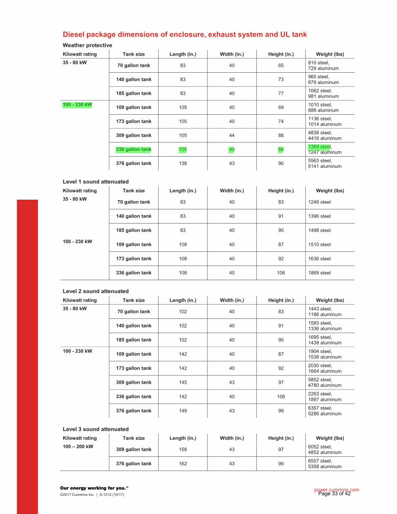
power.cummins.com ©2017 Cummins Inc. | S-1012 (10/17)
Diesel package dimensions of enclosure, exhaust system and UL tank
Weather protective
Kilowatt rating Tank size Length (in.) Width (in.) Height (in.) Weight (lbs)
35 - 80 kW 70 gallon tank 83 40 65
810 steel, 729 aluminum
140 gallon tank 83 40 73 960 steel, 879 aluminum
185 gallon tank 83 40 77 1062 steel, 981 aluminum
100 - 230 kW 109 gallon tank 105 40 69 1010 steel,
888 aluminum
173 gallon tank 105 40 74 1136 steel, 1014 aluminum
309 gallon tank 105 44 88 4838 steel, 4416 aluminum
336 gallon tank 105 40 88 1369 steel, 1247 aluminum
376 gallon tank 138 43 90 5563 steel, 5141 aluminum
Level 1 sound attenuated
Kilowatt rating Tank size Length (in.) Width (in.) Height (in.) Weight (lbs)
35 - 80 kW 70 gallon tank 83 40 83 1246 steel
140 gallon tank 83 40 91 1396 steel
185 gallon tank 83 40 95 1498 steel
100 - 230 kW 109 gallon tank 108 40 87 1510 steel
173 gallon tank 108 40 92 1636 steel
336 gallon tank 108 40 106 1869 steel
Level 2 sound attenuated
Kilowatt rating Tank size Length (in.) Width (in.) Height (in.) Weight (lbs)
35 - 80 kW 70 gallon tank 102 40 83
1443 steel, 1186 aluminum
140 gallon tank 102 40 91 1593 steel, 1336 aluminum
185 gallon tank 102 40 95 1695 steel, 1438 aluminum
100 - 230 kW 109 gallon tank 142 40 87
1904 steel, 1538 aluminum
173 gallon tank 142 40 92 2030 steel, 1664 aluminum
309 gallon tank 145 43 97 5852 steel, 4780 aluminum
336 gallon tank 142 40 106 2263 steel, 1897 aluminum
376 gallon tank 149 43 99 6357 steel, 5286 aluminum
Level 3 sound attenuated
Kilowatt rating Tank size Length (in.) Width (in.) Height (in.) Weight (lbs)
100 – 200 kW 309 gallon tank 158 43 97 6052 steel,
4852 aluminum
376 gallon tank 162 43 99 6557 steel, 5358 aluminum
Page 33 of 42
hd985
Highlight
hd985
Highlight
hd985
Callout
see below drawings for overall shipping weight and dimensions

Page 34 of 42
hd985
Line
hd985
Callout
add this weight to the open unit and fuel tank weights for overall shipping weight. Use this drawing and fuel tank drawing for overall shipping dimensions.

Page 35 of 42
hd985
Rectangle
hd985
Oval
hd985
Oval
hd985
Oval
hd985
Oval
hd985
Callout
add this weight to the open unit and enclosure weights for overall shipping weight. Use this drawing and enclosure drawing for overall shipping dimensions.
hd985
Line

Page 36 of 42
hd985
Oval
hd985
Oval

Specification sheet
Description Features Cummins Power Generation fully automatic battery chargers are constant voltage/constant current chargers incorporating a 4-stage charging algorithm. Designed for use in applications where battery life and reliability are important; these chargers, complete with built-in equalize charge capability, are ideal for stationary or portable starting battery charging service. To achieve optimum battery life, a 4-stage charging cycle is implemented. The four charging stages are constant current, high-rate taper charge, finishing charge, and maintaining charge. During the constant current cycle the charger operates at maximum possible output in the fast charge mode. During the high-rate taper charge cycle the charger stays at fast charge voltage level until battery current acceptance falls to a portion of the chargers rated output. During the finishing charge cycle the charger operates at the float voltage and completes the battery charge. During the maintaining charge cycle the charger supplies only a few milliamps required by the battery to stay at peak capability. An optional temperature sensor (A043D534) may be used to adjust charging voltage based on temperature of the battery. Use of a battery temperature sensor helps to increase battery life by preventing over or under charging. The battery temperature sensor also protects the battery from overheating. Temperature compensation sensor is required for all applications when battery charger and battery are located in different temperature or battery heater is being used. Battery chargers are field-configurable for charging either 12 or 24 VDC battery systems at 50/60 Hz operation. Simple jumper selectors enable selection of output voltage and battery type.
Protection – Surge protected to IEEE and EN standards. All models include single pole cartridge type fuses mounted on the printed circuit board to protect against input or output overcurrent. Easy installation – Clearly marked terminal blocks and panel knockouts provide convenient connections of input and output leads. User display – Output voltage and current, fault information and status are indicated on the front panel. Includes precision ammeter and voltmeter. Monitoring – Status LED indicators are provided to show the condition of the charger. LED’s on the right side of the monitor indicate operational functions for Temperature Compensation active (Green), AC on (Green ), Float (Green) or Boost (Amber) mode, as well as Battery Fault (Red). LED’s on the left side of the monitor illuminate (in Red) when Charger fail, High or Low VDC or AC fail occur. Adjustable float voltage – Float voltage can be set, using easy to understand jumpers, for optimum battery performance and life. Construction – NEMA-1 (IP20) corrosion resistant aluminum enclosure designed for wall mounting. Faults – The charger senses and annunciates the following fault conditions: AC power loss, battery overvoltage, battery under voltage, battery fault conditions and charger failure. Includes an individual 30 volt/2 amp isolated contact for each alarm. Vibration resistant design – complies with UL991 class B vibration resistance requirements. Listed – C-UL listed to UL 1236 CSA standard 22.2 No 107.2-M89. Suited for flooded and AGM lead acid and NiCd batteries in generator set installations. Warranty – 5 year CPG warranty .
©2016 Cummins Power Generation Inc. All rights reserved. Specifications are subject to change without notice. Cummins Power Generation and Cummins are registered trademarks of Cummins Inc. “Our energy working for you.” is a trademark of Cummins Power Generation. Other company, product, or service names may be trademarks or service marks of others. NAAC-5602c-EN (1/16) Page 1 of 2
Battery Charger A048G602 10A 50/60 Hz A051H785 20A 50/60 Hz
Page 37 of 42
hd985
Highlight
hd985
Highlight
hd985
Highlight

Status and Fault LED Field selectable jumper
Specifications
Performance and physical characteristics
Note: - Battery charger comes w ith default settings of 12VDC and 13.50/27.00VDC float voltage and can be changed to the battery
manufacture recommendations. Replacement printed circuit board and fuses are identif ied in the Ow ner’s Manual (10A: A050S537 and 20A: A051X126) w hich resides in Quick Serve On-Line. Service parts can be purchased through the Memphis Distribution Center. The PC board replacement instruction sheet (10A: A052N073, 20A: A053W929) and service manual (A050D829) is also available.
- Installation and application must comply w ith “section 4.5.3 batteries and battery charger” of application guide T-030 (Liquid Cooled Generator Set Application Manual A040S369).
Caution: - Higher input voltages (i.e. 480VAC or 600VAC) can be applied if a transformer w ith a 120VAC-240VAC output is installed. Higher
input voltages (i.e. 480VAC or 600VAC) can be applied if a transformer w ith a 120VAC-240VAC output is installed. For voltages higher than 240 VAC, step-dow n transformer must be used. Review the respective Ow ner/Installation manual A050S537 for 10Amp and A051X126 20A chargers for supplier recommended step-dow n transformer requirements.
- 10Amp battery charger is recommended for genset applications w ith 1 or 2 factory provided batteries. 20Amp battery charger is recommended for Cummins Genset applications w ith 3 or 4 factory provided batteries. Please consider the auxiliary DC loads connected to the genset batteries and size this charger as per the T-030 application guide to prevent misapplication issues.
- Back feed to a utility system can cause electrocution and/or property damage. Do not connect generator sets to any building electrical system except through an approved device or after building main sw itch is open.
- For professional use only. Must be installed by a qualif ied service technician. Improper installation presents hazards of electrical shock and improper operation, resulting in severe personal injury and/or property damage.
- Use this charger for charging LEAD-ACID or LIQUID ELECTROLYTE NICKEL-CA DMIUM batteries only. Do not use this battery charger for charging dry cells, alkaline, lithium, nickel-metal hydride, or sealed nickel-cadmium batteries that are commonly used w ith home appliances. These batteries may burst and cause injuries to persons and damage to property.
- Do not parallel these battery chargers w ith any other charging system.
©2016 Cummins Power Generation Inc. All rights reserved. Specifications are subject to change without notice. Cummins Power Generation and Cummins are registered trademarks of Cummins Inc. “Our energy working for you.” is a trademark of Cummins Power Generation. Other company, product, or service names may be trademarks or service marks of others. NAAC-5602c-EN (1/16) Page 2 of 2
Output: Nominal voltage 12VDC* or 24VDC
Float voltage – 12VDC batteries 12.87, 13.08, 13.31, 13.50*, 13.62, 14.30
Float voltage – 24VDC batteries 25.74, 26.16, 26.62, 27.00*, 27.24, 28.60
Equalize-volt age 6.5% above float voltage sensing
Output voltage regulation 0.5% (1/2%) line and load regulation
Maximum output current 10 or 20 amps nominal
Equalize charging Battery interactive auto-boost Input: Voltage AC 120, 208, 240 10% Frequency 60/50 Hz +5% Approximate net weight: 10A: 25 lbs. (11.36 Kg)
20A: 50 lbs. (22.68 Kg) Approximate dimension s: height x width x depth-in 10A: 12.50" x 7.66" x 6.50"(318x195x165 mm)
20A: 13.06" x 13.95" x 6.83"(332x354x173 mm)
Ambient temperatu re operation: At full rated output - 4 F to 104 F (-20 C to 45 C)
Americas 1400 73rd Avenue N.E. Minneapolis, MN 55432 USA Phone: 763 574 5000 Fax: 763 574 5298
Europe, CIS, Middle East and Africa Manston Park Columbus Ave. Manston Ramsgate Kent CT 12 5BF United Kingdom Phone 44 1843 255000 Fax 44 1843 255902
Asia Pacific 10 Toh Guan Road #07-01 TT International Tradepark Singapore 608838 Phone 65 6417 2388 Fax 65 6417 2399
Page 38 of 42
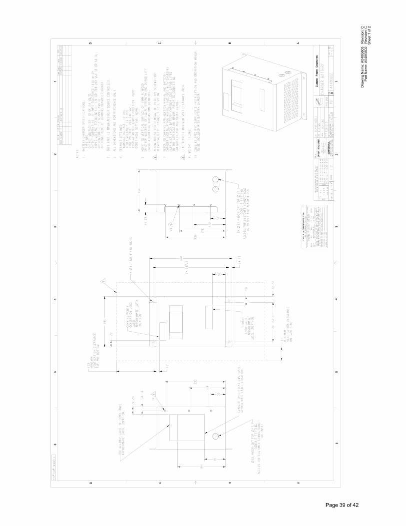
Shee
t 1 o
f 2Pa
rt N
ame:
A04
8G60
2 R
evis
ion:
CD
raw
ing
Nam
e: A
048G
603
Rev
isio
n: C
Page 39 of 42

Page 40 of 42

Effective Date: 18-July-2017 Page 1 of 2 A028U870 Issue 5
Limited Warranty
Commercial Generating Set This limited warranty applies to all Cummins Power
Generation branded commercial generating sets and associated accessories (hereinafter referred to as "Product").
This warranty covers any failures of the Product, under normal use and service, which result from a defect in material or factory workmanship.
Warranty Period: The warranty start date† is the date of initial start up, first rental, demonstration or 18 months after factory ship date, whichever is sooner. See table for details.
Continuous Power (COP) is defined as being the maximum power which the generating set is capable of delivering continuously whilst supplying a constant electrical load when operated for an unlimited number of hours per year. No overload capability is available for this rating.
Prime Power (PRP) is defined as being the maximum power which a generating set is capable of delivering continuously whilst supplying a variable electrical load when operated for an unlimited number of hours per year. The permissible average power output over 24 hours of operation shall not exceed 70% of the PRP. For applications requiring permissible average output higher than stated, a COP rating should be used.
Limited-Time Running Power (LTP) is defined as the maximum power available, under the agreed operating conditions, for which the generating set is capable of delivering for up to 500 hours of operation per year.
Emergency Standby Power (ESP) is defined as the maximum power available during a variable electrical power sequence, under the stated operating conditions, for which a generating set is capable of delivering in the event of a utility power outage or under test conditions for up to 500 hours of operationper year. The permissible average power output over 24 hours of operation shall not exceed 70% of the ESP.
Environmental Protection Agency – Stationary Emergency (EPA-SE) is defined as being the maximum power available during a variable electrical power sequence, under the stated operating conditions, for which a generator set is capable of delivering in the event of a utility power outage or under test conditions and used in strict accordance with the EPA NSPS for stationary engines, 40 CFR part 60, subparts IIII and JJJJ, where a reliable utility must be present. The permissible average power output over 24 hours of operation shall not exceed 70% of the EPA-SE.
Data Center Continuous (DCC) is defined as the maximum power which the generator is capable of delivering continuously to a constant or varying electrical load for unlimited hours in a data center application.
Base Warranty Coverage Duration (Whichever occurs first)
Rating Months Max. Hours COP 12 Unlimited PRP 12 Unlimited LTP 12 500 hrs ESP 24 1000 hrs
EPA-SE 24 Unlimited DCC 24 Unlimited
† Warranty start date for designated rental and oil and gas model
Products is determined to be date of receipt of Product by the end customer.
Cummins Power Generation Responsibilities: In the event of a failure of the Product during the warranty period due to defects in material or
workmanship, Cummins Power Generation will only be responsible for the following costs:
� All parts and labor required to repair theProduct.
� Reasonable travel expenses to and from theProduct site location.
� Maintenance items that are contaminated ordamaged by a warrantable failure.
Owner Responsibilities: The owner will be responsible for the following:
Page 41 of 42
hd985
Highlight
hd985
Highlight
hd985
Highlight
hd985
Highlight

Effective Date: 18-July-2017 Page 2 of 2 A028U870 Issue 5
� Notifying Cummins Power Generationdistributor or dealer within 30 days of thediscovery of failure.
� Installing, operating, commissioning andmaintaining the Product in accordance with
Cummins Power Generation’s publishedpolicies and guidelines.
� Providing evidence for date of commissioning.
� Providing sufficient access to and reasonableability to remove the Product from theinstallation in the event of a warrantablefailure.
� Incremental costs and expenses associatedwith Product removal and reinstallationresulting from non-standard installations.
� Costs associated with rental of generatingsets used to replace the Product beingrepaired.
� Costs associated with labor overtime andpremium shipping requested by the owner.
� All downtime expenses, fines, all applicabletaxes, and other losses resulting from awarrantable failure.
Limitations: This limited warranty does not cover Product failures resulting from:
� Inappropriate use relative to designatedpower rating.
� Inappropriate use relative to applicationguidelines.
� Inappropriate use of an EPA-SE applicationgenerator set relative to EPA’s standards.
� Normal wear and tear.� Improper and/or unauthorized installation.� Negligence, accidents or misuse.� Lack of maintenance or unauthorized repair.� Noncompliance with any Cummins Power
Generation published guideline or policy.� Use of improper or contaminated fuels,
coolants or lubricants.� Improper storage before and after
commissioning.� Owner’s delay in making Product available
after notification of potential Product problem.� Replacement parts and accessories not
authorized by Cummins Power Generation.� Use of Battle Short Mode.� Owner or operator abuse or neglect such as:
operation without adequate coolant orlubricants; overfueling; overspeeding; lack ofmaintenance to lubricating, cooling or airintake systems; late servicing andmaintenance; improper storage, starting,warm-up, run-in or shutdown practices, or forprogressive damage resulting from adefective shutdown or warning device.
� Damage to parts, fixtures, housings,attachments and accessory items that arenot part of the generating set.
This limited warranty does not cover costs resulting from:
� Difficulty in gaining access to the Product.� Damage to customer property.
A “Data center” is defined as a dedicated facility that house computers and associated equipment for data storage and data handling.
Reliable utility is defined as utility power without routine or regularly scheduled black-outs.
Please contact your local Cummins Power
Generation Distributor for clarification concerning these limitations.
CUMMINS POWER GENERATION RIGHT TO FAILED COMPONENTS:
Failed components claimed under warranty remain
the property of Cummins Power Generation.
Cummins Power Generation has the right to reclaim any failed component that has been replaced under warranty.
Extended Warranty:
Cummins Power Generation offers several levels of Extended Warranty Coverage. Please contact your
local Cummins Power Generation Distributor for details. www.power.cummins.com
THE WARRANTIES SET FORTH HEREIN ARE THE SOLE WARRANTIES MADE BY CUMMINS
POWER GENERATION IN REGARD TO THE
PRODUCT. CUMMINS POWER GENERATION MAKES NO OTHER WARRANTIES, EXPRESS OR IMPLIED, OR OF MERCHANTABILITY OR FITNESS FOR A PARTICULAR PURPOSE.
IN NO EVENT IS CUMMINS POWER
GENERATION LIABLE FOR INCIDENTAL OR CONSEQUENTIAL DAMAGES.
This limited warranty shall be enforced to the maximum extent permitted by applicable law. This limited warranty gives the owner specific rights that may vary from state to state or from jurisdiction to jurisdiction.
Product Model Number:_______________________ Product Serial Number:________________________ Date in Service:______________________________
Page 42 of 42