CSCI 3335: C OMPUTER N ETWORKS C HAPTER 3 T RANSPORT L AYER Vamsi Paruchuri University of Central...
69
CSCI 3335: COMPUTER NETWORKS CHAPTER 3 TRANSPORT LAYER Vamsi Paruchuri University of Central Arkansas http://faculty.uca.edu/vparuchuri/3335.htm Some of the material is adapted from J.F Kurose and K.W. Ro
-
Upload
morgan-dubberly -
Category
Documents
-
view
217 -
download
0
Transcript of CSCI 3335: C OMPUTER N ETWORKS C HAPTER 3 T RANSPORT L AYER Vamsi Paruchuri University of Central...
CSCI 3335 COMPUTER NETWORKS
CHAPTER 3 TRANSPORT LAYER
Vamsi ParuchuriUniversity of Central Arkansas
httpfacultyucaeduvparuchuri3335htm
Some of the material is adapted from JF Kurose and KW Ross
Transport Layer 3-2
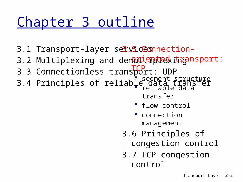
Chapter 3 outline
31 Transport-layer services32 Multiplexing and demultiplexing33 Connectionless transport UDP34 Principles of reliable data transfer
35 Connection-oriented transport TCP segment structure reliable data transfer flow control connection
management
36 Principles of congestion control
37 TCP congestion control
Transport Layer 3-3
TCP Overview RFCs 793 1122 1323 2018 2581
full duplex data bi-directional data flow
in same connection MSS maximum
segment size connection-oriented
handshaking (exchange of control msgs) inits sender receiver state before data exchange
flow controlled sender will not
overwhelm receiver
point-to-point one sender one
receiver reliable in-order byte
steam no ldquomessage
boundariesrdquo pipelined
TCP congestion and flow control set window size
send amp receive buffers
socketdoor
T C Psend buffer
T C Preceive buffer
socketdoor
segm ent
applicationwrites data
applicationreads data
Transport Layer 3-4
TCP segment structure
source port dest port
32 bits
applicationdata
(variable length)
sequence number
acknowledgement numberReceive window
Urg data pnterchecksum
FSRPAUheadlen
notused
Options (variable length)
URG urgent data (generally not used)
ACK ACK valid
PSH push data now(generally not used)
RST SYN FINconnection estab(setup teardown
commands)
bytes rcvr willingto accept
countingby bytes of data(not segments)
Internetchecksum
(as in UDP)
Transport Layer 3-5
TCP segment structure - Quiz
source port dest port
32 bits
applicationdata
(variable length)
sequence number
acknowledgement numberReceive window
Urg data pnterchecksum
FSRPAUheadlen
notused
Options (variable length)
What is the significance of each fieldWhat is TCP Header sizeWhat is max Receiver Window Size
Is it large enoughWhich field should be larger ldquoSeqrdquo
or ldquoReceive windowrdquo WhyWhat is the maximum optionsWhich flags are set in first message
in connection set up Second message Third message
Why are initial Seq set randomly
Flags SYN FIN RESET PUSH URG ACK
TCP Header Flags (6 bits)
Connection establishmenttermination SYN ndash establish sequence number field
contains valid initial sequence number FIN - terminate
RESET - abort connection because one side received something unexpected
PUSH - sender invoked push to send URG ndash indicated urgent pointer field is
valid special data - record boundary ACK - indicates Acknowledgement field
is valid
3 Transport Layer 3b-6
TCP Header ACK flag
ACK flag ndash if on then acknowledgement field valid
Once connection established no reason to turn off Acknowledgment field is always in header
so acknowledgements are free to send along with data
3 Transport Layer 3b-7
TCP Header PUSH
Intention use to indicate not to leave the data in a TCP buffer waiting for more data before it is sent
Receiver is supposed to interpret as deliver to application immediately most TCPIP implementations donrsquot delay delivery in the first place though
3 Transport Layer 3b-8
TCP Header Header Length Header Length (4 bits)
needed because options field make header variable length
Expressed in number of 32 bit words = 4 bytes
4 bits field =gt 4 bytes24 = 60 bytes 20 bytes of required header gives 40 bytes possible of options
Recall UDP header was 8 bytes
3 Transport Layer 3b-9
source port dest port
32 bits
applicationdata
(variable length)
sequence number
acknowledgement numberReceive window
Urg data pnterchecksum
FSRPAUheadlen
notused
Options (variable length)
Implications of Field Length
32 bits for sequence number (and acknowledgement) 16 bits for advertised window size
Implication for maximum window size Window size lt= frac12 SequenceNumberSpace Requirement easily satisfied because
receiver advertised window field is 16 bitsbull 232 gtgt 2 216
bull Even if increase possible advertised window to 231
that would still be ok
3 Transport Layer 3b-10
Implications of Field Length (cont)Advertised Window is 16 bit field
=gt maximum window is 64 KB Is this enough to fill the pipeline Not
always Pipeline = delayBW product 100 ms roundtrip and 100 Mbps =gt
119 MB
3 Transport Layer 3b-11
TCP Header Common Options Options used to extend and test TCP Each option is
1 byte of option kind 1 byte of option length
Examples window scale factor if donrsquot want to be limited to 216
bytes in receiver advertised window timestamp option if 32 bit sequence number space
will wrap in MSL add 32 bit timestamp to distinguish between two segments with the same sequence number
Maximum Segment Size can be set in SYN packets
3 Transport Layer 3b-12
TCP Connection Management
Recall TCP sender receiver establish ldquoconnectionrdquo before exchanging data segments
initialize TCP variables seq s buffers flow control
info (eg RcvWindow) client connection
initiator Socket clientSocket = new
Socket(hostnameport
number) server contacted by
client Socket connectionSocket =
welcomeSocketaccept()
Three way handshake
Step 1 client end system sends TCP SYN control segment to server specifies initial seq
Step 2 server end system receives SYN replies with SYNACK control segment ACKs received SYN allocates buffers specifies server-gt
receiver initial seq
Step 3 client acknowledges servers initial seq
3 Transport Layer 3b-13
Three-Way Handshake
3 Transport Layer 3b-14
Active participant(client)
Passive participant(server)
SYN SequenceNum = x
SYN + ACK SequenceNum = y
ACK Acknowledgment = y + 1
Acknowledgment = x + 1
SequenceNum = x+1
Connection Establishment
Both data channels opened at once Three-way handshake used to agree on a
set of parameters for this communication channel Initial sequence number for both sides
(random) Receiver advertised window size for both
sides Optionally Maximum Segment Size (MSS) for
each side if not specified MSS of 536 bytes is assumed to fit into 576 byte datagram
3 Transport Layer 3b-15
Initial Sequence Numbers
Chosen at random in the sequence number space
Well not really randomly intention of RFC is for initial sequence numbers to change over time 32 bit counter incrementing every 4
microseconds Vary initial sequence number to avoid
packets that are delayed in network from being delivered later and interpreted as a part of a newly established connection (to avoid reincarnations) 3 Transport Layer 3b-16
Transport Layer 3-17
TCP seq rsquos and ACKsSeq rsquos
byte stream ldquonumberrdquo of first byte in segmentrsquos data
ACKs seq of next
byte expected from other side
cumulative ACKQ how receiver
handles out-of-order segments A TCP spec
doesnrsquot say - up to implementor
Host A Host B
Seq=42 ACK=79 data = lsquoCrsquo
Seq=79 ACK=43 data = lsquoCrsquo
Seq=43 ACK=80
Usertypes
lsquoCrsquo
host ACKsreceipt
of echoedlsquoCrsquo
host ACKsreceipt of
lsquoCrsquo echoesback lsquoCrsquo
timesimple telnet scenario
Connection Termination
Each side of the bi-directional connection may be closed independently 4 messages FIN message and ACK of that
FIN in each direction Each side closes the data channel it can
send on One side can be closed and data can
continue to flow in the other direction but not usually
FINs consume sequence numbers like SYNs 3 Transport Layer 3b-18
TCP Connection Management (cont)
Closing a connection
client closes socket clientSocketclose()
Step 1 client end system sends TCP FIN control segment to server
Step 2 server receives FIN replies with ACK Closes connection sends FIN
3 Transport Layer 3b-19
client
FIN
server
ACK
ACK
FIN
close
close
closed
tim
ed w
ait
Transport Layer 3-20
Chapter 3 outline
31 Transport-layer services32 Multiplexing and demultiplexing33 Connectionless transport UDP34 Principles of reliable data transfer
35 Connection-oriented transport TCP segment structure reliable data transfer flow control connection
management
36 Principles of congestion control
37 TCP congestion control
Transport Layer 3-21
TCP reliable data transfer
TCP creates rdt service on top of IPrsquos unreliable service
pipelined segments cumulative acks TCP uses single retransmission timer
retransmissions are triggered by timeout events duplicate acks
initially consider simplified TCP sender ignore duplicate acks ignore flow control congestion control
Transport Layer 3-22
TCP Quiz -2
What are ldquoCumulative Acksrdquo What is advantage of having short time outs What is advantage of having long time outs Describe the method(s) TCP uses to detect
packet losses What is Fast Retransmit
Transport Layer 3-23
TCP sender eventsdata rcvd from app Create segment with
seq seq is byte-stream
number of first data byte in segment
start timer if not already running (think of timer as for oldest unacked segment)
expiration interval TimeOutInterval
timeout retransmit segment
that caused timeout restart timer Ack rcvd If acknowledges
previously unacked segments update what is known
to be acked start timer if there are
outstanding segments
Transport Layer 3-24
TCP sender(simplified)
NextSeqNum = InitialSeqNum SendBase = InitialSeqNum
loop (forever) switch(event)
event data received from application above create TCP segment with sequence number NextSeqNum if (timer currently not running) start timer pass segment to IP NextSeqNum = NextSeqNum + length(data)
event timer timeout retransmit not-yet-acknowledged segment with smallest sequence number start timer
event ACK received with ACK field value of y if (y gt SendBase) SendBase = y if (there are currently not-yet-acknowledged segments) start timer
end of loop forever
Commentbull SendBase-1 last cumulatively acked byteExamplebull SendBase-1 = 71
y= 73 so the rcvrwants 73+ y gt SendBase sothat new data is acked
TCP retransmission scenarios
Host A
Seq=100 20 bytes data
ACK=100
time
premature timeout
Host B
Seq=92 8 bytes data
ACK=120
Seq=92 8 bytes data
Seq=
92
tim
eout
ACK=120
Host A
Seq=92 8 bytes data
ACK=100
loss
tim
eout
lost ACK scenario
Host B
X
Seq=92 8 bytes data
ACK=100
time
Seq=
92
tim
eout
SendBase= 100
SendBase= 120
SendBase= 120
SendBase= 100
Transport Layer 3-26
TCP retransmission scenarios (more)
Host A
Seq=92 8 bytes data
ACK=100
loss
tim
eout
Cumulative ACK scenario
Host B
X
Seq=100 20 bytes data
ACK=120
time
SendBase= 120
Transport Layer 3-27
TCP Round Trip Time and TimeoutQ how to set TCP
timeout value longer than RTT
but RTT varies too short
premature timeout unnecessary
retransmissions too long slow
reaction to segment loss
Q how to estimate RTT SampleRTT measured time
from segment transmission until ACK receipt ignore retransmissions
SampleRTT will vary want estimated RTT ldquosmootherrdquo average several recent
measurements not just current SampleRTT
Transport Layer 3-28
TCP Round Trip Time and TimeoutEstimatedRTT = (1- )EstimatedRTT + SampleRTT
Exponential weighted moving average influence of past sample decreases exponentially
fast typical value = 0125
Transport Layer 3-29
Example RTT estimationRTT gaiacsumassedu to fantasiaeurecomfr
100
150
200
250
300
350
1 8 15 22 29 36 43 50 57 64 71 78 85 92 99 106
time (seconnds)
RTT
(mill
isec
onds
)
SampleRTT Estimated RTT
Transport Layer 3-30
Fast Retransmit
time-out period often relatively long long delay before resending lost packet
detect lost segments via duplicate ACKs sender often sends many segments back-to-back if segment is lost there will likely be many duplicate
ACKs
if sender receives 3 ACKs for the same data it supposes that segment after ACKed data was lost fast retransmit resend
segment before timer expires
Transport Layer 3-31
Host A
tim
eout
Host B
time
X
resend 2nd segment Seq=100 20 bytes data
Figure 337 Resending a segment after triple duplicate ACK
Seq=92 8 bytes data
ACK=100
Seq=100 20 bytes data
ACK=100
ACK=100
ACK=100
Seq=120 20 bytes dataSeq=140 20 bytes dataSeq=160 20 bytes data
ACK=180
Transport Layer 3-32
Chapter 3 outline
31 Transport-layer services32 Multiplexing and demultiplexing33 Connectionless transport UDP34 Principles of reliable data transfer
35 Connection-oriented transport TCP segment structure reliable data transfer flow control connection
management
36 Principles of congestion control
37 TCP congestion control
Transport Layer 3-33
TCP Flow Control
receive side of TCP connection has a receive buffer
speed-matching service matching the send rate to the receiving apprsquos drain rate
app process may be slow at reading from buffer
sender wonrsquot overflow
receiverrsquos buffer bytransmitting too
much too fast
flow control
Transport Layer 3-34
TCP Flow control how it works
(suppose TCP receiver discards out-of-order segments)
spare room in buffer= RcvWindow= RcvBuffer-[LastByteRcvd -
LastByteRead]
rcvr advertises spare room by including value of RcvWindow in segments
sender limits unACKed data to RcvWindow guarantees receive
buffer doesnrsquot overflow
Transport Layer 3-35
Chapter 3 outline
31 Transport-layer services32 Multiplexing and demultiplexing33 Connectionless transport UDP34 Principles of reliable data transfer
35 Connection-oriented transport TCP segment structure reliable data transfer flow control connection
management
36 Principles of congestion control
37 TCP congestion control
Transport Layer 3-36
TCP Connection Management
Recall TCP sender receiver establish ldquoconnectionrdquo before exchanging data segments
initialize TCP variables seq s buffers flow control
info (eg RcvWindow) client connection
initiator Socket clientSocket = new
Socket(hostnameport
number) server contacted by
client Socket connectionSocket =
welcomeSocketaccept()
Three way handshake
Step 1 client host sends TCP SYN segment to server specifies initial seq no data
Step 2 server host receives SYN replies with SYNACK segment server allocates buffers specifies server initial
seq Step 3 client receives
SYNACK replies with ACK segment which may contain data
Transport Layer 3-37
TCP Connection Management (cont)
Closing a connection
client closes socket clientSocketclose()
Step 1 client end system sends TCP FIN control segment to server
Step 2 server receives FIN replies with ACK Closes connection sends FIN
client
FIN
server
ACK
ACK
FIN
close
close
closed
tim
ed w
ait
Transport Layer 3-38
TCP Connection Management (cont)
Step 3 client receives FIN replies with ACK
Enters ldquotimed waitrdquo - will respond with ACK to received FINs
Step 4 server receives ACK Connection closed
client
FIN
server
ACK
ACK
FIN
closing
closing
closed
tim
ed w
ait
closed
Transport Layer 3-39
TCP Connection Management (cont)
TCP clientlifecycle
TCP serverlifecycle
Quiz Why does TCP use time outs How does timeout impact the performance of TCP What are pros and cons for short (long) timeouts How is RTT estimated by TCP What is need for flow control in TCP Describe flow control mechanism What is the primary cause of congestion Mention 3 costs of congestion What is difference between flow and congestion
control
Transport Layer 3-40
Transport Layer 3-41
Chapter 3 outline
31 Transport-layer services32 Multiplexing and demultiplexing33 Connectionless transport UDP34 Principles of reliable data transfer
35 Connection-oriented transport TCP segment structure reliable data transfer flow control connection
management
36 Principles of congestion control
37 TCP congestion control
Transport Layer 3-42
Principles of Congestion Control
Congestion informally ldquotoo many sources sending too
much data too fast for network to handlerdquo different from flow control manifestations
lost packets (buffer overflow at routers) long delays (queueing in router buffers)
a top-10 problem
Transport Layer 3-43
Causescosts of congestion scenario 1
two senders two receivers
one router infinite buffers
no retransmission
large delays when congested
maximum achievable throughput
unlimited shared output link buffers
Host Alin original data
Host B
lout
lin original data
lout
Transport Layer 3-44
Causescosts of congestion scenario 2 one router finite buffers sender retransmission of timed-out packet
application-layer input = application-layer output lin = lout
transport-layer input includes retransmissions lin lin
finite shared output link buffers
Host A
lin original data
Host B
loutlin original data plus
retransmitted data
lsquo
Transport Layer 3-45
Congestion scenario 2a ideal case sender sends
only when router buffers available
finite shared output link buffers
Host A
lin original data
Host B
loutlin original data plus
retransmitted data
copy
R2
R2lin
l out
free buffer space
Transport Layer 3-46
Host A
lin original data
Host B
loutlin original data plus
retransmitted data
copy
no buffer space
packets may get dropped at router due to full buffers sometimes lost
sender only resends if packet known to be lost (admittedly idealized)
Congestion scenario 2b known loss
Transport Layer 3-47
Congestion scenario 2b known loss
Host A
lin original data
Host B
loutlin original data plus
retransmitted data
free buffer space
packets may get dropped at router due to full buffers sometimes not lost
sender only resends if packet known to be lost (admittedly idealized)
R2
R2lin
l out
when sending at R2 some packets are retransmissions but asymptotic goodput is still R2
Transport Layer 3-48
packets may get dropped at router due to full buffers
sender times out prematurely sending two copies both of which are delivered
Host A
lin
Host B
loutlincopy
free buffer space
Congestion scenario 2c duplicates
timeout
R4
R4lin
l out
Transport Layer 3-49
packets may get dropped at router due to full buffers
sender times out prematurely sending two copies both of which are delivered
Congestion scenario 2c duplicates
ldquocostsrdquo of congestion more work (retrans) for given ldquogoodputrdquo unneeded retransmissions link carries multiple copies of
pkt decreasing goodput
R4
R4lin
l out
Transport Layer 3-50
Causescosts of congestion scenario 3 four senders multihop paths timeoutretransmit
lin
Q what happens as and increase
lin
finite shared output link buffers
Host Alin original data
Host B
lout
lin original data plus retransmitted data
Transport Layer 3-51
Causescosts of congestion scenario 3
another ldquocostrdquo of congestion when packet dropped any ldquoupstream
transmission capacity used for that packet was wasted
Host A
Host B
lo
u
t
Transport Layer 3-52
Approaches towards congestion control
end-end congestion control
no explicit feedback from network
congestion inferred from end-system observed loss delay
approach taken by TCP
network-assisted congestion control
routers provide feedback to end systems single bit indicating
congestion (SNA DECbit TCPIP ECN ATM)
explicit rate sender should send at
Two broad approaches towards congestion control
Transport Layer 3-53
Chapter 3 outline
31 Transport-layer services32 Multiplexing and demultiplexing33 Connectionless transport UDP34 Principles of reliable data transfer
35 Connection-oriented transport TCP segment structure reliable data transfer flow control connection
management
36 Principles of congestion control
37 TCP congestion control
Transport Layer 3-54
TCP congestion control additive increase multiplicative decrease
approach increase transmission rate (window size) probing for usable bandwidth until loss occurs additive increase increase cwnd by 1 MSS
every RTT until loss detected multiplicative decrease cut cwnd in half after
loss
8 Kbytes
16 Kbytes
24 Kbytes
time
congestionwindow
time
cwnd
con
gest
ion
win
dow
siz
e
saw toothbehavior probing
for bandwidth
Transport Layer 3-55
TCP Congestion Control details
sender limits transmission
LastByteSent-LastByteAcked cwnd roughly
cwnd is dynamic function of perceived network congestion
How does sender perceive congestion
loss event = timeout or 3 duplicate acks
TCP sender reduces rate (cwnd) after loss event
three mechanisms AIMD slow start conservative after
timeout events
rate = cwnd
RTT Bytessec
Transport Layer 3-56
TCP Slow Start
when connection begins increase rate exponentially until first loss event initially cwnd = 1 MSS double cwnd every RTT done by incrementing cwnd for every ACK received
summary initial rate is slow but ramps up exponentially fast
Host A
one segment
RTT
Host B
time
two segments
four segments
Transport Layer 3-57
Refinement inferring loss
after 3 dup ACKs cwnd is cut in half window then grows
linearly but after timeout event
cwnd instead set to 1 MSS
window then grows exponentially
to a threshold then grows linearly
3 dup ACKs indicates network capable of delivering some segments
timeout indicates a ldquomore alarmingrdquo congestion scenario
Philosophy
Transport Layer 3-58
Refinement
Q when should the exponential increase switch to linear
A when cwnd gets to 12 of its value before timeout
Implementation variable ssthresh on loss event ssthresh
is set to 12 of cwnd just before loss event
Can you identify different phases
Connection Timeline
3 Transport Layer 3b-59
Transport Layer 3-60
Summary TCP Congestion Control
timeoutssthresh = cwnd2
cwnd = 1 MSSdupACKcount = 0
retransmit missing segment
Lcwnd gt ssthresh
congestionavoidance
cwnd = cwnd + MSS (MSScwnd)dupACKcount = 0
transmit new segment(s) as allowed
new ACK
dupACKcount++
duplicate ACK
fastrecovery
cwnd = cwnd + MSStransmit new segment(s) as allowed
duplicate ACK
ssthresh= cwnd2cwnd = ssthresh + 3
retransmit missing segment
dupACKcount == 3
timeoutssthresh = cwnd2cwnd = 1 dupACKcount = 0retransmit missing segment
ssthresh= cwnd2cwnd = ssthresh + 3retransmit missing segment
dupACKcount == 3cwnd = ssthreshdupACKcount = 0
New ACK
slow start
timeoutssthresh = cwnd2
cwnd = 1 MSSdupACKcount = 0
retransmit missing segment
cwnd = cwnd+MSSdupACKcount = 0transmit new segment(s) as allowed
new ACKdupACKcount++
duplicate ACK
Lcwnd = 1 MSS
ssthresh = 64 KBdupACKcount = 0
NewACK
NewACK
NewACK
Transport Layer 3-61
TCP throughput
whatrsquos the average throughout of TCP as a function of window size and RTT ignore slow start
let W be the window size when loss occurs when window is W throughput is WRTT just after loss window drops to W2
throughput to W2RTT average throughout 75 WRTT
Transport Layer 3-62
TCP Futures TCP over ldquolong fat pipesrdquo
example 1500 byte segments 100ms RTT want 10 Gbps throughput
requires window size W = 83333 in-flight segments
throughput in terms of loss rate
L = 210-10 Wow ndash a very small loss rate new versions of TCP for high-speed
LRTT
MSS221
Transport Layer 3-63
fairness goal if K TCP sessions share same bottleneck link of bandwidth R each should have average rate of RK
TCP connection 1
bottleneckrouter
capacity R
TCP connection 2
TCP Fairness
Transport Layer 3-64
TCP is fair
two competing sessions additive increase gives slope of 1 as throughout increases multiplicative decrease decreases throughput proportionally
R
R
equal bandwidth share
Connection 1 throughputConnect
ion 2
th
roughput
congestion avoidance additive increaseloss decrease window by factor of 2
congestion avoidance additive increaseloss decrease window by factor of 2
Transport Layer 3-65
Fairness (more)
Fairness and UDP multimedia apps
often do not use TCP do not want rate
throttled by congestion control
instead use UDP pump audiovideo at
constant rate tolerate packet loss
Fairness and parallel TCP connections
nothing prevents app from opening parallel connections between 2 hosts
web browsers do this example link of rate R
supporting 9 connections new app asks for 1 TCP
gets rate R10 new app asks for 11 TCPs
gets R2
Transport Layer 3-66
Chapter 3 Summary principles behind
transport layer services multiplexing
demultiplexing reliable data transfer flow control congestion control
instantiation and implementation in the Internet UDP TCP
Next leaving the
network ldquoedgerdquo (application transport layers)
into the network ldquocorerdquo
Netstat
netstat ndasha ndashn Shows open connections in various states Example
Active Connections
Proto LocalAddr ForeignAddr StateTCP 000023 00000 LISTENINGTCP 1921680100139 2072008922580 CLOSE_WAITTCP 19216801001275 12832449622 ESTABLISHEDUDP 1270011070
Quiz
What are three primary mechanisms of TCP Congestion Control
What are the two TCP loss events How many packets are transmitted in
the first 4 RTT durations after a TCP connection is established
Transport Layer 3-68
Quiz (cont)
Transport Layer 3-69
- Slide 1
- Chapter 3 outline
- TCP Overview RFCs 793 1122 1323 2018 2581
- TCP segment structure
- TCP segment structure - Quiz
- TCP Header Flags (6 bits)
- TCP Header ACK flag
- TCP Header PUSH
- TCP Header Header Length
- Implications of Field Length
- Implications of Field Length (cont)
- TCP Header Common Options
- TCP Connection Management
- Three-Way Handshake
- Connection Establishment
- Initial Sequence Numbers
- TCP seq rsquos and ACKs
- Connection Termination
- TCP Connection Management (cont)
- Chapter 3 outline (2)
- TCP reliable data transfer
- TCP Quiz -2
- TCP sender events
- TCP sender (simplified)
- TCP retransmission scenarios
- TCP retransmission scenarios (more)
- TCP Round Trip Time and Timeout
- TCP Round Trip Time and Timeout (2)
- Example RTT estimation
- Fast Retransmit
- Slide 31
- Chapter 3 outline (3)
- TCP Flow Control
- TCP Flow control how it works
- Chapter 3 outline (4)
- TCP Connection Management (2)
- TCP Connection Management (cont) (2)
- TCP Connection Management (cont) (3)
- TCP Connection Management (cont)
- Quiz
- Chapter 3 outline (5)
- Principles of Congestion Control
- Causescosts of congestion scenario 1
- Causescosts of congestion scenario 2
- Congestion scenario 2a ideal case
- Congestion scenario 2b known loss
- Congestion scenario 2b known loss (2)
- Congestion scenario 2c duplicates
- Congestion scenario 2c duplicates (2)
- Causescosts of congestion scenario 3
- Causescosts of congestion scenario 3 (2)
- Approaches towards congestion control
- Chapter 3 outline (6)
- TCP congestion control additive increase multiplicative decre
- TCP Congestion Control details
- TCP Slow Start
- Refinement inferring loss
- Refinement
- Connection Timeline
- Summary TCP Congestion Control
- TCP throughput
- TCP Futures TCP over ldquolong fat pipesrdquo
- TCP Fairness
- TCP is fair
- Fairness (more)
- Chapter 3 Summary
- Netstat
- Quiz (2)
- Quiz (cont)
-
Transport Layer 3-2
Chapter 3 outline
31 Transport-layer services32 Multiplexing and demultiplexing33 Connectionless transport UDP34 Principles of reliable data transfer
35 Connection-oriented transport TCP segment structure reliable data transfer flow control connection
management
36 Principles of congestion control
37 TCP congestion control
Transport Layer 3-3
TCP Overview RFCs 793 1122 1323 2018 2581
full duplex data bi-directional data flow
in same connection MSS maximum
segment size connection-oriented
handshaking (exchange of control msgs) inits sender receiver state before data exchange
flow controlled sender will not
overwhelm receiver
point-to-point one sender one
receiver reliable in-order byte
steam no ldquomessage
boundariesrdquo pipelined
TCP congestion and flow control set window size
send amp receive buffers
socketdoor
T C Psend buffer
T C Preceive buffer
socketdoor
segm ent
applicationwrites data
applicationreads data
Transport Layer 3-4
TCP segment structure
source port dest port
32 bits
applicationdata
(variable length)
sequence number
acknowledgement numberReceive window
Urg data pnterchecksum
FSRPAUheadlen
notused
Options (variable length)
URG urgent data (generally not used)
ACK ACK valid
PSH push data now(generally not used)
RST SYN FINconnection estab(setup teardown
commands)
bytes rcvr willingto accept
countingby bytes of data(not segments)
Internetchecksum
(as in UDP)
Transport Layer 3-5
TCP segment structure - Quiz
source port dest port
32 bits
applicationdata
(variable length)
sequence number
acknowledgement numberReceive window
Urg data pnterchecksum
FSRPAUheadlen
notused
Options (variable length)
What is the significance of each fieldWhat is TCP Header sizeWhat is max Receiver Window Size
Is it large enoughWhich field should be larger ldquoSeqrdquo
or ldquoReceive windowrdquo WhyWhat is the maximum optionsWhich flags are set in first message
in connection set up Second message Third message
Why are initial Seq set randomly
Flags SYN FIN RESET PUSH URG ACK
TCP Header Flags (6 bits)
Connection establishmenttermination SYN ndash establish sequence number field
contains valid initial sequence number FIN - terminate
RESET - abort connection because one side received something unexpected
PUSH - sender invoked push to send URG ndash indicated urgent pointer field is
valid special data - record boundary ACK - indicates Acknowledgement field
is valid
3 Transport Layer 3b-6
TCP Header ACK flag
ACK flag ndash if on then acknowledgement field valid
Once connection established no reason to turn off Acknowledgment field is always in header
so acknowledgements are free to send along with data
3 Transport Layer 3b-7
TCP Header PUSH
Intention use to indicate not to leave the data in a TCP buffer waiting for more data before it is sent
Receiver is supposed to interpret as deliver to application immediately most TCPIP implementations donrsquot delay delivery in the first place though
3 Transport Layer 3b-8
TCP Header Header Length Header Length (4 bits)
needed because options field make header variable length
Expressed in number of 32 bit words = 4 bytes
4 bits field =gt 4 bytes24 = 60 bytes 20 bytes of required header gives 40 bytes possible of options
Recall UDP header was 8 bytes
3 Transport Layer 3b-9
source port dest port
32 bits
applicationdata
(variable length)
sequence number
acknowledgement numberReceive window
Urg data pnterchecksum
FSRPAUheadlen
notused
Options (variable length)
Implications of Field Length
32 bits for sequence number (and acknowledgement) 16 bits for advertised window size
Implication for maximum window size Window size lt= frac12 SequenceNumberSpace Requirement easily satisfied because
receiver advertised window field is 16 bitsbull 232 gtgt 2 216
bull Even if increase possible advertised window to 231
that would still be ok
3 Transport Layer 3b-10
Implications of Field Length (cont)Advertised Window is 16 bit field
=gt maximum window is 64 KB Is this enough to fill the pipeline Not
always Pipeline = delayBW product 100 ms roundtrip and 100 Mbps =gt
119 MB
3 Transport Layer 3b-11
TCP Header Common Options Options used to extend and test TCP Each option is
1 byte of option kind 1 byte of option length
Examples window scale factor if donrsquot want to be limited to 216
bytes in receiver advertised window timestamp option if 32 bit sequence number space
will wrap in MSL add 32 bit timestamp to distinguish between two segments with the same sequence number
Maximum Segment Size can be set in SYN packets
3 Transport Layer 3b-12
TCP Connection Management
Recall TCP sender receiver establish ldquoconnectionrdquo before exchanging data segments
initialize TCP variables seq s buffers flow control
info (eg RcvWindow) client connection
initiator Socket clientSocket = new
Socket(hostnameport
number) server contacted by
client Socket connectionSocket =
welcomeSocketaccept()
Three way handshake
Step 1 client end system sends TCP SYN control segment to server specifies initial seq
Step 2 server end system receives SYN replies with SYNACK control segment ACKs received SYN allocates buffers specifies server-gt
receiver initial seq
Step 3 client acknowledges servers initial seq
3 Transport Layer 3b-13
Three-Way Handshake
3 Transport Layer 3b-14
Active participant(client)
Passive participant(server)
SYN SequenceNum = x
SYN + ACK SequenceNum = y
ACK Acknowledgment = y + 1
Acknowledgment = x + 1
SequenceNum = x+1
Connection Establishment
Both data channels opened at once Three-way handshake used to agree on a
set of parameters for this communication channel Initial sequence number for both sides
(random) Receiver advertised window size for both
sides Optionally Maximum Segment Size (MSS) for
each side if not specified MSS of 536 bytes is assumed to fit into 576 byte datagram
3 Transport Layer 3b-15
Initial Sequence Numbers
Chosen at random in the sequence number space
Well not really randomly intention of RFC is for initial sequence numbers to change over time 32 bit counter incrementing every 4
microseconds Vary initial sequence number to avoid
packets that are delayed in network from being delivered later and interpreted as a part of a newly established connection (to avoid reincarnations) 3 Transport Layer 3b-16
Transport Layer 3-17
TCP seq rsquos and ACKsSeq rsquos
byte stream ldquonumberrdquo of first byte in segmentrsquos data
ACKs seq of next
byte expected from other side
cumulative ACKQ how receiver
handles out-of-order segments A TCP spec
doesnrsquot say - up to implementor
Host A Host B
Seq=42 ACK=79 data = lsquoCrsquo
Seq=79 ACK=43 data = lsquoCrsquo
Seq=43 ACK=80
Usertypes
lsquoCrsquo
host ACKsreceipt
of echoedlsquoCrsquo
host ACKsreceipt of
lsquoCrsquo echoesback lsquoCrsquo
timesimple telnet scenario
Connection Termination
Each side of the bi-directional connection may be closed independently 4 messages FIN message and ACK of that
FIN in each direction Each side closes the data channel it can
send on One side can be closed and data can
continue to flow in the other direction but not usually
FINs consume sequence numbers like SYNs 3 Transport Layer 3b-18
TCP Connection Management (cont)
Closing a connection
client closes socket clientSocketclose()
Step 1 client end system sends TCP FIN control segment to server
Step 2 server receives FIN replies with ACK Closes connection sends FIN
3 Transport Layer 3b-19
client
FIN
server
ACK
ACK
FIN
close
close
closed
tim
ed w
ait
Transport Layer 3-20
Chapter 3 outline
31 Transport-layer services32 Multiplexing and demultiplexing33 Connectionless transport UDP34 Principles of reliable data transfer
35 Connection-oriented transport TCP segment structure reliable data transfer flow control connection
management
36 Principles of congestion control
37 TCP congestion control
Transport Layer 3-21
TCP reliable data transfer
TCP creates rdt service on top of IPrsquos unreliable service
pipelined segments cumulative acks TCP uses single retransmission timer
retransmissions are triggered by timeout events duplicate acks
initially consider simplified TCP sender ignore duplicate acks ignore flow control congestion control
Transport Layer 3-22
TCP Quiz -2
What are ldquoCumulative Acksrdquo What is advantage of having short time outs What is advantage of having long time outs Describe the method(s) TCP uses to detect
packet losses What is Fast Retransmit
Transport Layer 3-23
TCP sender eventsdata rcvd from app Create segment with
seq seq is byte-stream
number of first data byte in segment
start timer if not already running (think of timer as for oldest unacked segment)
expiration interval TimeOutInterval
timeout retransmit segment
that caused timeout restart timer Ack rcvd If acknowledges
previously unacked segments update what is known
to be acked start timer if there are
outstanding segments
Transport Layer 3-24
TCP sender(simplified)
NextSeqNum = InitialSeqNum SendBase = InitialSeqNum
loop (forever) switch(event)
event data received from application above create TCP segment with sequence number NextSeqNum if (timer currently not running) start timer pass segment to IP NextSeqNum = NextSeqNum + length(data)
event timer timeout retransmit not-yet-acknowledged segment with smallest sequence number start timer
event ACK received with ACK field value of y if (y gt SendBase) SendBase = y if (there are currently not-yet-acknowledged segments) start timer
end of loop forever
Commentbull SendBase-1 last cumulatively acked byteExamplebull SendBase-1 = 71
y= 73 so the rcvrwants 73+ y gt SendBase sothat new data is acked
TCP retransmission scenarios
Host A
Seq=100 20 bytes data
ACK=100
time
premature timeout
Host B
Seq=92 8 bytes data
ACK=120
Seq=92 8 bytes data
Seq=
92
tim
eout
ACK=120
Host A
Seq=92 8 bytes data
ACK=100
loss
tim
eout
lost ACK scenario
Host B
X
Seq=92 8 bytes data
ACK=100
time
Seq=
92
tim
eout
SendBase= 100
SendBase= 120
SendBase= 120
SendBase= 100
Transport Layer 3-26
TCP retransmission scenarios (more)
Host A
Seq=92 8 bytes data
ACK=100
loss
tim
eout
Cumulative ACK scenario
Host B
X
Seq=100 20 bytes data
ACK=120
time
SendBase= 120
Transport Layer 3-27
TCP Round Trip Time and TimeoutQ how to set TCP
timeout value longer than RTT
but RTT varies too short
premature timeout unnecessary
retransmissions too long slow
reaction to segment loss
Q how to estimate RTT SampleRTT measured time
from segment transmission until ACK receipt ignore retransmissions
SampleRTT will vary want estimated RTT ldquosmootherrdquo average several recent
measurements not just current SampleRTT
Transport Layer 3-28
TCP Round Trip Time and TimeoutEstimatedRTT = (1- )EstimatedRTT + SampleRTT
Exponential weighted moving average influence of past sample decreases exponentially
fast typical value = 0125
Transport Layer 3-29
Example RTT estimationRTT gaiacsumassedu to fantasiaeurecomfr
100
150
200
250
300
350
1 8 15 22 29 36 43 50 57 64 71 78 85 92 99 106
time (seconnds)
RTT
(mill
isec
onds
)
SampleRTT Estimated RTT
Transport Layer 3-30
Fast Retransmit
time-out period often relatively long long delay before resending lost packet
detect lost segments via duplicate ACKs sender often sends many segments back-to-back if segment is lost there will likely be many duplicate
ACKs
if sender receives 3 ACKs for the same data it supposes that segment after ACKed data was lost fast retransmit resend
segment before timer expires
Transport Layer 3-31
Host A
tim
eout
Host B
time
X
resend 2nd segment Seq=100 20 bytes data
Figure 337 Resending a segment after triple duplicate ACK
Seq=92 8 bytes data
ACK=100
Seq=100 20 bytes data
ACK=100
ACK=100
ACK=100
Seq=120 20 bytes dataSeq=140 20 bytes dataSeq=160 20 bytes data
ACK=180
Transport Layer 3-32
Chapter 3 outline
31 Transport-layer services32 Multiplexing and demultiplexing33 Connectionless transport UDP34 Principles of reliable data transfer
35 Connection-oriented transport TCP segment structure reliable data transfer flow control connection
management
36 Principles of congestion control
37 TCP congestion control
Transport Layer 3-33
TCP Flow Control
receive side of TCP connection has a receive buffer
speed-matching service matching the send rate to the receiving apprsquos drain rate
app process may be slow at reading from buffer
sender wonrsquot overflow
receiverrsquos buffer bytransmitting too
much too fast
flow control
Transport Layer 3-34
TCP Flow control how it works
(suppose TCP receiver discards out-of-order segments)
spare room in buffer= RcvWindow= RcvBuffer-[LastByteRcvd -
LastByteRead]
rcvr advertises spare room by including value of RcvWindow in segments
sender limits unACKed data to RcvWindow guarantees receive
buffer doesnrsquot overflow
Transport Layer 3-35
Chapter 3 outline
31 Transport-layer services32 Multiplexing and demultiplexing33 Connectionless transport UDP34 Principles of reliable data transfer
35 Connection-oriented transport TCP segment structure reliable data transfer flow control connection
management
36 Principles of congestion control
37 TCP congestion control
Transport Layer 3-36
TCP Connection Management
Recall TCP sender receiver establish ldquoconnectionrdquo before exchanging data segments
initialize TCP variables seq s buffers flow control
info (eg RcvWindow) client connection
initiator Socket clientSocket = new
Socket(hostnameport
number) server contacted by
client Socket connectionSocket =
welcomeSocketaccept()
Three way handshake
Step 1 client host sends TCP SYN segment to server specifies initial seq no data
Step 2 server host receives SYN replies with SYNACK segment server allocates buffers specifies server initial
seq Step 3 client receives
SYNACK replies with ACK segment which may contain data
Transport Layer 3-37
TCP Connection Management (cont)
Closing a connection
client closes socket clientSocketclose()
Step 1 client end system sends TCP FIN control segment to server
Step 2 server receives FIN replies with ACK Closes connection sends FIN
client
FIN
server
ACK
ACK
FIN
close
close
closed
tim
ed w
ait
Transport Layer 3-38
TCP Connection Management (cont)
Step 3 client receives FIN replies with ACK
Enters ldquotimed waitrdquo - will respond with ACK to received FINs
Step 4 server receives ACK Connection closed
client
FIN
server
ACK
ACK
FIN
closing
closing
closed
tim
ed w
ait
closed
Transport Layer 3-39
TCP Connection Management (cont)
TCP clientlifecycle
TCP serverlifecycle
Quiz Why does TCP use time outs How does timeout impact the performance of TCP What are pros and cons for short (long) timeouts How is RTT estimated by TCP What is need for flow control in TCP Describe flow control mechanism What is the primary cause of congestion Mention 3 costs of congestion What is difference between flow and congestion
control
Transport Layer 3-40
Transport Layer 3-41
Chapter 3 outline
31 Transport-layer services32 Multiplexing and demultiplexing33 Connectionless transport UDP34 Principles of reliable data transfer
35 Connection-oriented transport TCP segment structure reliable data transfer flow control connection
management
36 Principles of congestion control
37 TCP congestion control
Transport Layer 3-42
Principles of Congestion Control
Congestion informally ldquotoo many sources sending too
much data too fast for network to handlerdquo different from flow control manifestations
lost packets (buffer overflow at routers) long delays (queueing in router buffers)
a top-10 problem
Transport Layer 3-43
Causescosts of congestion scenario 1
two senders two receivers
one router infinite buffers
no retransmission
large delays when congested
maximum achievable throughput
unlimited shared output link buffers
Host Alin original data
Host B
lout
lin original data
lout
Transport Layer 3-44
Causescosts of congestion scenario 2 one router finite buffers sender retransmission of timed-out packet
application-layer input = application-layer output lin = lout
transport-layer input includes retransmissions lin lin
finite shared output link buffers
Host A
lin original data
Host B
loutlin original data plus
retransmitted data
lsquo
Transport Layer 3-45
Congestion scenario 2a ideal case sender sends
only when router buffers available
finite shared output link buffers
Host A
lin original data
Host B
loutlin original data plus
retransmitted data
copy
R2
R2lin
l out
free buffer space
Transport Layer 3-46
Host A
lin original data
Host B
loutlin original data plus
retransmitted data
copy
no buffer space
packets may get dropped at router due to full buffers sometimes lost
sender only resends if packet known to be lost (admittedly idealized)
Congestion scenario 2b known loss
Transport Layer 3-47
Congestion scenario 2b known loss
Host A
lin original data
Host B
loutlin original data plus
retransmitted data
free buffer space
packets may get dropped at router due to full buffers sometimes not lost
sender only resends if packet known to be lost (admittedly idealized)
R2
R2lin
l out
when sending at R2 some packets are retransmissions but asymptotic goodput is still R2
Transport Layer 3-48
packets may get dropped at router due to full buffers
sender times out prematurely sending two copies both of which are delivered
Host A
lin
Host B
loutlincopy
free buffer space
Congestion scenario 2c duplicates
timeout
R4
R4lin
l out
Transport Layer 3-49
packets may get dropped at router due to full buffers
sender times out prematurely sending two copies both of which are delivered
Congestion scenario 2c duplicates
ldquocostsrdquo of congestion more work (retrans) for given ldquogoodputrdquo unneeded retransmissions link carries multiple copies of
pkt decreasing goodput
R4
R4lin
l out
Transport Layer 3-50
Causescosts of congestion scenario 3 four senders multihop paths timeoutretransmit
lin
Q what happens as and increase
lin
finite shared output link buffers
Host Alin original data
Host B
lout
lin original data plus retransmitted data
Transport Layer 3-51
Causescosts of congestion scenario 3
another ldquocostrdquo of congestion when packet dropped any ldquoupstream
transmission capacity used for that packet was wasted
Host A
Host B
lo
u
t
Transport Layer 3-52
Approaches towards congestion control
end-end congestion control
no explicit feedback from network
congestion inferred from end-system observed loss delay
approach taken by TCP
network-assisted congestion control
routers provide feedback to end systems single bit indicating
congestion (SNA DECbit TCPIP ECN ATM)
explicit rate sender should send at
Two broad approaches towards congestion control
Transport Layer 3-53
Chapter 3 outline
31 Transport-layer services32 Multiplexing and demultiplexing33 Connectionless transport UDP34 Principles of reliable data transfer
35 Connection-oriented transport TCP segment structure reliable data transfer flow control connection
management
36 Principles of congestion control
37 TCP congestion control
Transport Layer 3-54
TCP congestion control additive increase multiplicative decrease
approach increase transmission rate (window size) probing for usable bandwidth until loss occurs additive increase increase cwnd by 1 MSS
every RTT until loss detected multiplicative decrease cut cwnd in half after
loss
8 Kbytes
16 Kbytes
24 Kbytes
time
congestionwindow
time
cwnd
con
gest
ion
win
dow
siz
e
saw toothbehavior probing
for bandwidth
Transport Layer 3-55
TCP Congestion Control details
sender limits transmission
LastByteSent-LastByteAcked cwnd roughly
cwnd is dynamic function of perceived network congestion
How does sender perceive congestion
loss event = timeout or 3 duplicate acks
TCP sender reduces rate (cwnd) after loss event
three mechanisms AIMD slow start conservative after
timeout events
rate = cwnd
RTT Bytessec
Transport Layer 3-56
TCP Slow Start
when connection begins increase rate exponentially until first loss event initially cwnd = 1 MSS double cwnd every RTT done by incrementing cwnd for every ACK received
summary initial rate is slow but ramps up exponentially fast
Host A
one segment
RTT
Host B
time
two segments
four segments
Transport Layer 3-57
Refinement inferring loss
after 3 dup ACKs cwnd is cut in half window then grows
linearly but after timeout event
cwnd instead set to 1 MSS
window then grows exponentially
to a threshold then grows linearly
3 dup ACKs indicates network capable of delivering some segments
timeout indicates a ldquomore alarmingrdquo congestion scenario
Philosophy
Transport Layer 3-58
Refinement
Q when should the exponential increase switch to linear
A when cwnd gets to 12 of its value before timeout
Implementation variable ssthresh on loss event ssthresh
is set to 12 of cwnd just before loss event
Can you identify different phases
Connection Timeline
3 Transport Layer 3b-59
Transport Layer 3-60
Summary TCP Congestion Control
timeoutssthresh = cwnd2
cwnd = 1 MSSdupACKcount = 0
retransmit missing segment
Lcwnd gt ssthresh
congestionavoidance
cwnd = cwnd + MSS (MSScwnd)dupACKcount = 0
transmit new segment(s) as allowed
new ACK
dupACKcount++
duplicate ACK
fastrecovery
cwnd = cwnd + MSStransmit new segment(s) as allowed
duplicate ACK
ssthresh= cwnd2cwnd = ssthresh + 3
retransmit missing segment
dupACKcount == 3
timeoutssthresh = cwnd2cwnd = 1 dupACKcount = 0retransmit missing segment
ssthresh= cwnd2cwnd = ssthresh + 3retransmit missing segment
dupACKcount == 3cwnd = ssthreshdupACKcount = 0
New ACK
slow start
timeoutssthresh = cwnd2
cwnd = 1 MSSdupACKcount = 0
retransmit missing segment
cwnd = cwnd+MSSdupACKcount = 0transmit new segment(s) as allowed
new ACKdupACKcount++
duplicate ACK
Lcwnd = 1 MSS
ssthresh = 64 KBdupACKcount = 0
NewACK
NewACK
NewACK
Transport Layer 3-61
TCP throughput
whatrsquos the average throughout of TCP as a function of window size and RTT ignore slow start
let W be the window size when loss occurs when window is W throughput is WRTT just after loss window drops to W2
throughput to W2RTT average throughout 75 WRTT
Transport Layer 3-62
TCP Futures TCP over ldquolong fat pipesrdquo
example 1500 byte segments 100ms RTT want 10 Gbps throughput
requires window size W = 83333 in-flight segments
throughput in terms of loss rate
L = 210-10 Wow ndash a very small loss rate new versions of TCP for high-speed
LRTT
MSS221
Transport Layer 3-63
fairness goal if K TCP sessions share same bottleneck link of bandwidth R each should have average rate of RK
TCP connection 1
bottleneckrouter
capacity R
TCP connection 2
TCP Fairness
Transport Layer 3-64
TCP is fair
two competing sessions additive increase gives slope of 1 as throughout increases multiplicative decrease decreases throughput proportionally
R
R
equal bandwidth share
Connection 1 throughputConnect
ion 2
th
roughput
congestion avoidance additive increaseloss decrease window by factor of 2
congestion avoidance additive increaseloss decrease window by factor of 2
Transport Layer 3-65
Fairness (more)
Fairness and UDP multimedia apps
often do not use TCP do not want rate
throttled by congestion control
instead use UDP pump audiovideo at
constant rate tolerate packet loss
Fairness and parallel TCP connections
nothing prevents app from opening parallel connections between 2 hosts
web browsers do this example link of rate R
supporting 9 connections new app asks for 1 TCP
gets rate R10 new app asks for 11 TCPs
gets R2
Transport Layer 3-66
Chapter 3 Summary principles behind
transport layer services multiplexing
demultiplexing reliable data transfer flow control congestion control
instantiation and implementation in the Internet UDP TCP
Next leaving the
network ldquoedgerdquo (application transport layers)
into the network ldquocorerdquo
Netstat
netstat ndasha ndashn Shows open connections in various states Example
Active Connections
Proto LocalAddr ForeignAddr StateTCP 000023 00000 LISTENINGTCP 1921680100139 2072008922580 CLOSE_WAITTCP 19216801001275 12832449622 ESTABLISHEDUDP 1270011070
Quiz
What are three primary mechanisms of TCP Congestion Control
What are the two TCP loss events How many packets are transmitted in
the first 4 RTT durations after a TCP connection is established
Transport Layer 3-68
Quiz (cont)
Transport Layer 3-69
- Slide 1
- Chapter 3 outline
- TCP Overview RFCs 793 1122 1323 2018 2581
- TCP segment structure
- TCP segment structure - Quiz
- TCP Header Flags (6 bits)
- TCP Header ACK flag
- TCP Header PUSH
- TCP Header Header Length
- Implications of Field Length
- Implications of Field Length (cont)
- TCP Header Common Options
- TCP Connection Management
- Three-Way Handshake
- Connection Establishment
- Initial Sequence Numbers
- TCP seq rsquos and ACKs
- Connection Termination
- TCP Connection Management (cont)
- Chapter 3 outline (2)
- TCP reliable data transfer
- TCP Quiz -2
- TCP sender events
- TCP sender (simplified)
- TCP retransmission scenarios
- TCP retransmission scenarios (more)
- TCP Round Trip Time and Timeout
- TCP Round Trip Time and Timeout (2)
- Example RTT estimation
- Fast Retransmit
- Slide 31
- Chapter 3 outline (3)
- TCP Flow Control
- TCP Flow control how it works
- Chapter 3 outline (4)
- TCP Connection Management (2)
- TCP Connection Management (cont) (2)
- TCP Connection Management (cont) (3)
- TCP Connection Management (cont)
- Quiz
- Chapter 3 outline (5)
- Principles of Congestion Control
- Causescosts of congestion scenario 1
- Causescosts of congestion scenario 2
- Congestion scenario 2a ideal case
- Congestion scenario 2b known loss
- Congestion scenario 2b known loss (2)
- Congestion scenario 2c duplicates
- Congestion scenario 2c duplicates (2)
- Causescosts of congestion scenario 3
- Causescosts of congestion scenario 3 (2)
- Approaches towards congestion control
- Chapter 3 outline (6)
- TCP congestion control additive increase multiplicative decre
- TCP Congestion Control details
- TCP Slow Start
- Refinement inferring loss
- Refinement
- Connection Timeline
- Summary TCP Congestion Control
- TCP throughput
- TCP Futures TCP over ldquolong fat pipesrdquo
- TCP Fairness
- TCP is fair
- Fairness (more)
- Chapter 3 Summary
- Netstat
- Quiz (2)
- Quiz (cont)
-
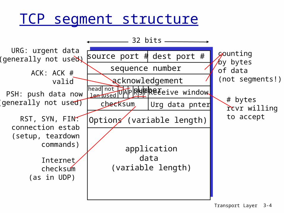
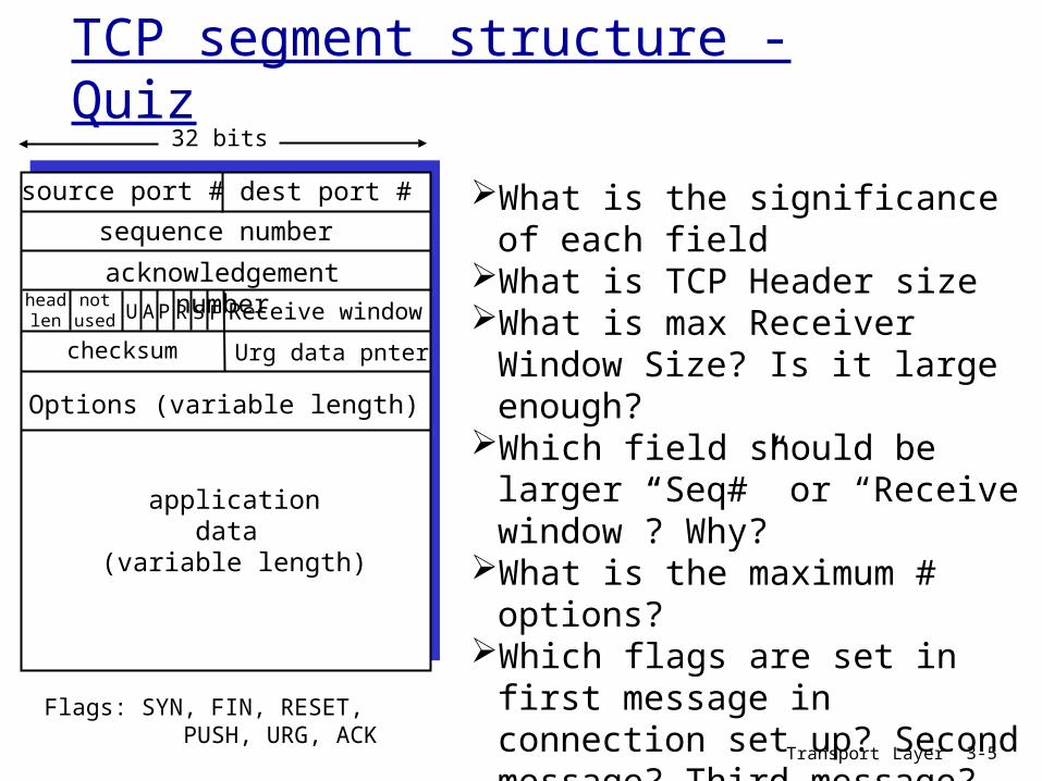
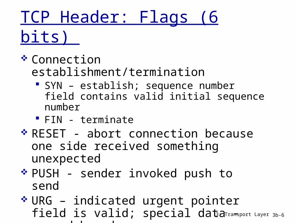
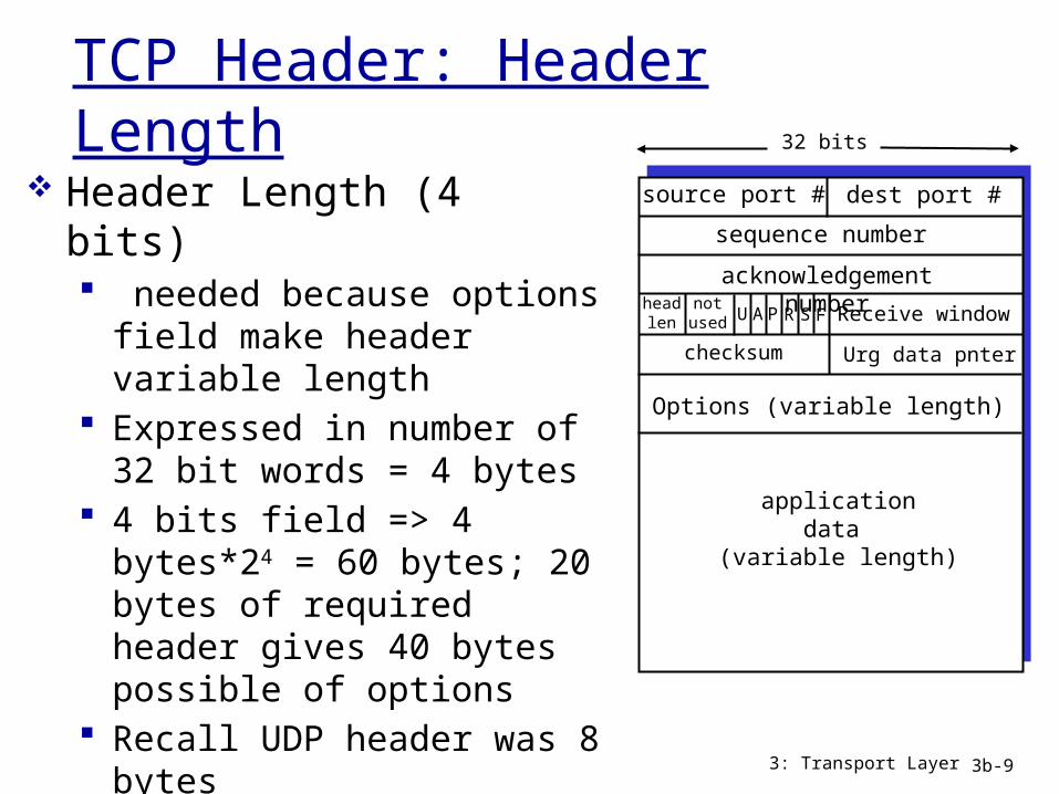
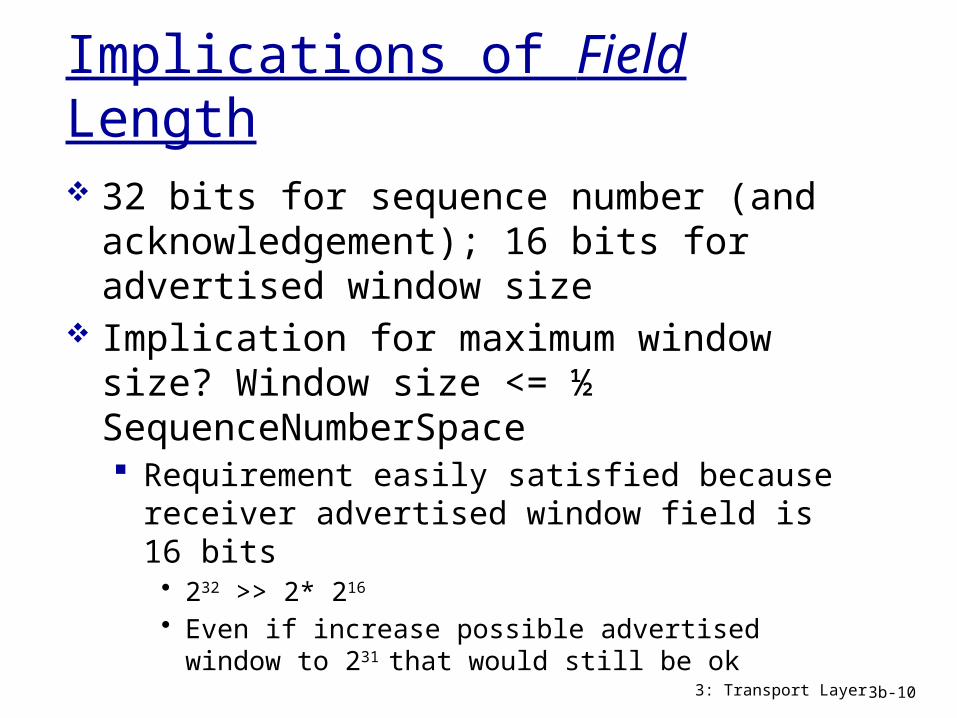
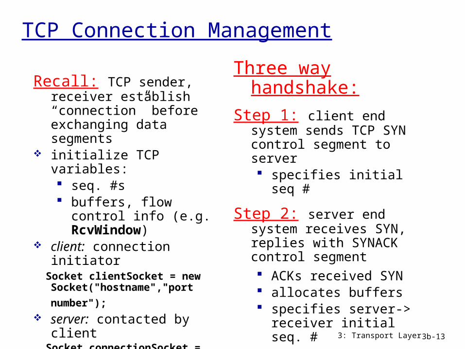
TCP Connection Management
Recall TCP sender receiver establish ldquoconnectionrdquo before exchanging data segments
initialize TCP variables seq s buffers flow control
info (eg RcvWindow) client connection
initiator Socket clientSocket = new
Socket(hostnameport
number) server contacted by
client Socket connectionSocket =
welcomeSocketaccept()
Three way handshake
Step 1 client end system sends TCP SYN control segment to server specifies initial seq
Step 2 server end system receives SYN replies with SYNACK control segment ACKs received SYN allocates buffers specifies server-gt
receiver initial seq
Step 3 client acknowledges servers initial seq
3 Transport Layer 3b-13
Three-Way Handshake
3 Transport Layer 3b-14
Active participant(client)
Passive participant(server)
SYN SequenceNum = x
SYN + ACK SequenceNum = y
ACK Acknowledgment = y + 1
Acknowledgment = x + 1
SequenceNum = x+1
Connection Establishment
Both data channels opened at once Three-way handshake used to agree on a
set of parameters for this communication channel Initial sequence number for both sides
(random) Receiver advertised window size for both
sides Optionally Maximum Segment Size (MSS) for
each side if not specified MSS of 536 bytes is assumed to fit into 576 byte datagram
3 Transport Layer 3b-15
Initial Sequence Numbers
Chosen at random in the sequence number space
Well not really randomly intention of RFC is for initial sequence numbers to change over time 32 bit counter incrementing every 4
microseconds Vary initial sequence number to avoid
packets that are delayed in network from being delivered later and interpreted as a part of a newly established connection (to avoid reincarnations) 3 Transport Layer 3b-16
Transport Layer 3-17
TCP seq rsquos and ACKsSeq rsquos
byte stream ldquonumberrdquo of first byte in segmentrsquos data
ACKs seq of next
byte expected from other side
cumulative ACKQ how receiver
handles out-of-order segments A TCP spec
doesnrsquot say - up to implementor
Host A Host B
Seq=42 ACK=79 data = lsquoCrsquo
Seq=79 ACK=43 data = lsquoCrsquo
Seq=43 ACK=80
Usertypes
lsquoCrsquo
host ACKsreceipt
of echoedlsquoCrsquo
host ACKsreceipt of
lsquoCrsquo echoesback lsquoCrsquo
timesimple telnet scenario
Connection Termination
Each side of the bi-directional connection may be closed independently 4 messages FIN message and ACK of that
FIN in each direction Each side closes the data channel it can
send on One side can be closed and data can
continue to flow in the other direction but not usually
FINs consume sequence numbers like SYNs 3 Transport Layer 3b-18
TCP Connection Management (cont)
Closing a connection
client closes socket clientSocketclose()
Step 1 client end system sends TCP FIN control segment to server
Step 2 server receives FIN replies with ACK Closes connection sends FIN
3 Transport Layer 3b-19
client
FIN
server
ACK
ACK
FIN
close
close
closed
tim
ed w
ait
Transport Layer 3-20
Chapter 3 outline
31 Transport-layer services32 Multiplexing and demultiplexing33 Connectionless transport UDP34 Principles of reliable data transfer
35 Connection-oriented transport TCP segment structure reliable data transfer flow control connection
management
36 Principles of congestion control
37 TCP congestion control
Transport Layer 3-21
TCP reliable data transfer
TCP creates rdt service on top of IPrsquos unreliable service
pipelined segments cumulative acks TCP uses single retransmission timer
retransmissions are triggered by timeout events duplicate acks
initially consider simplified TCP sender ignore duplicate acks ignore flow control congestion control
Transport Layer 3-22
TCP Quiz -2
What are ldquoCumulative Acksrdquo What is advantage of having short time outs What is advantage of having long time outs Describe the method(s) TCP uses to detect
packet losses What is Fast Retransmit
Transport Layer 3-23
TCP sender eventsdata rcvd from app Create segment with
seq seq is byte-stream
number of first data byte in segment
start timer if not already running (think of timer as for oldest unacked segment)
expiration interval TimeOutInterval
timeout retransmit segment
that caused timeout restart timer Ack rcvd If acknowledges
previously unacked segments update what is known
to be acked start timer if there are
outstanding segments
Transport Layer 3-24
TCP sender(simplified)
NextSeqNum = InitialSeqNum SendBase = InitialSeqNum
loop (forever) switch(event)
event data received from application above create TCP segment with sequence number NextSeqNum if (timer currently not running) start timer pass segment to IP NextSeqNum = NextSeqNum + length(data)
event timer timeout retransmit not-yet-acknowledged segment with smallest sequence number start timer
event ACK received with ACK field value of y if (y gt SendBase) SendBase = y if (there are currently not-yet-acknowledged segments) start timer
end of loop forever
Commentbull SendBase-1 last cumulatively acked byteExamplebull SendBase-1 = 71
y= 73 so the rcvrwants 73+ y gt SendBase sothat new data is acked
TCP retransmission scenarios
Host A
Seq=100 20 bytes data
ACK=100
time
premature timeout
Host B
Seq=92 8 bytes data
ACK=120
Seq=92 8 bytes data
Seq=
92
tim
eout
ACK=120
Host A
Seq=92 8 bytes data
ACK=100
loss
tim
eout
lost ACK scenario
Host B
X
Seq=92 8 bytes data
ACK=100
time
Seq=
92
tim
eout
SendBase= 100
SendBase= 120
SendBase= 120
SendBase= 100
Transport Layer 3-26
TCP retransmission scenarios (more)
Host A
Seq=92 8 bytes data
ACK=100
loss
tim
eout
Cumulative ACK scenario
Host B
X
Seq=100 20 bytes data
ACK=120
time
SendBase= 120
Transport Layer 3-27
TCP Round Trip Time and TimeoutQ how to set TCP
timeout value longer than RTT
but RTT varies too short
premature timeout unnecessary
retransmissions too long slow
reaction to segment loss
Q how to estimate RTT SampleRTT measured time
from segment transmission until ACK receipt ignore retransmissions
SampleRTT will vary want estimated RTT ldquosmootherrdquo average several recent
measurements not just current SampleRTT
Transport Layer 3-28
TCP Round Trip Time and TimeoutEstimatedRTT = (1- )EstimatedRTT + SampleRTT
Exponential weighted moving average influence of past sample decreases exponentially
fast typical value = 0125
Transport Layer 3-29
Example RTT estimationRTT gaiacsumassedu to fantasiaeurecomfr
100
150
200
250
300
350
1 8 15 22 29 36 43 50 57 64 71 78 85 92 99 106
time (seconnds)
RTT
(mill
isec
onds
)
SampleRTT Estimated RTT
Transport Layer 3-30
Fast Retransmit
time-out period often relatively long long delay before resending lost packet
detect lost segments via duplicate ACKs sender often sends many segments back-to-back if segment is lost there will likely be many duplicate
ACKs
if sender receives 3 ACKs for the same data it supposes that segment after ACKed data was lost fast retransmit resend
segment before timer expires
Transport Layer 3-31
Host A
tim
eout
Host B
time
X
resend 2nd segment Seq=100 20 bytes data
Figure 337 Resending a segment after triple duplicate ACK
Seq=92 8 bytes data
ACK=100
Seq=100 20 bytes data
ACK=100
ACK=100
ACK=100
Seq=120 20 bytes dataSeq=140 20 bytes dataSeq=160 20 bytes data
ACK=180
Transport Layer 3-32
Chapter 3 outline
31 Transport-layer services32 Multiplexing and demultiplexing33 Connectionless transport UDP34 Principles of reliable data transfer
35 Connection-oriented transport TCP segment structure reliable data transfer flow control connection
management
36 Principles of congestion control
37 TCP congestion control
Transport Layer 3-33
TCP Flow Control
receive side of TCP connection has a receive buffer
speed-matching service matching the send rate to the receiving apprsquos drain rate
app process may be slow at reading from buffer
sender wonrsquot overflow
receiverrsquos buffer bytransmitting too
much too fast
flow control
Transport Layer 3-34
TCP Flow control how it works
(suppose TCP receiver discards out-of-order segments)
spare room in buffer= RcvWindow= RcvBuffer-[LastByteRcvd -
LastByteRead]
rcvr advertises spare room by including value of RcvWindow in segments
sender limits unACKed data to RcvWindow guarantees receive
buffer doesnrsquot overflow
Transport Layer 3-35
Chapter 3 outline
31 Transport-layer services32 Multiplexing and demultiplexing33 Connectionless transport UDP34 Principles of reliable data transfer
35 Connection-oriented transport TCP segment structure reliable data transfer flow control connection
management
36 Principles of congestion control
37 TCP congestion control
Transport Layer 3-36
TCP Connection Management
Recall TCP sender receiver establish ldquoconnectionrdquo before exchanging data segments
initialize TCP variables seq s buffers flow control
info (eg RcvWindow) client connection
initiator Socket clientSocket = new
Socket(hostnameport
number) server contacted by
client Socket connectionSocket =
welcomeSocketaccept()
Three way handshake
Step 1 client host sends TCP SYN segment to server specifies initial seq no data
Step 2 server host receives SYN replies with SYNACK segment server allocates buffers specifies server initial
seq Step 3 client receives
SYNACK replies with ACK segment which may contain data
Transport Layer 3-37
TCP Connection Management (cont)
Closing a connection
client closes socket clientSocketclose()
Step 1 client end system sends TCP FIN control segment to server
Step 2 server receives FIN replies with ACK Closes connection sends FIN
client
FIN
server
ACK
ACK
FIN
close
close
closed
tim
ed w
ait
Transport Layer 3-38
TCP Connection Management (cont)
Step 3 client receives FIN replies with ACK
Enters ldquotimed waitrdquo - will respond with ACK to received FINs
Step 4 server receives ACK Connection closed
client
FIN
server
ACK
ACK
FIN
closing
closing
closed
tim
ed w
ait
closed
Transport Layer 3-39
TCP Connection Management (cont)
TCP clientlifecycle
TCP serverlifecycle
Quiz Why does TCP use time outs How does timeout impact the performance of TCP What are pros and cons for short (long) timeouts How is RTT estimated by TCP What is need for flow control in TCP Describe flow control mechanism What is the primary cause of congestion Mention 3 costs of congestion What is difference between flow and congestion
control
Transport Layer 3-40
Transport Layer 3-41
Chapter 3 outline
31 Transport-layer services32 Multiplexing and demultiplexing33 Connectionless transport UDP34 Principles of reliable data transfer
35 Connection-oriented transport TCP segment structure reliable data transfer flow control connection
management
36 Principles of congestion control
37 TCP congestion control
Transport Layer 3-42
Principles of Congestion Control
Congestion informally ldquotoo many sources sending too
much data too fast for network to handlerdquo different from flow control manifestations
lost packets (buffer overflow at routers) long delays (queueing in router buffers)
a top-10 problem
Transport Layer 3-43
Causescosts of congestion scenario 1
two senders two receivers
one router infinite buffers
no retransmission
large delays when congested
maximum achievable throughput
unlimited shared output link buffers
Host Alin original data
Host B
lout
lin original data
lout
Transport Layer 3-44
Causescosts of congestion scenario 2 one router finite buffers sender retransmission of timed-out packet
application-layer input = application-layer output lin = lout
transport-layer input includes retransmissions lin lin
finite shared output link buffers
Host A
lin original data
Host B
loutlin original data plus
retransmitted data
lsquo
Transport Layer 3-45
Congestion scenario 2a ideal case sender sends
only when router buffers available
finite shared output link buffers
Host A
lin original data
Host B
loutlin original data plus
retransmitted data
copy
R2
R2lin
l out
free buffer space
Transport Layer 3-46
Host A
lin original data
Host B
loutlin original data plus
retransmitted data
copy
no buffer space
packets may get dropped at router due to full buffers sometimes lost
sender only resends if packet known to be lost (admittedly idealized)
Congestion scenario 2b known loss
Transport Layer 3-47
Congestion scenario 2b known loss
Host A
lin original data
Host B
loutlin original data plus
retransmitted data
free buffer space
packets may get dropped at router due to full buffers sometimes not lost
sender only resends if packet known to be lost (admittedly idealized)
R2
R2lin
l out
when sending at R2 some packets are retransmissions but asymptotic goodput is still R2
Transport Layer 3-48
packets may get dropped at router due to full buffers
sender times out prematurely sending two copies both of which are delivered
Host A
lin
Host B
loutlincopy
free buffer space
Congestion scenario 2c duplicates
timeout
R4
R4lin
l out
Transport Layer 3-49
packets may get dropped at router due to full buffers
sender times out prematurely sending two copies both of which are delivered
Congestion scenario 2c duplicates
ldquocostsrdquo of congestion more work (retrans) for given ldquogoodputrdquo unneeded retransmissions link carries multiple copies of
pkt decreasing goodput
R4
R4lin
l out
Transport Layer 3-50
Causescosts of congestion scenario 3 four senders multihop paths timeoutretransmit
lin
Q what happens as and increase
lin
finite shared output link buffers
Host Alin original data
Host B
lout
lin original data plus retransmitted data
Transport Layer 3-51
Causescosts of congestion scenario 3
another ldquocostrdquo of congestion when packet dropped any ldquoupstream
transmission capacity used for that packet was wasted
Host A
Host B
lo
u
t
Transport Layer 3-52
Approaches towards congestion control
end-end congestion control
no explicit feedback from network
congestion inferred from end-system observed loss delay
approach taken by TCP
network-assisted congestion control
routers provide feedback to end systems single bit indicating
congestion (SNA DECbit TCPIP ECN ATM)
explicit rate sender should send at
Two broad approaches towards congestion control
Transport Layer 3-53
Chapter 3 outline
31 Transport-layer services32 Multiplexing and demultiplexing33 Connectionless transport UDP34 Principles of reliable data transfer
35 Connection-oriented transport TCP segment structure reliable data transfer flow control connection
management
36 Principles of congestion control
37 TCP congestion control
Transport Layer 3-54
TCP congestion control additive increase multiplicative decrease
approach increase transmission rate (window size) probing for usable bandwidth until loss occurs additive increase increase cwnd by 1 MSS
every RTT until loss detected multiplicative decrease cut cwnd in half after
loss
8 Kbytes
16 Kbytes
24 Kbytes
time
congestionwindow
time
cwnd
con
gest
ion
win
dow
siz
e
saw toothbehavior probing
for bandwidth
Transport Layer 3-55
TCP Congestion Control details
sender limits transmission
LastByteSent-LastByteAcked cwnd roughly
cwnd is dynamic function of perceived network congestion
How does sender perceive congestion
loss event = timeout or 3 duplicate acks
TCP sender reduces rate (cwnd) after loss event
three mechanisms AIMD slow start conservative after
timeout events
rate = cwnd
RTT Bytessec
Transport Layer 3-56
TCP Slow Start
when connection begins increase rate exponentially until first loss event initially cwnd = 1 MSS double cwnd every RTT done by incrementing cwnd for every ACK received
summary initial rate is slow but ramps up exponentially fast
Host A
one segment
RTT
Host B
time
two segments
four segments
Transport Layer 3-57
Refinement inferring loss
after 3 dup ACKs cwnd is cut in half window then grows
linearly but after timeout event
cwnd instead set to 1 MSS
window then grows exponentially
to a threshold then grows linearly
3 dup ACKs indicates network capable of delivering some segments
timeout indicates a ldquomore alarmingrdquo congestion scenario
Philosophy
Transport Layer 3-58
Refinement
Q when should the exponential increase switch to linear
A when cwnd gets to 12 of its value before timeout
Implementation variable ssthresh on loss event ssthresh
is set to 12 of cwnd just before loss event
Can you identify different phases
Connection Timeline
3 Transport Layer 3b-59
Transport Layer 3-60
Summary TCP Congestion Control
timeoutssthresh = cwnd2
cwnd = 1 MSSdupACKcount = 0
retransmit missing segment
Lcwnd gt ssthresh
congestionavoidance
cwnd = cwnd + MSS (MSScwnd)dupACKcount = 0
transmit new segment(s) as allowed
new ACK
dupACKcount++
duplicate ACK
fastrecovery
cwnd = cwnd + MSStransmit new segment(s) as allowed
duplicate ACK
ssthresh= cwnd2cwnd = ssthresh + 3
retransmit missing segment
dupACKcount == 3
timeoutssthresh = cwnd2cwnd = 1 dupACKcount = 0retransmit missing segment
ssthresh= cwnd2cwnd = ssthresh + 3retransmit missing segment
dupACKcount == 3cwnd = ssthreshdupACKcount = 0
New ACK
slow start
timeoutssthresh = cwnd2
cwnd = 1 MSSdupACKcount = 0
retransmit missing segment
cwnd = cwnd+MSSdupACKcount = 0transmit new segment(s) as allowed
new ACKdupACKcount++
duplicate ACK
Lcwnd = 1 MSS
ssthresh = 64 KBdupACKcount = 0
NewACK
NewACK
NewACK
Transport Layer 3-61
TCP throughput
whatrsquos the average throughout of TCP as a function of window size and RTT ignore slow start
let W be the window size when loss occurs when window is W throughput is WRTT just after loss window drops to W2
throughput to W2RTT average throughout 75 WRTT
Transport Layer 3-62
TCP Futures TCP over ldquolong fat pipesrdquo
example 1500 byte segments 100ms RTT want 10 Gbps throughput
requires window size W = 83333 in-flight segments
throughput in terms of loss rate
L = 210-10 Wow ndash a very small loss rate new versions of TCP for high-speed
LRTT
MSS221
Transport Layer 3-63
fairness goal if K TCP sessions share same bottleneck link of bandwidth R each should have average rate of RK
TCP connection 1
bottleneckrouter
capacity R
TCP connection 2
TCP Fairness
Transport Layer 3-64
TCP is fair
two competing sessions additive increase gives slope of 1 as throughout increases multiplicative decrease decreases throughput proportionally
R
R
equal bandwidth share
Connection 1 throughputConnect
ion 2
th
roughput
congestion avoidance additive increaseloss decrease window by factor of 2
congestion avoidance additive increaseloss decrease window by factor of 2
Transport Layer 3-65
Fairness (more)
Fairness and UDP multimedia apps
often do not use TCP do not want rate
throttled by congestion control
instead use UDP pump audiovideo at
constant rate tolerate packet loss
Fairness and parallel TCP connections
nothing prevents app from opening parallel connections between 2 hosts
web browsers do this example link of rate R
supporting 9 connections new app asks for 1 TCP
gets rate R10 new app asks for 11 TCPs
gets R2
Transport Layer 3-66
Chapter 3 Summary principles behind
transport layer services multiplexing
demultiplexing reliable data transfer flow control congestion control
instantiation and implementation in the Internet UDP TCP
Next leaving the
network ldquoedgerdquo (application transport layers)
into the network ldquocorerdquo
Netstat
netstat ndasha ndashn Shows open connections in various states Example
Active Connections
Proto LocalAddr ForeignAddr StateTCP 000023 00000 LISTENINGTCP 1921680100139 2072008922580 CLOSE_WAITTCP 19216801001275 12832449622 ESTABLISHEDUDP 1270011070
Quiz
What are three primary mechanisms of TCP Congestion Control
What are the two TCP loss events How many packets are transmitted in
the first 4 RTT durations after a TCP connection is established
Transport Layer 3-68
Quiz (cont)
Transport Layer 3-69
- Slide 1
- Chapter 3 outline
- TCP Overview RFCs 793 1122 1323 2018 2581
- TCP segment structure
- TCP segment structure - Quiz
- TCP Header Flags (6 bits)
- TCP Header ACK flag
- TCP Header PUSH
- TCP Header Header Length
- Implications of Field Length
- Implications of Field Length (cont)
- TCP Header Common Options
- TCP Connection Management
- Three-Way Handshake
- Connection Establishment
- Initial Sequence Numbers
- TCP seq rsquos and ACKs
- Connection Termination
- TCP Connection Management (cont)
- Chapter 3 outline (2)
- TCP reliable data transfer
- TCP Quiz -2
- TCP sender events
- TCP sender (simplified)
- TCP retransmission scenarios
- TCP retransmission scenarios (more)
- TCP Round Trip Time and Timeout
- TCP Round Trip Time and Timeout (2)
- Example RTT estimation
- Fast Retransmit
- Slide 31
- Chapter 3 outline (3)
- TCP Flow Control
- TCP Flow control how it works
- Chapter 3 outline (4)
- TCP Connection Management (2)
- TCP Connection Management (cont) (2)
- TCP Connection Management (cont) (3)
- TCP Connection Management (cont)
- Quiz
- Chapter 3 outline (5)
- Principles of Congestion Control
- Causescosts of congestion scenario 1
- Causescosts of congestion scenario 2
- Congestion scenario 2a ideal case
- Congestion scenario 2b known loss
- Congestion scenario 2b known loss (2)
- Congestion scenario 2c duplicates
- Congestion scenario 2c duplicates (2)
- Causescosts of congestion scenario 3
- Causescosts of congestion scenario 3 (2)
- Approaches towards congestion control
- Chapter 3 outline (6)
- TCP congestion control additive increase multiplicative decre
- TCP Congestion Control details
- TCP Slow Start
- Refinement inferring loss
- Refinement
- Connection Timeline
- Summary TCP Congestion Control
- TCP throughput
- TCP Futures TCP over ldquolong fat pipesrdquo
- TCP Fairness
- TCP is fair
- Fairness (more)
- Chapter 3 Summary
- Netstat
- Quiz (2)
- Quiz (cont)
-
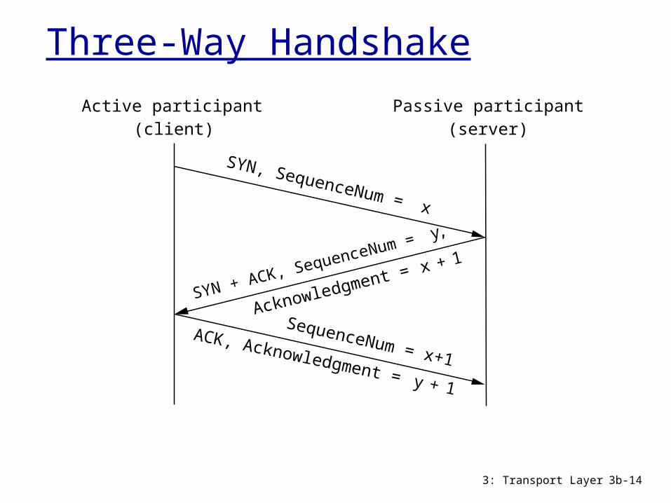
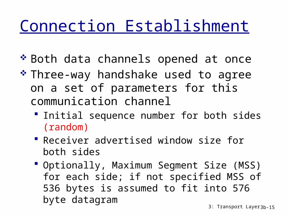
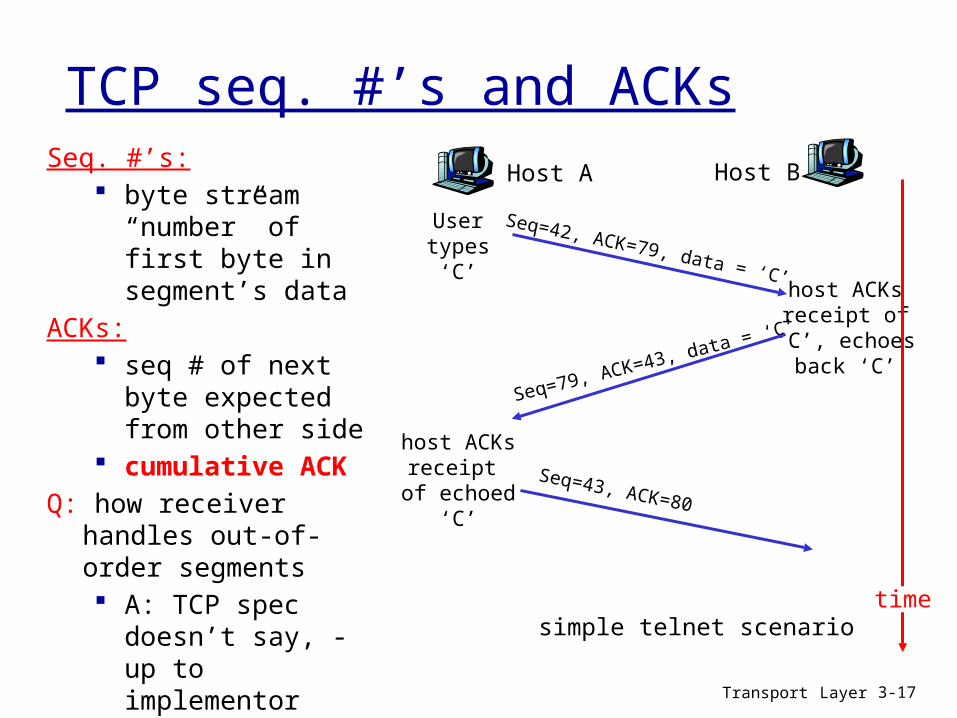
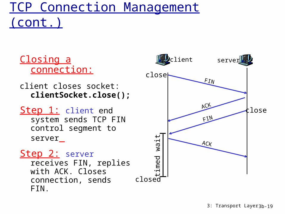
TCP Connection Management (cont)
Closing a connection
client closes socket clientSocketclose()
Step 1 client end system sends TCP FIN control segment to server
Step 2 server receives FIN replies with ACK Closes connection sends FIN
3 Transport Layer 3b-19
client
FIN
server
ACK
ACK
FIN
close
close
closed
tim
ed w
ait
Transport Layer 3-20
Chapter 3 outline
31 Transport-layer services32 Multiplexing and demultiplexing33 Connectionless transport UDP34 Principles of reliable data transfer
35 Connection-oriented transport TCP segment structure reliable data transfer flow control connection
management
36 Principles of congestion control
37 TCP congestion control
Transport Layer 3-21
TCP reliable data transfer
TCP creates rdt service on top of IPrsquos unreliable service
pipelined segments cumulative acks TCP uses single retransmission timer
retransmissions are triggered by timeout events duplicate acks
initially consider simplified TCP sender ignore duplicate acks ignore flow control congestion control
Transport Layer 3-22
TCP Quiz -2
What are ldquoCumulative Acksrdquo What is advantage of having short time outs What is advantage of having long time outs Describe the method(s) TCP uses to detect
packet losses What is Fast Retransmit
Transport Layer 3-23
TCP sender eventsdata rcvd from app Create segment with
seq seq is byte-stream
number of first data byte in segment
start timer if not already running (think of timer as for oldest unacked segment)
expiration interval TimeOutInterval
timeout retransmit segment
that caused timeout restart timer Ack rcvd If acknowledges
previously unacked segments update what is known
to be acked start timer if there are
outstanding segments
Transport Layer 3-24
TCP sender(simplified)
NextSeqNum = InitialSeqNum SendBase = InitialSeqNum
loop (forever) switch(event)
event data received from application above create TCP segment with sequence number NextSeqNum if (timer currently not running) start timer pass segment to IP NextSeqNum = NextSeqNum + length(data)
event timer timeout retransmit not-yet-acknowledged segment with smallest sequence number start timer
event ACK received with ACK field value of y if (y gt SendBase) SendBase = y if (there are currently not-yet-acknowledged segments) start timer
end of loop forever
Commentbull SendBase-1 last cumulatively acked byteExamplebull SendBase-1 = 71
y= 73 so the rcvrwants 73+ y gt SendBase sothat new data is acked
TCP retransmission scenarios
Host A
Seq=100 20 bytes data
ACK=100
time
premature timeout
Host B
Seq=92 8 bytes data
ACK=120
Seq=92 8 bytes data
Seq=
92
tim
eout
ACK=120
Host A
Seq=92 8 bytes data
ACK=100
loss
tim
eout
lost ACK scenario
Host B
X
Seq=92 8 bytes data
ACK=100
time
Seq=
92
tim
eout
SendBase= 100
SendBase= 120
SendBase= 120
SendBase= 100
Transport Layer 3-26
TCP retransmission scenarios (more)
Host A
Seq=92 8 bytes data
ACK=100
loss
tim
eout
Cumulative ACK scenario
Host B
X
Seq=100 20 bytes data
ACK=120
time
SendBase= 120
Transport Layer 3-27
TCP Round Trip Time and TimeoutQ how to set TCP
timeout value longer than RTT
but RTT varies too short
premature timeout unnecessary
retransmissions too long slow
reaction to segment loss
Q how to estimate RTT SampleRTT measured time
from segment transmission until ACK receipt ignore retransmissions
SampleRTT will vary want estimated RTT ldquosmootherrdquo average several recent
measurements not just current SampleRTT
Transport Layer 3-28
TCP Round Trip Time and TimeoutEstimatedRTT = (1- )EstimatedRTT + SampleRTT
Exponential weighted moving average influence of past sample decreases exponentially
fast typical value = 0125
Transport Layer 3-29
Example RTT estimationRTT gaiacsumassedu to fantasiaeurecomfr
100
150
200
250
300
350
1 8 15 22 29 36 43 50 57 64 71 78 85 92 99 106
time (seconnds)
RTT
(mill
isec
onds
)
SampleRTT Estimated RTT
Transport Layer 3-30
Fast Retransmit
time-out period often relatively long long delay before resending lost packet
detect lost segments via duplicate ACKs sender often sends many segments back-to-back if segment is lost there will likely be many duplicate
ACKs
if sender receives 3 ACKs for the same data it supposes that segment after ACKed data was lost fast retransmit resend
segment before timer expires
Transport Layer 3-31
Host A
tim
eout
Host B
time
X
resend 2nd segment Seq=100 20 bytes data
Figure 337 Resending a segment after triple duplicate ACK
Seq=92 8 bytes data
ACK=100
Seq=100 20 bytes data
ACK=100
ACK=100
ACK=100
Seq=120 20 bytes dataSeq=140 20 bytes dataSeq=160 20 bytes data
ACK=180
Transport Layer 3-32
Chapter 3 outline
31 Transport-layer services32 Multiplexing and demultiplexing33 Connectionless transport UDP34 Principles of reliable data transfer
35 Connection-oriented transport TCP segment structure reliable data transfer flow control connection
management
36 Principles of congestion control
37 TCP congestion control
Transport Layer 3-33
TCP Flow Control
receive side of TCP connection has a receive buffer
speed-matching service matching the send rate to the receiving apprsquos drain rate
app process may be slow at reading from buffer
sender wonrsquot overflow
receiverrsquos buffer bytransmitting too
much too fast
flow control
Transport Layer 3-34
TCP Flow control how it works
(suppose TCP receiver discards out-of-order segments)
spare room in buffer= RcvWindow= RcvBuffer-[LastByteRcvd -
LastByteRead]
rcvr advertises spare room by including value of RcvWindow in segments
sender limits unACKed data to RcvWindow guarantees receive
buffer doesnrsquot overflow
Transport Layer 3-35
Chapter 3 outline
31 Transport-layer services32 Multiplexing and demultiplexing33 Connectionless transport UDP34 Principles of reliable data transfer
35 Connection-oriented transport TCP segment structure reliable data transfer flow control connection
management
36 Principles of congestion control
37 TCP congestion control
Transport Layer 3-36
TCP Connection Management
Recall TCP sender receiver establish ldquoconnectionrdquo before exchanging data segments
initialize TCP variables seq s buffers flow control
info (eg RcvWindow) client connection
initiator Socket clientSocket = new
Socket(hostnameport
number) server contacted by
client Socket connectionSocket =
welcomeSocketaccept()
Three way handshake
Step 1 client host sends TCP SYN segment to server specifies initial seq no data
Step 2 server host receives SYN replies with SYNACK segment server allocates buffers specifies server initial
seq Step 3 client receives
SYNACK replies with ACK segment which may contain data
Transport Layer 3-37
TCP Connection Management (cont)
Closing a connection
client closes socket clientSocketclose()
Step 1 client end system sends TCP FIN control segment to server
Step 2 server receives FIN replies with ACK Closes connection sends FIN
client
FIN
server
ACK
ACK
FIN
close
close
closed
tim
ed w
ait
Transport Layer 3-38
TCP Connection Management (cont)
Step 3 client receives FIN replies with ACK
Enters ldquotimed waitrdquo - will respond with ACK to received FINs
Step 4 server receives ACK Connection closed
client
FIN
server
ACK
ACK
FIN
closing
closing
closed
tim
ed w
ait
closed
Transport Layer 3-39
TCP Connection Management (cont)
TCP clientlifecycle
TCP serverlifecycle
Quiz Why does TCP use time outs How does timeout impact the performance of TCP What are pros and cons for short (long) timeouts How is RTT estimated by TCP What is need for flow control in TCP Describe flow control mechanism What is the primary cause of congestion Mention 3 costs of congestion What is difference between flow and congestion
control
Transport Layer 3-40
Transport Layer 3-41
Chapter 3 outline
31 Transport-layer services32 Multiplexing and demultiplexing33 Connectionless transport UDP34 Principles of reliable data transfer
35 Connection-oriented transport TCP segment structure reliable data transfer flow control connection
management
36 Principles of congestion control
37 TCP congestion control
Transport Layer 3-42
Principles of Congestion Control
Congestion informally ldquotoo many sources sending too
much data too fast for network to handlerdquo different from flow control manifestations
lost packets (buffer overflow at routers) long delays (queueing in router buffers)
a top-10 problem
Transport Layer 3-43
Causescosts of congestion scenario 1
two senders two receivers
one router infinite buffers
no retransmission
large delays when congested
maximum achievable throughput
unlimited shared output link buffers
Host Alin original data
Host B
lout
lin original data
lout
Transport Layer 3-44
Causescosts of congestion scenario 2 one router finite buffers sender retransmission of timed-out packet
application-layer input = application-layer output lin = lout
transport-layer input includes retransmissions lin lin
finite shared output link buffers
Host A
lin original data
Host B
loutlin original data plus
retransmitted data
lsquo
Transport Layer 3-45
Congestion scenario 2a ideal case sender sends
only when router buffers available
finite shared output link buffers
Host A
lin original data
Host B
loutlin original data plus
retransmitted data
copy
R2
R2lin
l out
free buffer space
Transport Layer 3-46
Host A
lin original data
Host B
loutlin original data plus
retransmitted data
copy
no buffer space
packets may get dropped at router due to full buffers sometimes lost
sender only resends if packet known to be lost (admittedly idealized)
Congestion scenario 2b known loss
Transport Layer 3-47
Congestion scenario 2b known loss
Host A
lin original data
Host B
loutlin original data plus
retransmitted data
free buffer space
packets may get dropped at router due to full buffers sometimes not lost
sender only resends if packet known to be lost (admittedly idealized)
R2
R2lin
l out
when sending at R2 some packets are retransmissions but asymptotic goodput is still R2
Transport Layer 3-48
packets may get dropped at router due to full buffers
sender times out prematurely sending two copies both of which are delivered
Host A
lin
Host B
loutlincopy
free buffer space
Congestion scenario 2c duplicates
timeout
R4
R4lin
l out
Transport Layer 3-49
packets may get dropped at router due to full buffers
sender times out prematurely sending two copies both of which are delivered
Congestion scenario 2c duplicates
ldquocostsrdquo of congestion more work (retrans) for given ldquogoodputrdquo unneeded retransmissions link carries multiple copies of
pkt decreasing goodput
R4
R4lin
l out
Transport Layer 3-50
Causescosts of congestion scenario 3 four senders multihop paths timeoutretransmit
lin
Q what happens as and increase
lin
finite shared output link buffers
Host Alin original data
Host B
lout
lin original data plus retransmitted data
Transport Layer 3-51
Causescosts of congestion scenario 3
another ldquocostrdquo of congestion when packet dropped any ldquoupstream
transmission capacity used for that packet was wasted
Host A
Host B
lo
u
t
Transport Layer 3-52
Approaches towards congestion control
end-end congestion control
no explicit feedback from network
congestion inferred from end-system observed loss delay
approach taken by TCP
network-assisted congestion control
routers provide feedback to end systems single bit indicating
congestion (SNA DECbit TCPIP ECN ATM)
explicit rate sender should send at
Two broad approaches towards congestion control
Transport Layer 3-53
Chapter 3 outline
31 Transport-layer services32 Multiplexing and demultiplexing33 Connectionless transport UDP34 Principles of reliable data transfer
35 Connection-oriented transport TCP segment structure reliable data transfer flow control connection
management
36 Principles of congestion control
37 TCP congestion control
Transport Layer 3-54
TCP congestion control additive increase multiplicative decrease
approach increase transmission rate (window size) probing for usable bandwidth until loss occurs additive increase increase cwnd by 1 MSS
every RTT until loss detected multiplicative decrease cut cwnd in half after
loss
8 Kbytes
16 Kbytes
24 Kbytes
time
congestionwindow
time
cwnd
con
gest
ion
win
dow
siz
e
saw toothbehavior probing
for bandwidth
Transport Layer 3-55
TCP Congestion Control details
sender limits transmission
LastByteSent-LastByteAcked cwnd roughly
cwnd is dynamic function of perceived network congestion
How does sender perceive congestion
loss event = timeout or 3 duplicate acks
TCP sender reduces rate (cwnd) after loss event
three mechanisms AIMD slow start conservative after
timeout events
rate = cwnd
RTT Bytessec
Transport Layer 3-56
TCP Slow Start
when connection begins increase rate exponentially until first loss event initially cwnd = 1 MSS double cwnd every RTT done by incrementing cwnd for every ACK received
summary initial rate is slow but ramps up exponentially fast
Host A
one segment
RTT
Host B
time
two segments
four segments
Transport Layer 3-57
Refinement inferring loss
after 3 dup ACKs cwnd is cut in half window then grows
linearly but after timeout event
cwnd instead set to 1 MSS
window then grows exponentially
to a threshold then grows linearly
3 dup ACKs indicates network capable of delivering some segments
timeout indicates a ldquomore alarmingrdquo congestion scenario
Philosophy
Transport Layer 3-58
Refinement
Q when should the exponential increase switch to linear
A when cwnd gets to 12 of its value before timeout
Implementation variable ssthresh on loss event ssthresh
is set to 12 of cwnd just before loss event
Can you identify different phases
Connection Timeline
3 Transport Layer 3b-59
Transport Layer 3-60
Summary TCP Congestion Control
timeoutssthresh = cwnd2
cwnd = 1 MSSdupACKcount = 0
retransmit missing segment
Lcwnd gt ssthresh
congestionavoidance
cwnd = cwnd + MSS (MSScwnd)dupACKcount = 0
transmit new segment(s) as allowed
new ACK
dupACKcount++
duplicate ACK
fastrecovery
cwnd = cwnd + MSStransmit new segment(s) as allowed
duplicate ACK
ssthresh= cwnd2cwnd = ssthresh + 3
retransmit missing segment
dupACKcount == 3
timeoutssthresh = cwnd2cwnd = 1 dupACKcount = 0retransmit missing segment
ssthresh= cwnd2cwnd = ssthresh + 3retransmit missing segment
dupACKcount == 3cwnd = ssthreshdupACKcount = 0
New ACK
slow start
timeoutssthresh = cwnd2
cwnd = 1 MSSdupACKcount = 0
retransmit missing segment
cwnd = cwnd+MSSdupACKcount = 0transmit new segment(s) as allowed
new ACKdupACKcount++
duplicate ACK
Lcwnd = 1 MSS
ssthresh = 64 KBdupACKcount = 0
NewACK
NewACK
NewACK
Transport Layer 3-61
TCP throughput
whatrsquos the average throughout of TCP as a function of window size and RTT ignore slow start
let W be the window size when loss occurs when window is W throughput is WRTT just after loss window drops to W2
throughput to W2RTT average throughout 75 WRTT
Transport Layer 3-62
TCP Futures TCP over ldquolong fat pipesrdquo
example 1500 byte segments 100ms RTT want 10 Gbps throughput
requires window size W = 83333 in-flight segments
throughput in terms of loss rate
L = 210-10 Wow ndash a very small loss rate new versions of TCP for high-speed
LRTT
MSS221
Transport Layer 3-63
fairness goal if K TCP sessions share same bottleneck link of bandwidth R each should have average rate of RK
TCP connection 1
bottleneckrouter
capacity R
TCP connection 2
TCP Fairness
Transport Layer 3-64
TCP is fair
two competing sessions additive increase gives slope of 1 as throughout increases multiplicative decrease decreases throughput proportionally
R
R
equal bandwidth share
Connection 1 throughputConnect
ion 2
th
roughput
congestion avoidance additive increaseloss decrease window by factor of 2
congestion avoidance additive increaseloss decrease window by factor of 2
Transport Layer 3-65
Fairness (more)
Fairness and UDP multimedia apps
often do not use TCP do not want rate
throttled by congestion control
instead use UDP pump audiovideo at
constant rate tolerate packet loss
Fairness and parallel TCP connections
nothing prevents app from opening parallel connections between 2 hosts
web browsers do this example link of rate R
supporting 9 connections new app asks for 1 TCP
gets rate R10 new app asks for 11 TCPs
gets R2
Transport Layer 3-66
Chapter 3 Summary principles behind
transport layer services multiplexing
demultiplexing reliable data transfer flow control congestion control
instantiation and implementation in the Internet UDP TCP
Next leaving the
network ldquoedgerdquo (application transport layers)
into the network ldquocorerdquo
Netstat
netstat ndasha ndashn Shows open connections in various states Example
Active Connections
Proto LocalAddr ForeignAddr StateTCP 000023 00000 LISTENINGTCP 1921680100139 2072008922580 CLOSE_WAITTCP 19216801001275 12832449622 ESTABLISHEDUDP 1270011070
Quiz
What are three primary mechanisms of TCP Congestion Control
What are the two TCP loss events How many packets are transmitted in
the first 4 RTT durations after a TCP connection is established
Transport Layer 3-68
Quiz (cont)
Transport Layer 3-69
- Slide 1
- Chapter 3 outline
- TCP Overview RFCs 793 1122 1323 2018 2581
- TCP segment structure
- TCP segment structure - Quiz
- TCP Header Flags (6 bits)
- TCP Header ACK flag
- TCP Header PUSH
- TCP Header Header Length
- Implications of Field Length
- Implications of Field Length (cont)
- TCP Header Common Options
- TCP Connection Management
- Three-Way Handshake
- Connection Establishment
- Initial Sequence Numbers
- TCP seq rsquos and ACKs
- Connection Termination
- TCP Connection Management (cont)
- Chapter 3 outline (2)
- TCP reliable data transfer
- TCP Quiz -2
- TCP sender events
- TCP sender (simplified)
- TCP retransmission scenarios
- TCP retransmission scenarios (more)
- TCP Round Trip Time and Timeout
- TCP Round Trip Time and Timeout (2)
- Example RTT estimation
- Fast Retransmit
- Slide 31
- Chapter 3 outline (3)
- TCP Flow Control
- TCP Flow control how it works
- Chapter 3 outline (4)
- TCP Connection Management (2)
- TCP Connection Management (cont) (2)
- TCP Connection Management (cont) (3)
- TCP Connection Management (cont)
- Quiz
- Chapter 3 outline (5)
- Principles of Congestion Control
- Causescosts of congestion scenario 1
- Causescosts of congestion scenario 2
- Congestion scenario 2a ideal case
- Congestion scenario 2b known loss
- Congestion scenario 2b known loss (2)
- Congestion scenario 2c duplicates
- Congestion scenario 2c duplicates (2)
- Causescosts of congestion scenario 3
- Causescosts of congestion scenario 3 (2)
- Approaches towards congestion control
- Chapter 3 outline (6)
- TCP congestion control additive increase multiplicative decre
- TCP Congestion Control details
- TCP Slow Start
- Refinement inferring loss
- Refinement
- Connection Timeline
- Summary TCP Congestion Control
- TCP throughput
- TCP Futures TCP over ldquolong fat pipesrdquo
- TCP Fairness
- TCP is fair
- Fairness (more)
- Chapter 3 Summary
- Netstat
- Quiz (2)
- Quiz (cont)
-
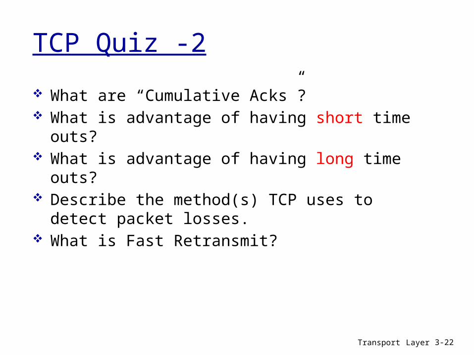
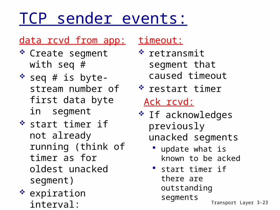
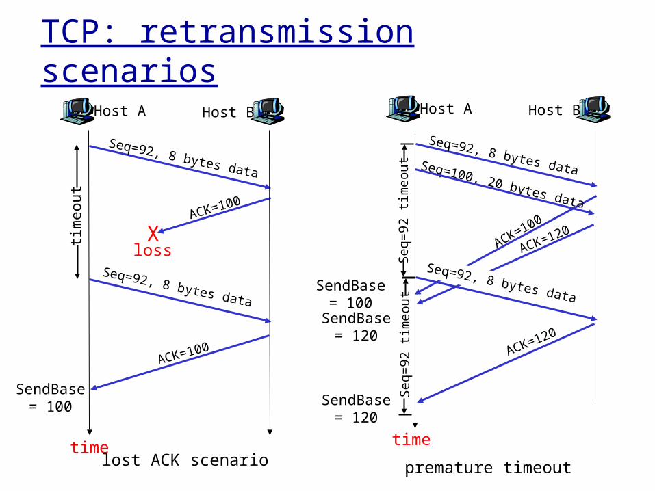
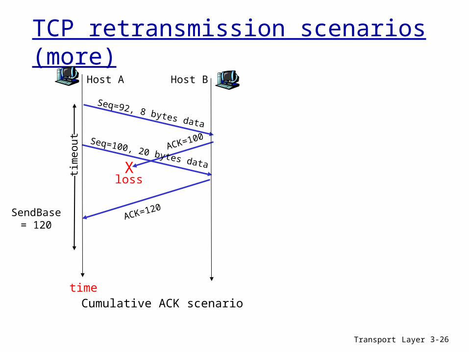
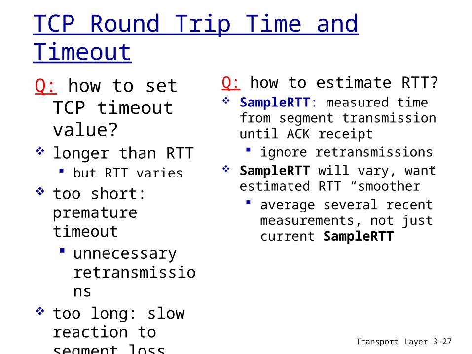
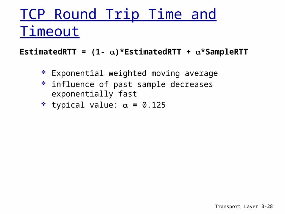
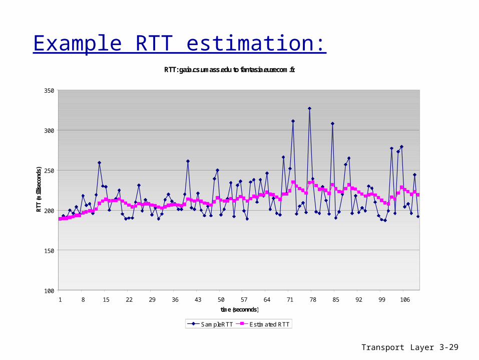
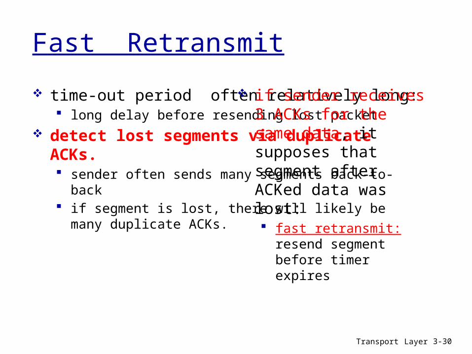
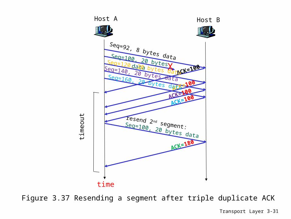
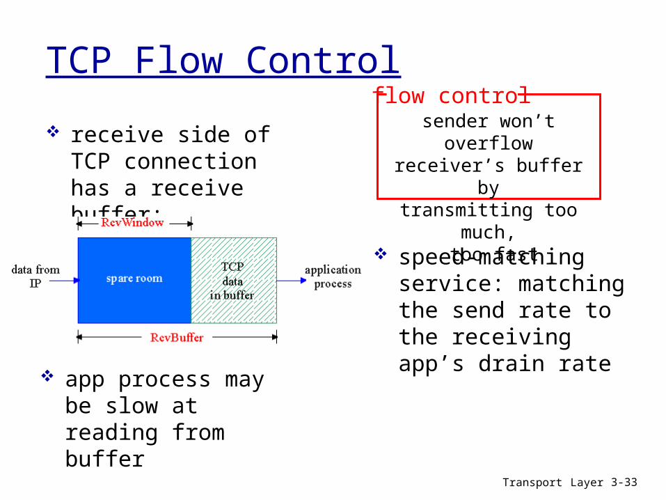
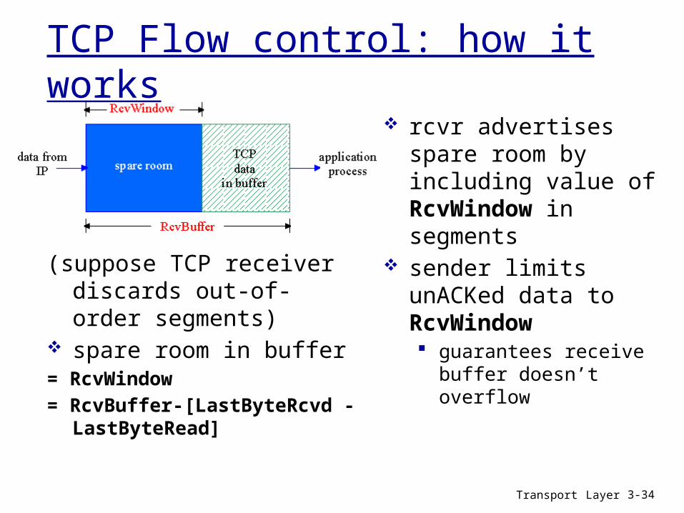
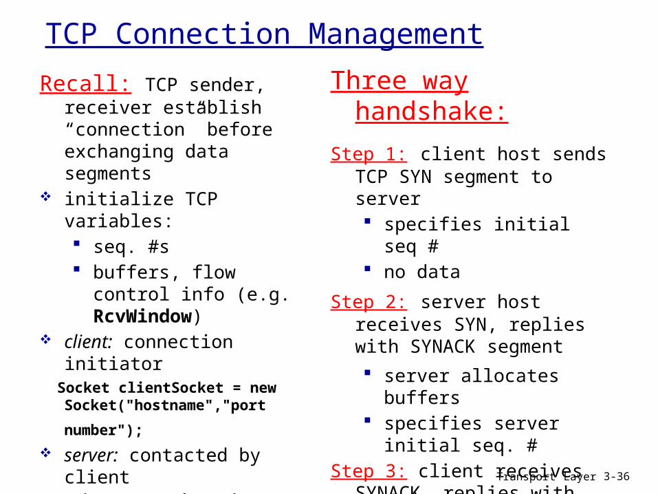
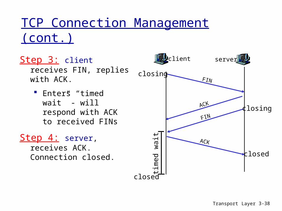
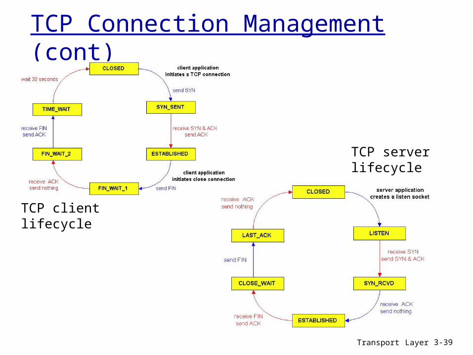
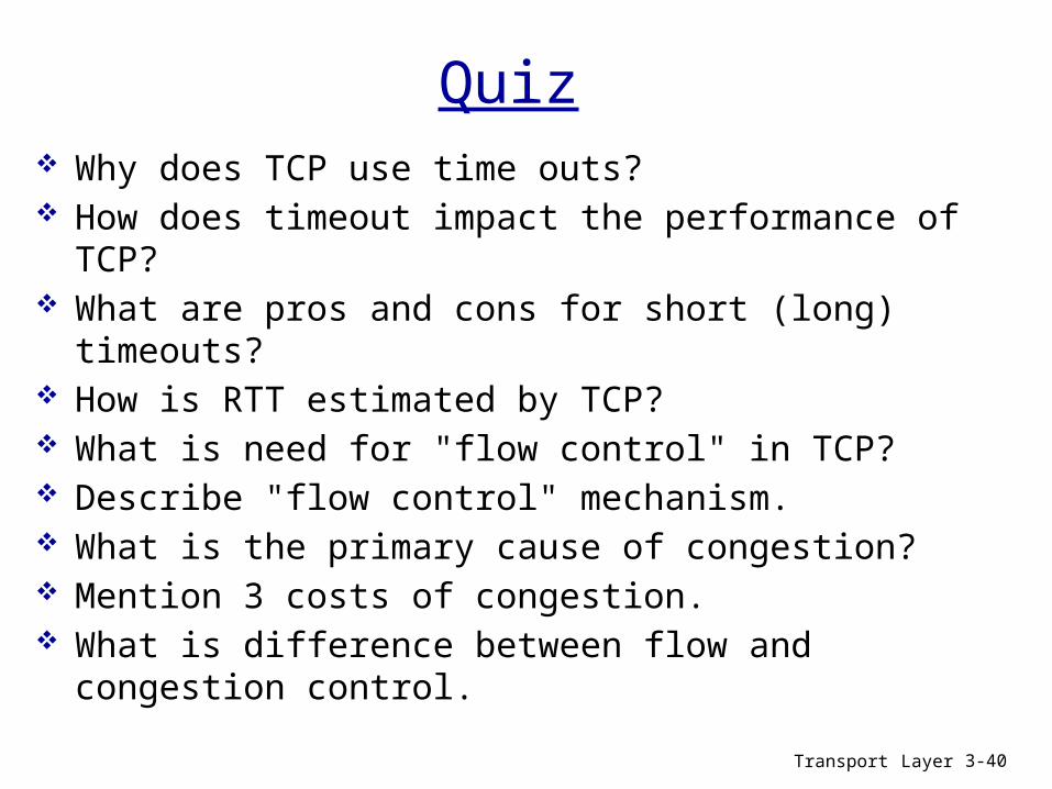
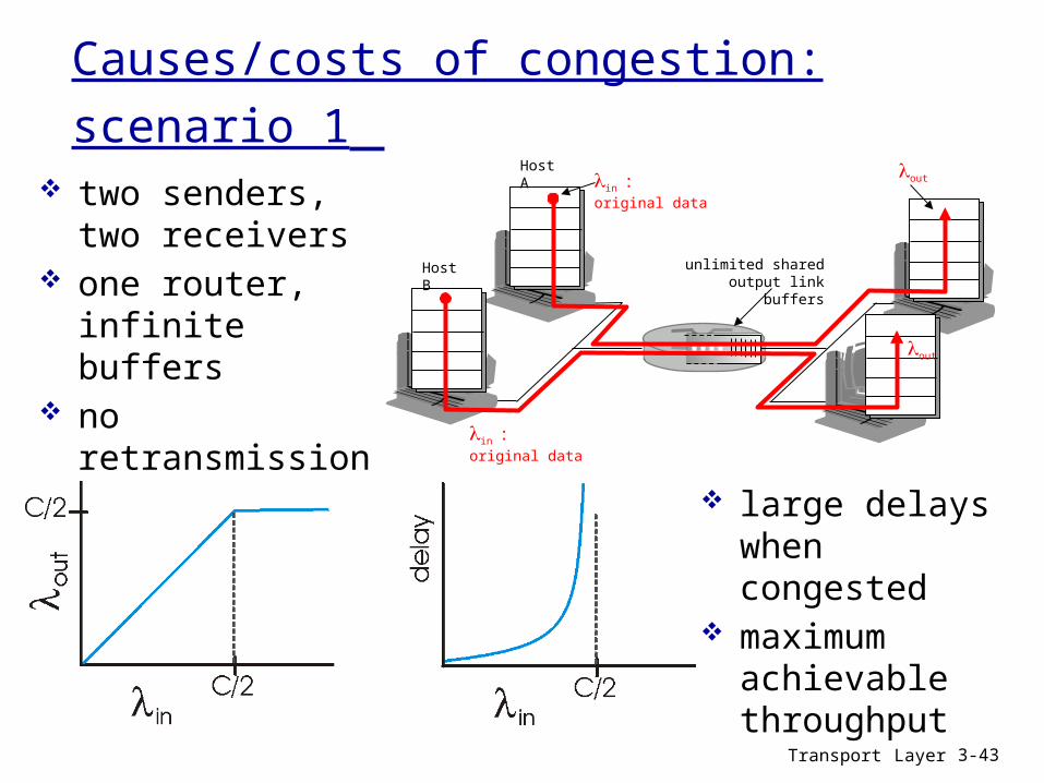
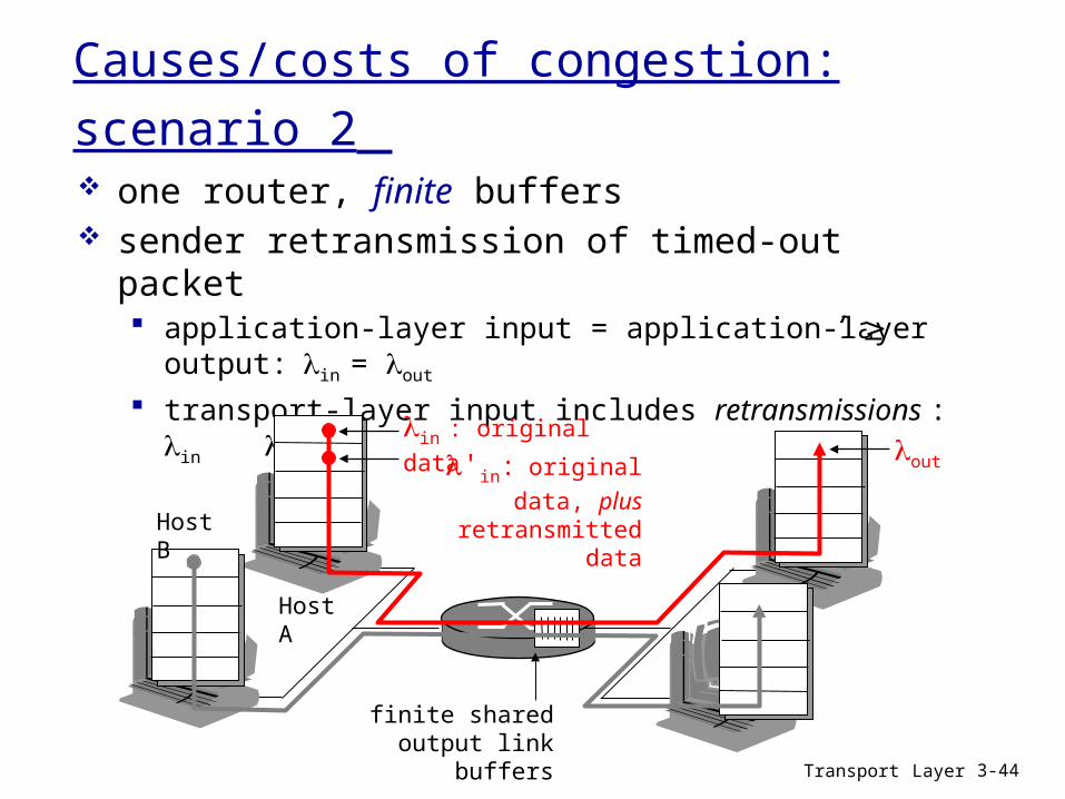
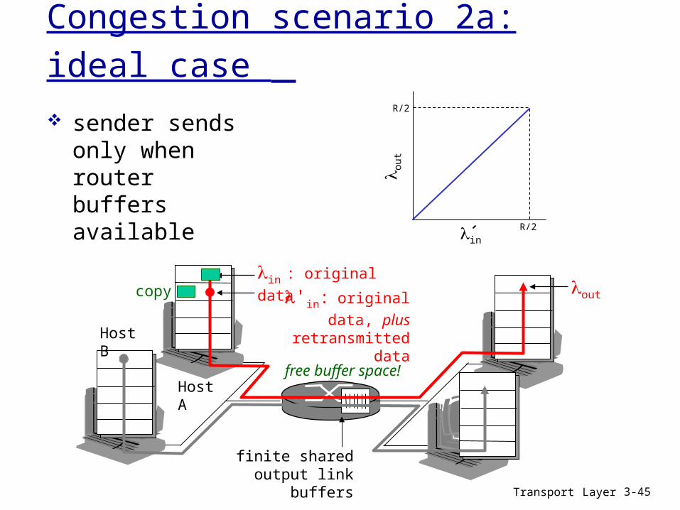
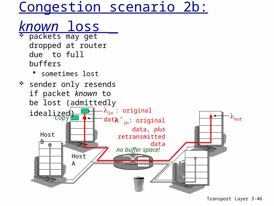
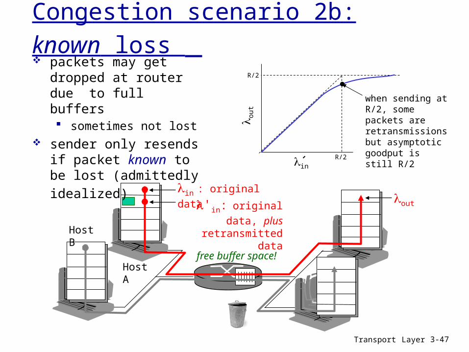
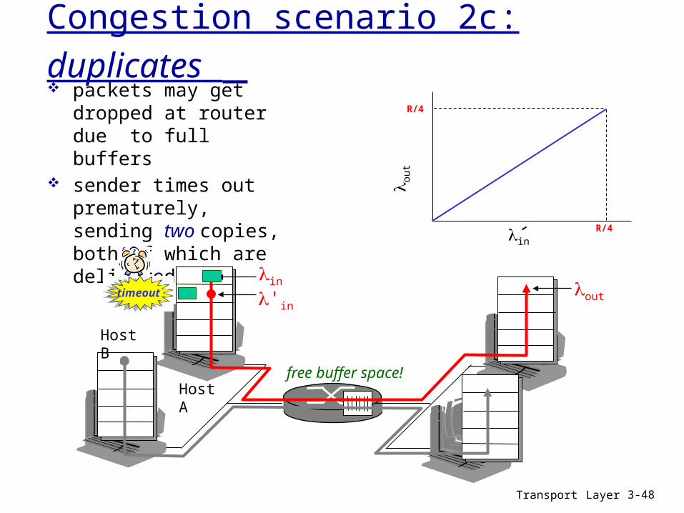
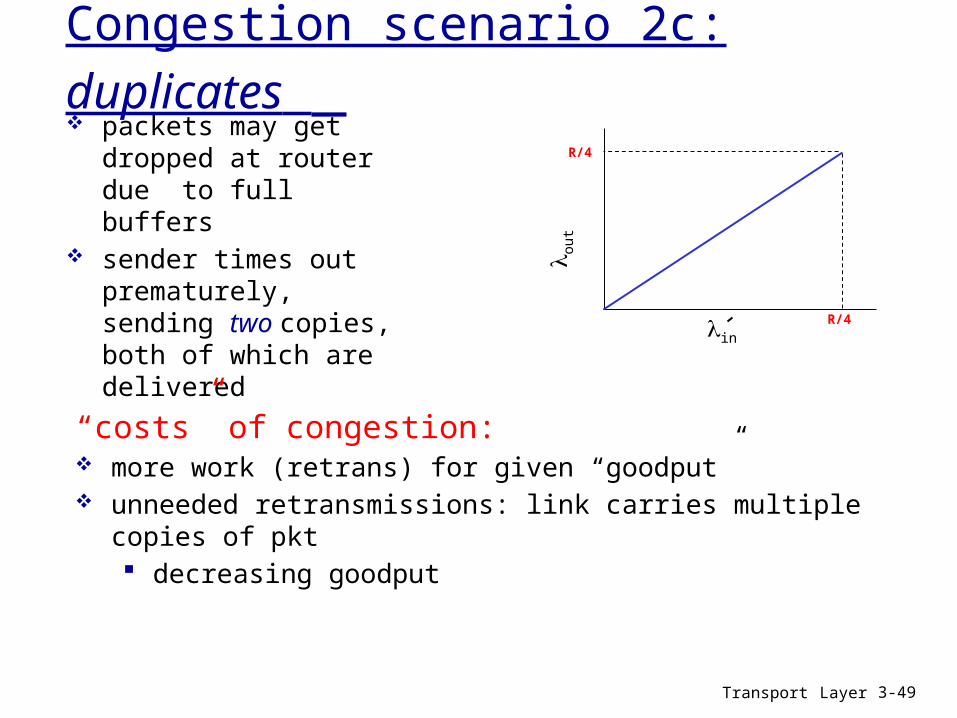
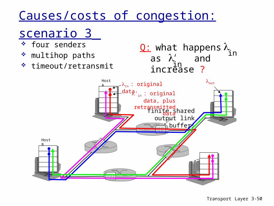
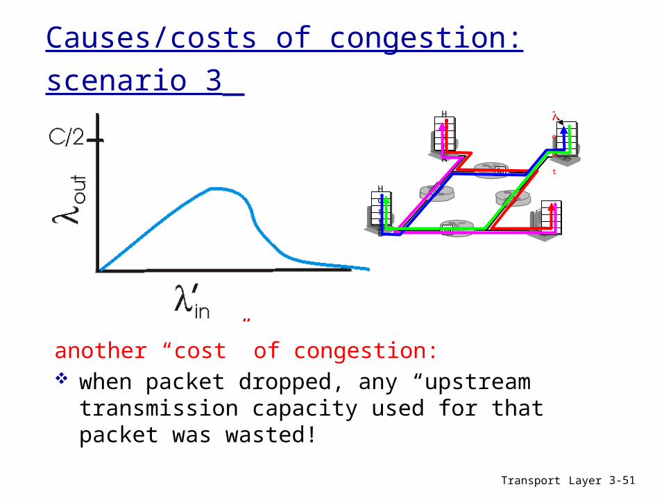
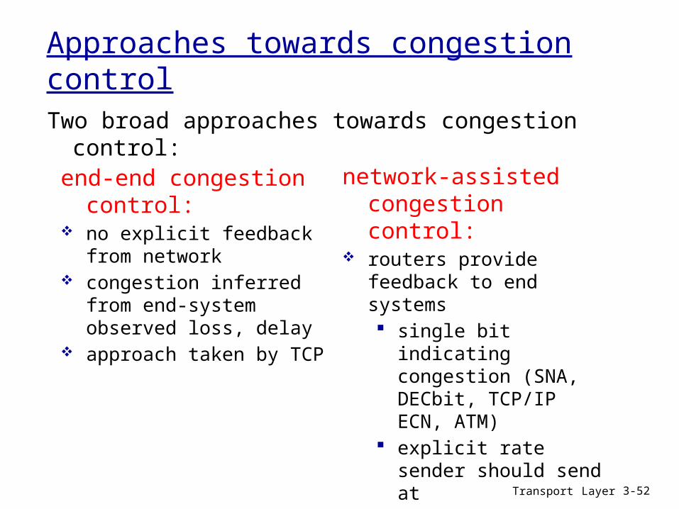
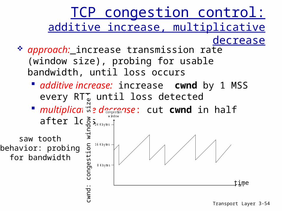
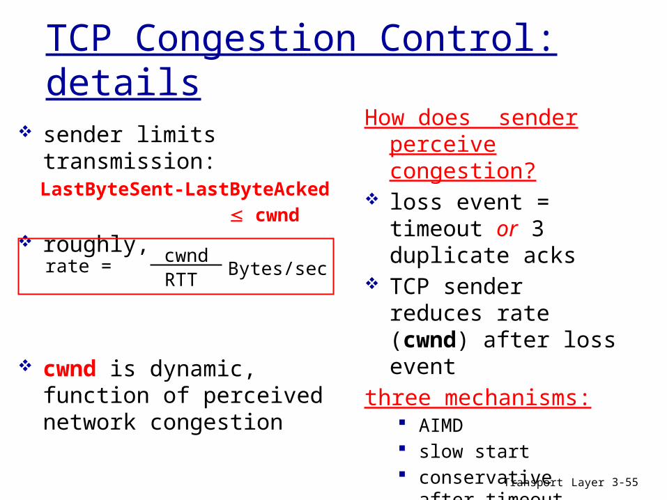
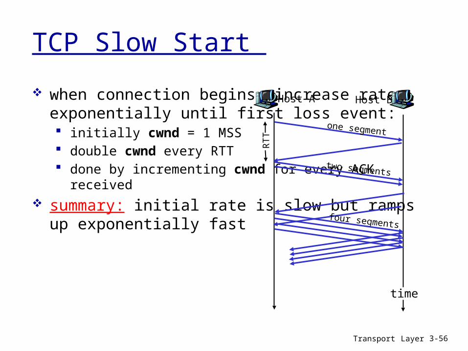
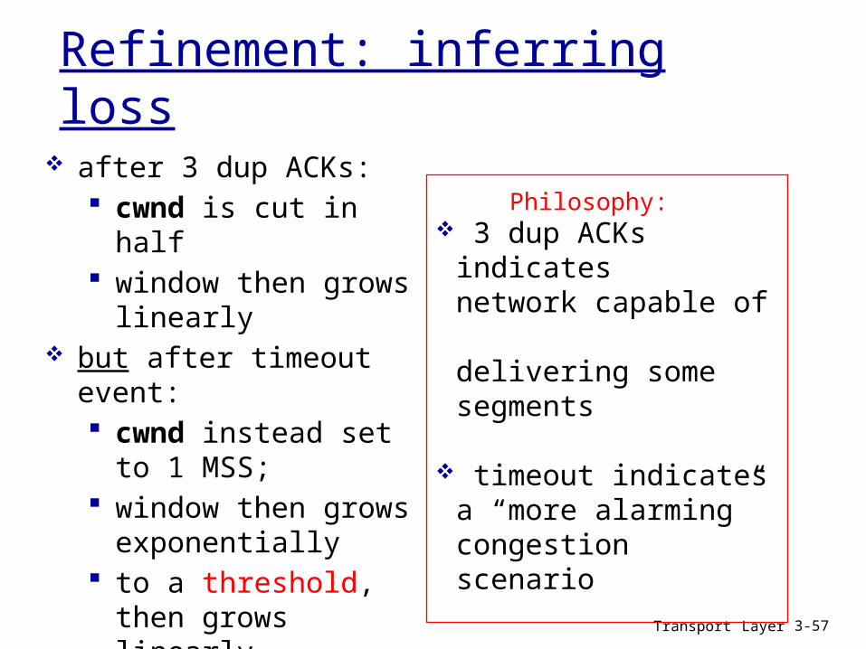
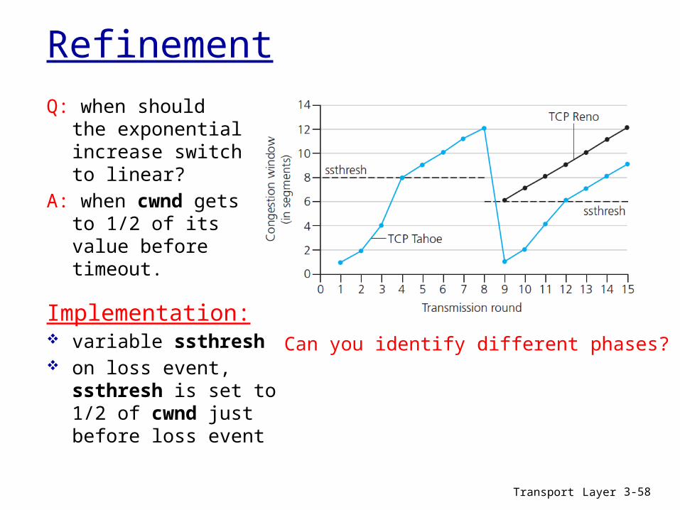
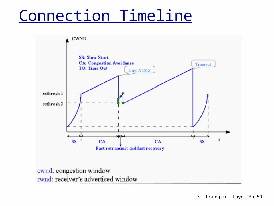
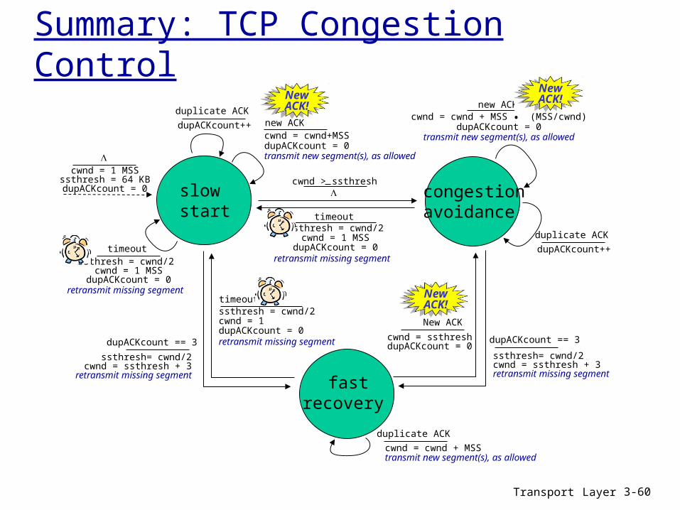
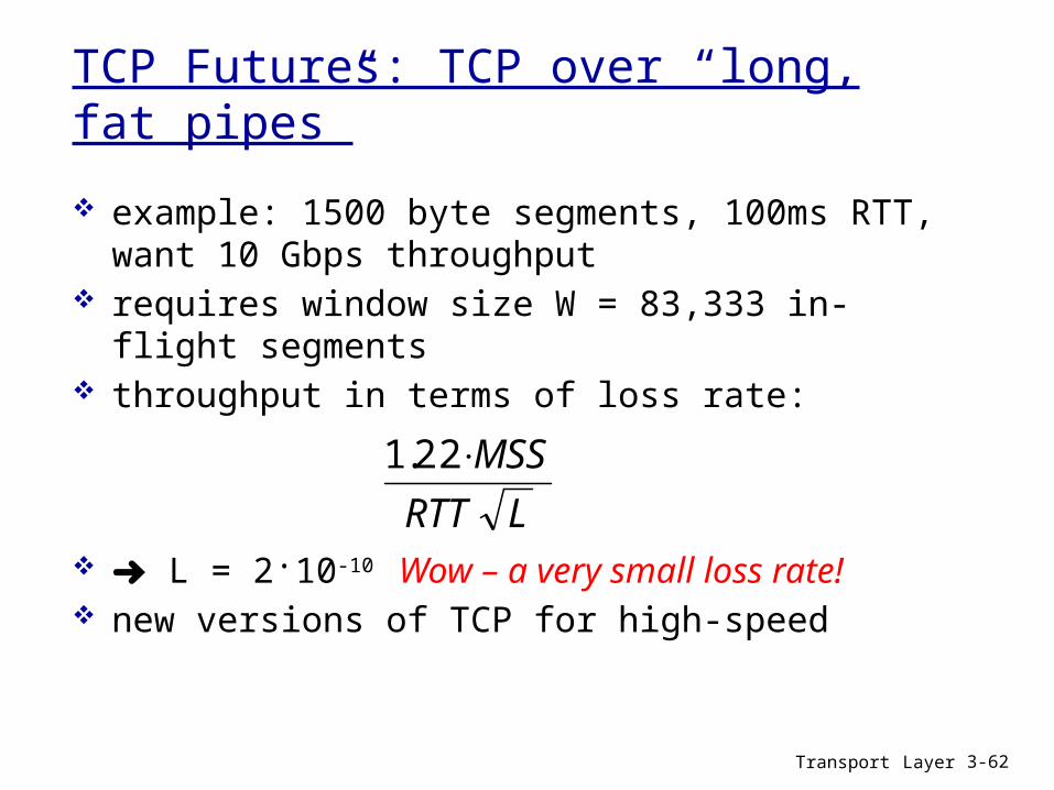
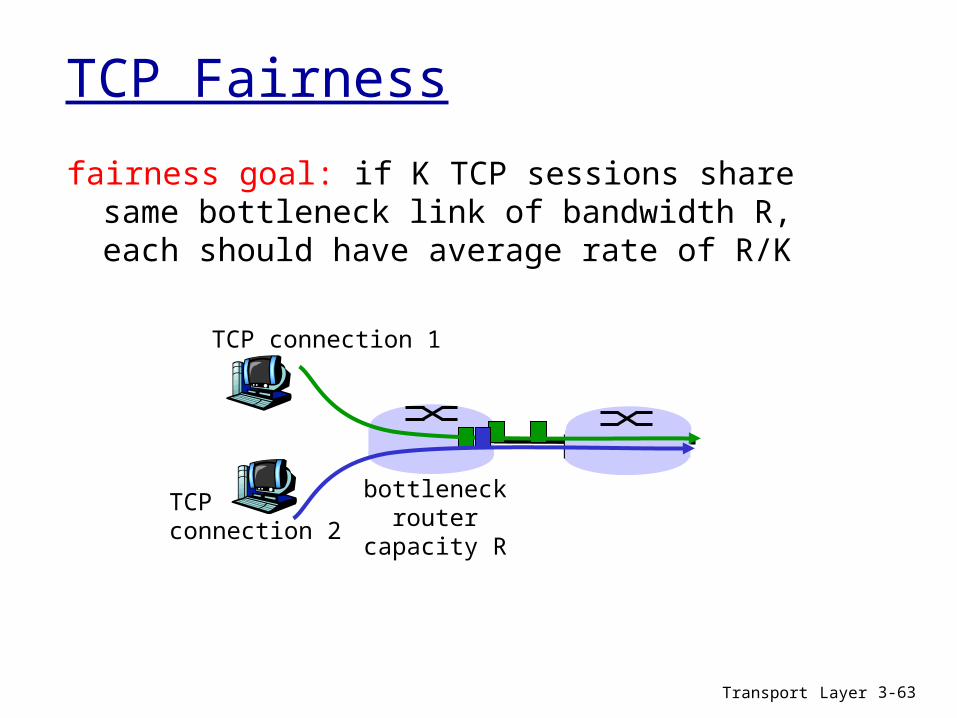
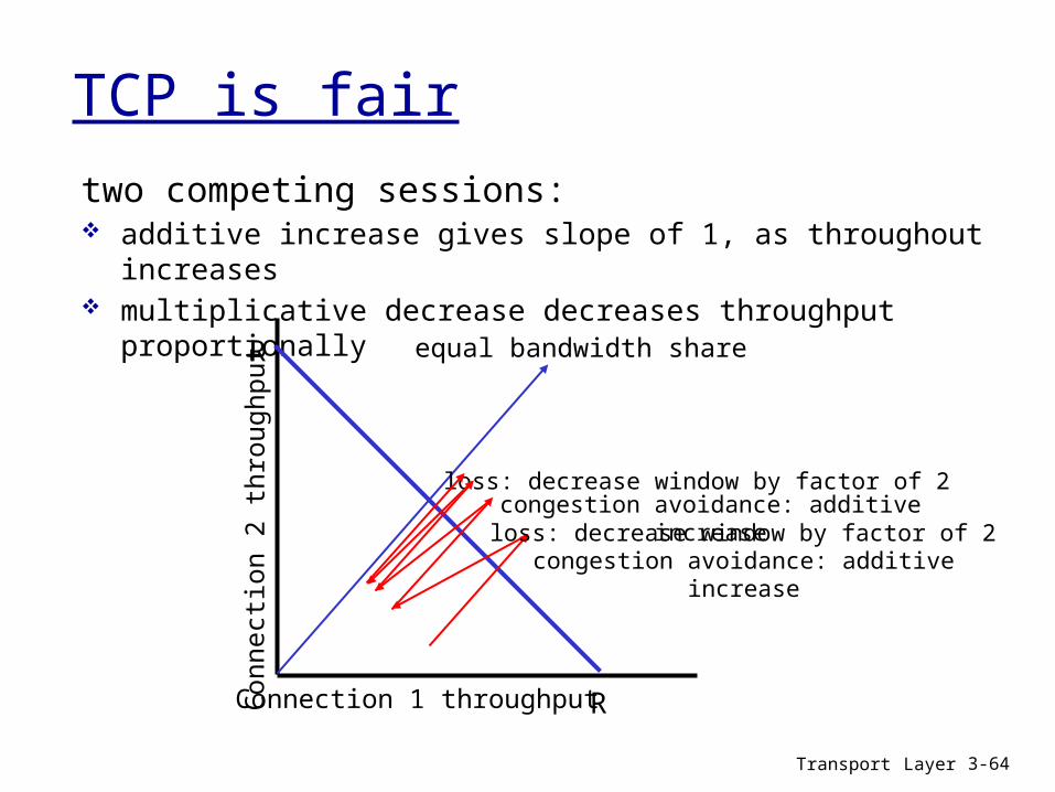