CSC384: Intro to Artificial Intelligencesengels/csc258/lectures/Devices_1up.pdf · CSC258 Lecture...
20
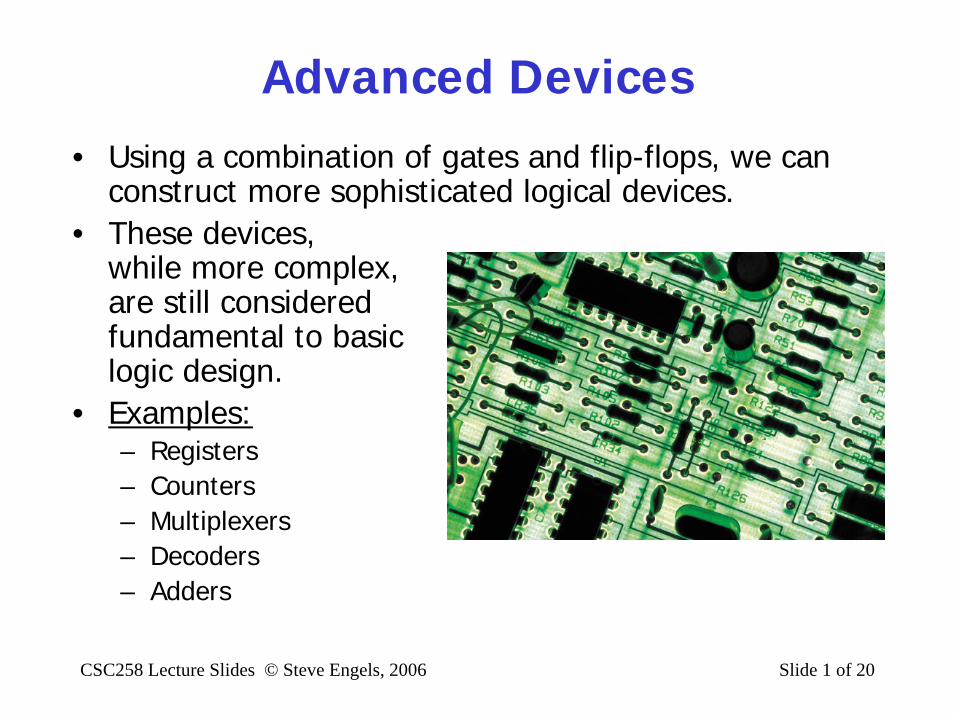
CSC258 Lecture Slides © Steve Engels, 2006 Slide 1 of 20 Advanced Devices • Using a combination of gates and flip-flops, we can construct more sophisticated logical devices. • These devices, while more complex, are still considered fundamental to basic logic design. • Examples: – Registers – Counters – Multiplexers – Decoders – Adders
Transcript of CSC384: Intro to Artificial Intelligencesengels/csc258/lectures/Devices_1up.pdf · CSC258 Lecture...
CSC258 Lecture Slides © Steve Engels, 2006 Slide 1 of 20
Advanced Devices• Using a combination of gates and flip-flops, we can
construct more sophisticated logical devices.• These devices,
while more complex,are still consideredfundamental to basiclogic design.
• Examples:– Registers– Counters– Multiplexers– Decoders– Adders

CSC258 Lecture Slides © Steve Engels, 2006 Slide 2 of 20
Registers
• Storing single bits in a flip-flop is nice, but to store data values such as integers and doubles, you need to store 32 or 64 bits at a time.
• Registers are several flip-flops that have been arranged together to store values like these.
• Example: simple shift register
D Q
Q
D Q
Q
D Q
Q
D Q
Q
F0 F1 F2 F3OutXin
Read/WriteClock

CSC258 Lecture Slides © Steve Engels, 2006 Slide 3 of 20
Shift Registers
D Q
Q
D Q
Q
D Q
Q
D Q
Q
Xin
F3
Read/WriteClock
F2 F1 F0Out
• Shift registers load a value into the individual bits by loading them on the input line, from least significant to most significant.
• Reading from a shift register is also done in the same way.
• Flip-flops (master-slave) are appropriate here, not simple gated latches.

CSC258 Lecture Slides © Steve Engels, 2006 Slide 4 of 20
Parallel Registers
• The number of clock cycles consumed by a load or read operation in a shift registers is the same as the number of bits in the register itself time-consuming
• Instead, try loading and reading bits in parallel (see diagram)
• Saves on time, butconsumes more gate resources.
• Commonly used,despite the expense.

CSC258 Lecture Slides © Steve Engels, 2006 Slide 5 of 20
Register Operations
• How would you use a 4-bit register to divide a given integer in half? What signals would you have to send, and in what order?
• First step: What does it mean to divide a binary number in half?
D3D2D1D0
Q3Q2Q1Q0
Shift/LoadSerial input
Clock
4-bit shiftregister
parallel input parallel output

CSC258 Lecture Slides © Steve Engels, 2006 Slide 6 of 20
Register OperationsD3D2D1D0
Q3Q2Q1Q0
Shift/LoadSerial input
Clock
4-bit shiftregister
parallel input parallel output
• Steps for performing divide-by-2:1. Load the given integer into parallel input2. Shift the contents of the register once3. (Read the output)
• Signal sequence:1. D0-D3 input integer, Shift/Load 12. Serial input 0, Shift/Load 0– Output is now ready to be read, until next clock pulse.

CSC258 Lecture Slides © Steve Engels, 2006 Slide 7 of 20
Counters• Registers allow us to store values with flip-flops.
What if we wanted to increment (or decrement) a value, instead of shifting it?
• Counters use flip-flops to store a value, and increment that value if an input signal is high when the clock goes high.
• One possible implementation: Shift Register– Number of flip-flops = max value for counter– Incrementing counter = shifting a 1 value along the chain
Read/WriteD Q
Q
D Q
Q
D Q
Q
D Q
Q
Xin
Fn
Clock
F2 F1 F0Out

CSC258 Lecture Slides © Steve Engels, 2006 Slide 8 of 20
Asynchronous Counters• You didn’t really think that using a shift approach
was a good idea, did you? I really hope not.– Using a shift register would mean that n flip-flops would be
needed to store n possible values!
– C’mon folks, we can do better than that.
• How many bits do you need to store n possible counter values?– Example: A counter that stores 8 possible values.
CSC258 Lecture Slides © Steve Engels, 2006 Slide 9 of 20
Asynchronous Counters
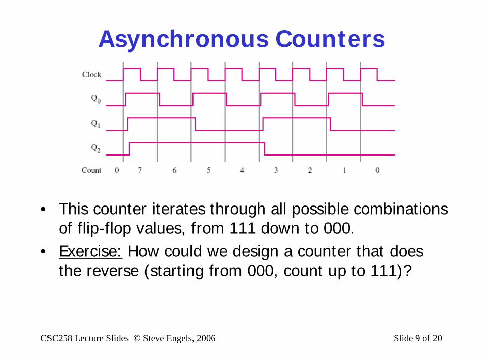
• This counter iterates through all possible combinations of flip-flop values, from 111 down to 000.
• Exercise: How could we design a counter that does the reverse (starting from 000, count up to 111)?

CSC258 Lecture Slides © Steve Engels, 2006 Slide 10 of 20
Synchronous Counters• These counters are considered asynchronous,
because the clock signal is only being used on the first flip-flop. The clock signal of the other flip-flops depends on the output of a previous flip-flop.
• This can cause a slow update speed when the chain of flip-flops becomes very long (e.g. 32 or 64 bits)
• Would be better if all flip-flop’s transitions occurred at the same time as the clock pulse.– Synchronous counters
• How do Q0-Q4 know when to toggle values?

CSC258 Lecture Slides © Steve Engels, 2006 Slide 11 of 20
Synchronous Counters
• To figure out this logic behind this counter, draw a truth table to show when each flip-flop toggles its value.
• Represent these conditionsas the logical input for each flip-flop.
CSC258 Lecture Slides © Steve Engels, 2006 Slide 12 of 20
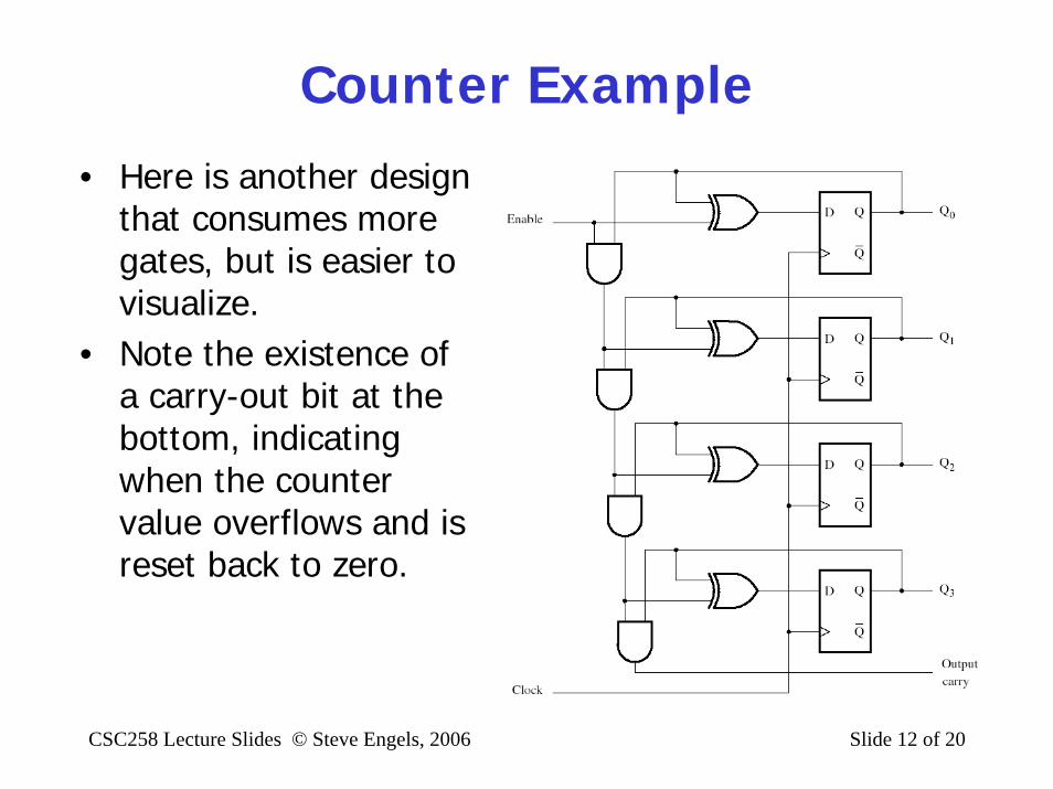
Counter Example
• Here is another design that consumes more gates, but is easier to visualize.
• Note the existence of a carry-out bit at the bottom, indicating when the counter value overflows and is reset back to zero.

CSC258 Lecture Slides © Steve Engels, 2006 Slide 13 of 20
Decoders• As seen with counters, n bits (flip-flops) can be used
to represent 2n different values.– This can be useful when it comes to machine instructions,
where an n-bit word can be used to activate 2n devices.
• A circuit that can translate an n-bit input into one of 2n different output lines is called a decoder.
• The seven-segmentdisplay is an exampleof an application ofdecoders in usefulscenarios.

CSC258 Lecture Slides © Steve Engels, 2006 Slide 14 of 20
Multiplexers• A multiplexer (more commonly known as a mux) is a
device with a single output line, multiple data input lines, and a set of “select” inputs.
• The select lines determine which of the data inputs is channeled to the output.– Therefore the number of select lines needed for any n-input
multiplexer is log n.
• This device is a simple idea, but is one of the more common devices in computer processor design.

CSC258 Lecture Slides © Steve Engels, 2006 Slide 15 of 20
Multiplexers
MUXOut
D0D1D2D3D4D5D6D7
A0 A1 A2
D0
D1
D2
D3
D4
D5
D6
D7
A0A1A2
Out
OutA0A1A2
D7111
…………
D2010
D1100
D0000

CSC258 Lecture Slides © Steve Engels, 2006 Slide 16 of 20
Demultiplexers• Same idea as multiplexers, but in reverse.• Demultiplexers (or
demux) take in a single input, and use the n select bits to determine which of the 2n
output lines this input will be written to.

CSC258 Lecture Slides © Steve Engels, 2006 Slide 17 of 20
Adders
• The function of adders is to add two input digits together, to produce the sum of the digits as output.
• This could be accomplished with a single XOR gate, but we also need to account for other digits being added at the same time.
• In addition to the output indicatingthe sum, a carry-out bit goes to theadder for the next significant digitwhen the inputs are both 1.
• Similarly, a carry-in bit comes fromthe less significant digit as well.

CSC258 Lecture Slides © Steve Engels, 2006 Slide 18 of 20
Adders
Full Adder (FA)
yixi
cout cin
si
• The logic for a single stage of a full adder (aka ripple-carry adder) is shown on the right.
• To perform a parallel addition operation for an n-bit integer, n of these adders need to be chained together in sequence.
• These components can also be used to create other arithmetic operations, in a processor unit called the arithmetic logic unit (ALU).
yixi cin
cout si

CSC258 Lecture Slides © Steve Engels, 2006 Slide 19 of 20
Fast Adder• Sequences of adders suffer from the same
propagation delay issues as asynchronous counters.• Solution: eliminate the
carry-out bit from each unit (also called a half-adder), and add outputs indicating when one or both of the bits are 1.– called generate and
propagate bits.
• Result is a bit-stage cell,or B-cell.
xi
Gi
yi
Pi si
ci

CSC258 Lecture Slides © Steve Engels, 2006 Slide 20 of 20
Fast Adder
B cell
x3 y3
s3G3 P3
c3 B cell
x2 y2
s2G2 P2
c2 B cell
x1 y1
s1G1 P1
c1 B cell
x0 y0
s0G0 P0
c0
Carry-lookahead logic
c4
• The carry term for any cell is:
• Carrying this through, we can expand this:
ci+1 = Gi + PiGi-1 + PiPi-1ci-1
ci+1 = Gi + PiGi-1 + PiPi-1(Gi-2 + Pi-2Gi-3 + Pi-2Pi-3ci-3)