Software Setup GuideSSoftware Setup Guideoftware Setup Guide
Upload
duongthuanCategory
view
218download
3
1
© Jörg Liebeherr, 1998-2003
ATM
© Jörg Liebeherr, 1998-2003
Topics
IntroductionATM Architecture OverviewATM CellATM ConnectionsAddressing and SignalingATM Layer ServicesIP over ATM
2
© Jörg Liebeherr, 1998-2003
Introduction
© Jörg Liebeherr, 1998-2003
Broadband Integrated Services Networks
• In the mid-1980s, the ITU-T (formerly CCITT) initiated a standardization effort to merge voice, video and data on a single network
• The goal was to replace all existing networks (telephony networks, Cable TV network, data networks) with a single network infrastructure. The effort was called B-ISDN (Broadband Integrated Services Digital Networks)
• The technology selected for B-ISDN was Asynchronous Transfer Mode (ATM) and SONET/SDH (Synchronous Optical Network/Synchronous Digital Hierarchy)
3
© Jörg Liebeherr, 1998-2003
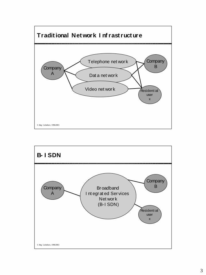
Traditional Network Infrastructure
CompanyA
CompanyB
Telephone network
Data network
Residential user
x
Video network
© Jörg Liebeherr, 1998-2003
B-ISDN
CompanyA
CompanyB
Residential user
x
BroadbandIntegrated Services
Network(B-ISDN)
4
© Jörg Liebeherr, 1998-2003
ATM: The official definition
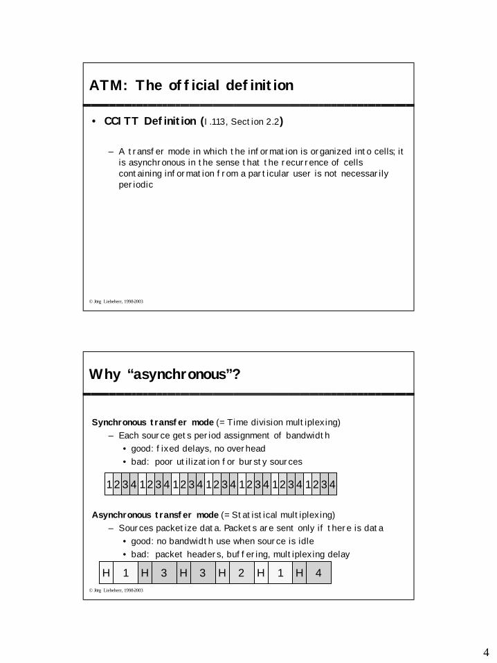
• CCITT Definition (I.113, Section 2.2)
– A transfer mode in which the information is organized into cells; it is asynchronous in the sense that the recurrence of cells containing information from a particular user is not necessarilyperiodic
© Jörg Liebeherr, 1998-2003
Why “asynchronous”?
Synchronous transfer mode (= Time division multiplexing) – Each source gets period assignment of bandwidth
• good: fixed delays, no overhead• bad: poor utilization for bursty sources
Asynchronous transfer mode (= Statistical multiplexing) – Sources packetize data. Packets are sent only if there is data
• good: no bandwidth use when source is idle• bad: packet headers, buffering, multiplexing delay
1 234 1 234 1 234 1 234 1 234 1 234 1 234
1H 3H 3H 2H 1H 4H
5
© Jörg Liebeherr, 1998-2003
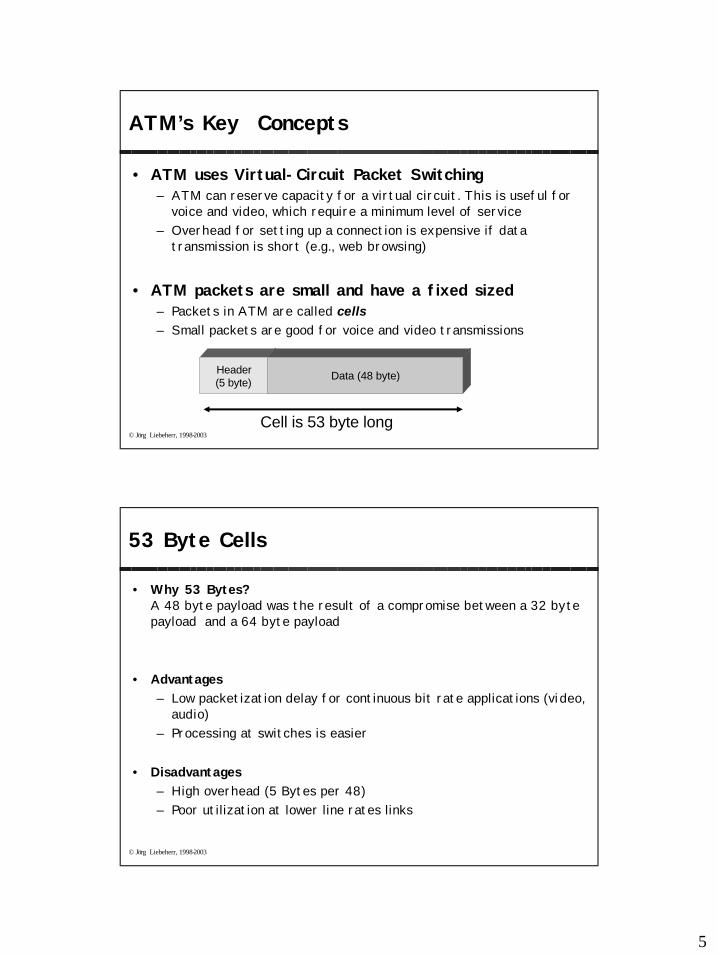
ATM’s Key Concepts
• ATM uses Virtual-Circuit Packet Switching– ATM can reserve capacity for a virtual circuit. This is useful for
voice and video, which require a minimum level of service– Overhead for setting up a connection is expensive if data
transmission is short (e.g., web browsing)
• ATM packets are small and have a fixed sized– Packets in ATM are called cells– Small packets are good for voice and video transmissions
Header(5 byte)
Data (48 byte)
Cell is 53 byte long
© Jörg Liebeherr, 1998-2003
53 Byte Cells
• Why 53 Bytes?A 48 byte payload was the result of a compromise between a 32 byte payload and a 64 byte payload
• Advantages– Low packetization delay for continuous bit rate applications (video,
audio) – Processing at switches is easier
• Disadvantages– High overhead (5 Bytes per 48)– Poor utilization at lower line rates links
6
© Jörg Liebeherr, 1998-2003
ATM Standardization
• Until 1991, standardization occurred within CCITT (now: ITU-T) in a series of recommendations in the I series
• In 1991, ATM Forum was formed as an industry consortium• ATM Forum starts to prepare specifications to accelerate the
definition of ATM. • Specifications are passed to ITU-T for approval• Since 1993, ATM Forum drives the standardization process
• IETF publishes Request for Comments (RFCs) that relate to IP/ATMissues
© Jörg Liebeherr, 1998-2003
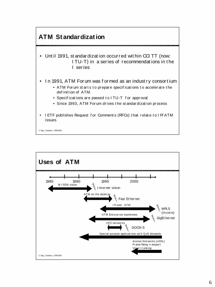
Uses of ATM
1985 1990 1995 2000B-ISDN vision
ATM on the desktop
IP-over- ATM
ATM Enterprise backbones
Fast Ethernet
MPLS (in core)
Internet vision
GigEthernet
Special purpose applications with QoS demands
Access Networks (xDSL)Frame Relay transport Voice trunking
DOCSISHFC networks
7
© Jörg Liebeherr, 1998-2003
ATM ArchitectureOverview
© Jörg Liebeherr, 1998-2003
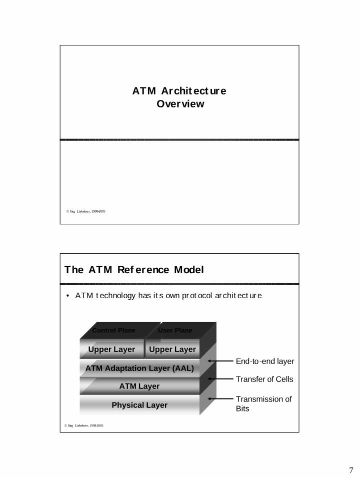
The ATM Reference Model
• ATM technology has its own protocol architecture
Physical Layer
ATM Layer
ATM Adaptation Layer (AAL)
Upper Layer Upper Layer
Control Plane User Plane
Transmission of Bits
Transfer of Cells
End-to-end layer
8
© Jörg Liebeherr, 1998-2003
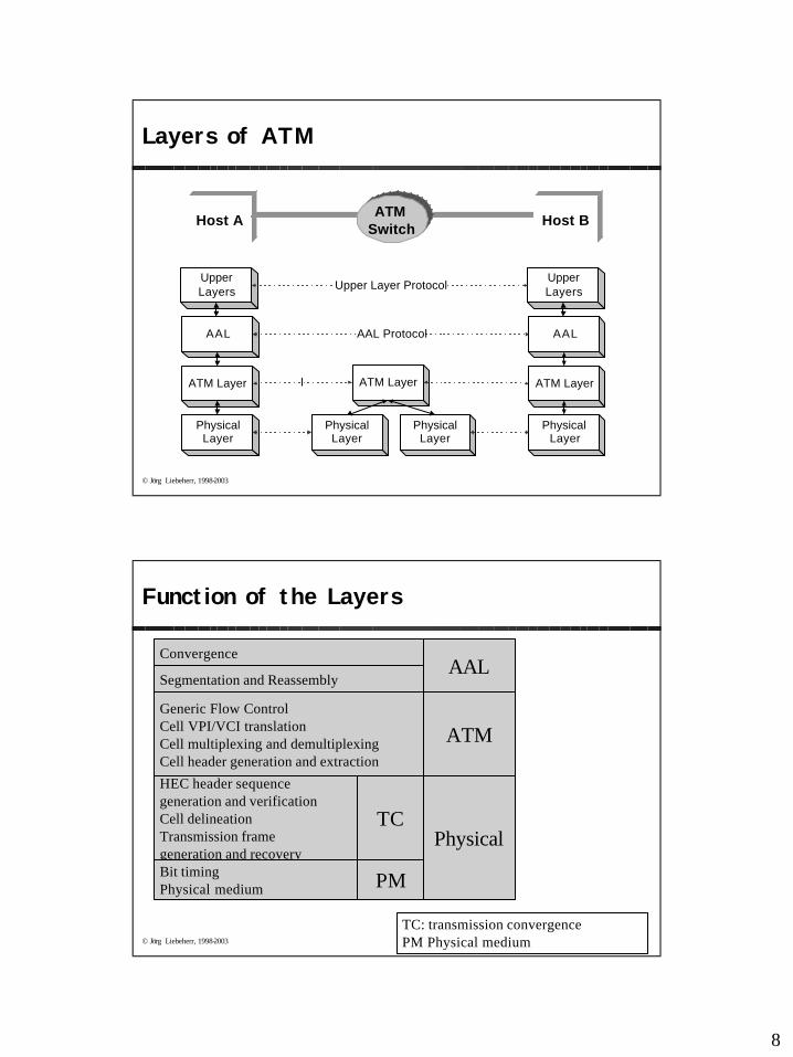
Layers of ATM
AAL
ATM Layer
PhysicalLayer
PhysicalLayer
PhysicalLayer
ATM Layer
AAL
ATM Layer
PhysicalLayer
AAL Protocol
l
UpperLayers
UpperLayersUpper Layer Protocol
Host AATM
SwitchHost B
© Jörg Liebeherr, 1998-2003
Function of the Layers
ConvergenceAAL
Segmentation and Reassembly
Generic Flow ControlCell VPI/VCI translationCell multiplexing and demultiplexingCell header generation and extraction
ATM
HEC header sequence generation and verificationCell delineationTransmission frame generation and recoveryBit timingPhysical medium
TC
PM
Physical
TC: transmission convergencePM Physical medium
9
© Jörg Liebeherr, 1998-2003
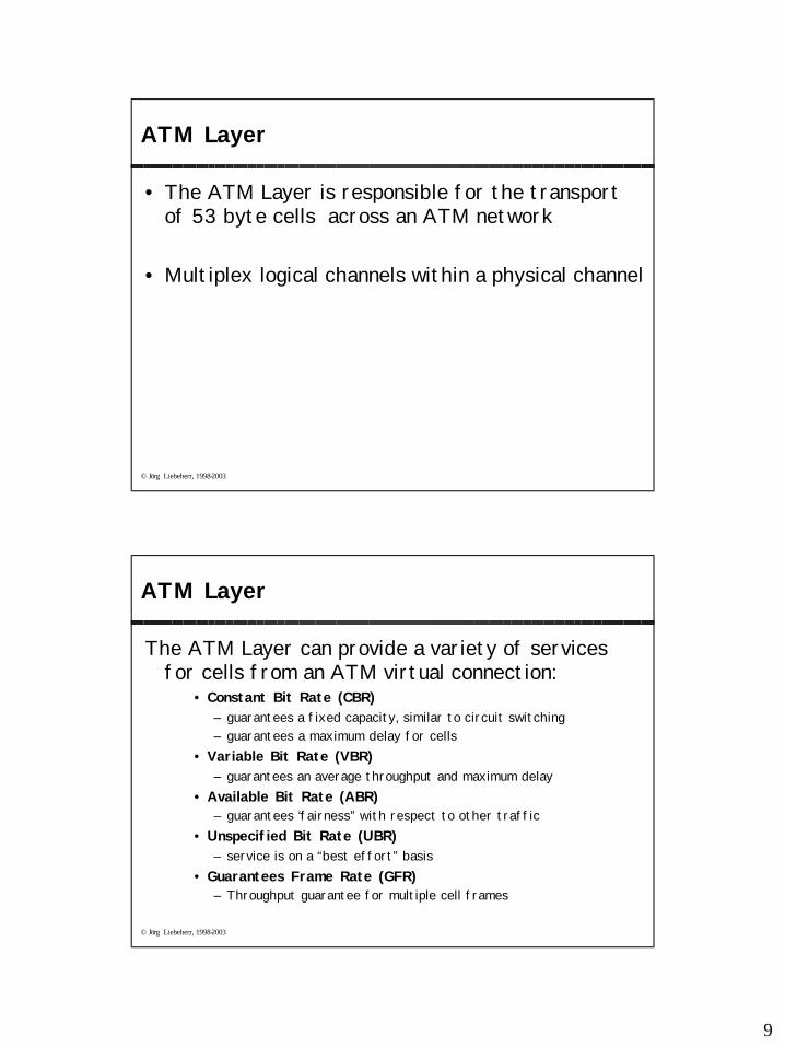
ATM Layer
• The ATM Layer is responsible for the transport of 53 byte cells across an ATM network
• Multiplex logical channels within a physical channel
© Jörg Liebeherr, 1998-2003
ATM Layer
The ATM Layer can provide a variety of services for cells from an ATM virtual connection:
• Constant Bit Rate (CBR)– guarantees a fixed capacity, similar to circuit switching– guarantees a maximum delay for cells
• Variable Bit Rate (VBR)– guarantees an average throughput and maximum delay
• Available Bit Rate (ABR)– guarantees ‘fairness” with respect to other traffic
• Unspecified Bit Rate (UBR)– service is on a “best effort” basis
• Guarantees Frame Rate (GFR)– Throughput guarantee for multiple cell frames
10
© Jörg Liebeherr, 1998-2003
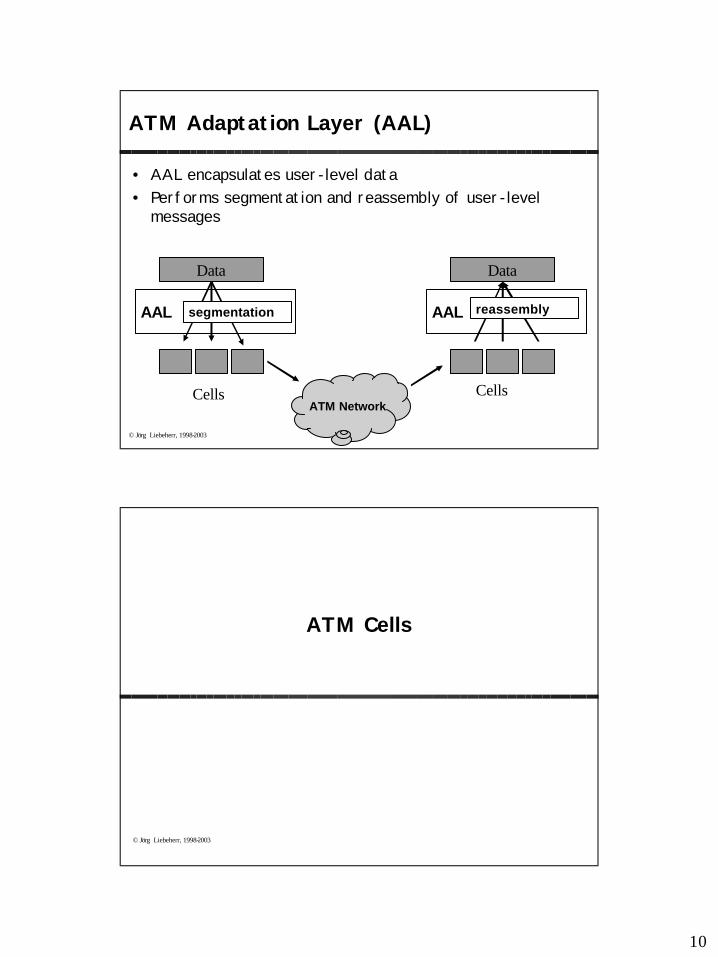
ATM Adaptation Layer (AAL)
• AAL encapsulates user-level data• Performs segmentation and reassembly of user-level
messages
Data
AAL
Data
AAL
Cells CellsATM Network
segmentation reassembly
© Jörg Liebeherr, 1998-2003
ATM Cells
11
© Jörg Liebeherr, 1998-2003
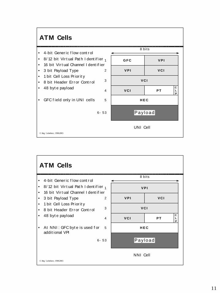
ATM Cells
• 4-bit Generic flow control • 8/12 bit Virtual Path Identifier• 16 bit Virtual Channel Identifier• 3 bit Payload Type• 1 bit Cell Loss Priority• 8 bit Header Error Control• 48 byte payload
• GFC field only in UNI cells
V C I
8 bi ts
G F C V P I
V P I V C I
V C I PTCLP
H E C
1
2
3
4
5
Pay load6 - 53
UNI Cell
© Jörg Liebeherr, 1998-2003
ATM Cells
• 4-bit Generic flow control • 8/12 bit Virtual Path Identifier• 16 bit Virtual Channel Identifier• 3 bit Payload Type• 1 bit Cell Loss Priority• 8 bit Header Error Control• 48 byte payload
• At NNI: GFC byte is used for additional VPI
V C I
8 bi ts
V P I V C I
V C I PTCLP
H E C
1
2
3
4
5
Pay load6 - 53
V P I
NNI Cell
12
© Jörg Liebeherr, 1998-2003
ATM Connections
© Jörg Liebeherr, 1998-2003
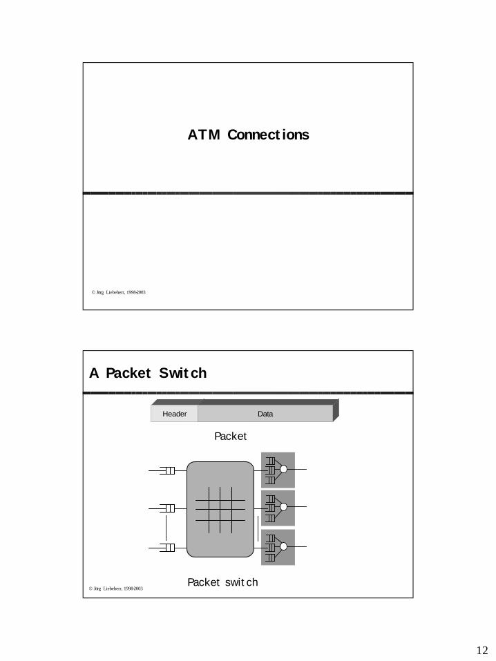
A Packet Switch
Header Data
Packet switch
Packet
13
© Jörg Liebeherr, 1998-2003
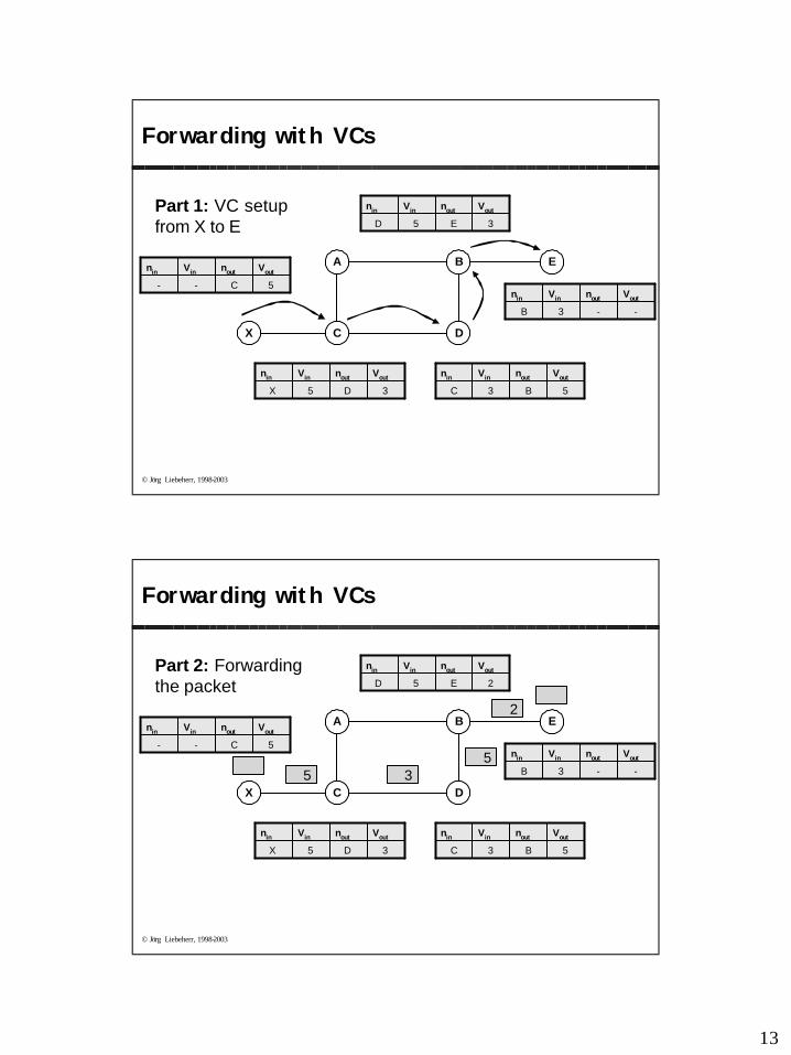
Forwarding with VCs
X
EA
C
B
D
-
Vin
-
nin
5C
Voutnout
5
Vin
X
nin
3D
Voutnout
3
Vin
C
nin
5B
Voutnout
5
Vin
D
nin
3E
Voutnout
3
Vin
B
nin
--
Voutnout
Part 1: VC setup from X to E
© Jörg Liebeherr, 1998-2003
Forwarding with VCs
X
EA
C
B
D
-
Vin
-
nin
5C
Voutnout
5
Vin
X
nin
3D
Voutnout
3
Vin
C
nin
5B
Voutnout
5
Vin
D
nin
2E
Voutnout
3
Vin
B
nin
--
Voutnout
55
3
2
Part 2: Forwarding the packet
14
© Jörg Liebeherr, 1998-2003
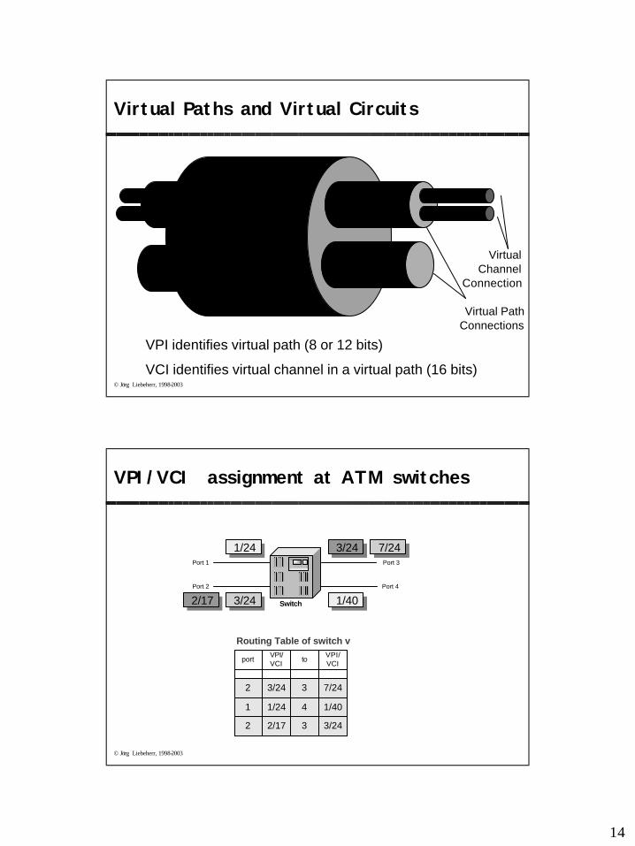
Virtual Paths and Virtual Circuits
Virtual Path Connections
Virtual Channel
Connection
VPI identifies virtual path (8 or 12 bits)
VCI identifies virtual channel in a virtual path (16 bits)
Link
© Jörg Liebeherr, 1998-2003
3/2432/172
7/2433/242
1/4041/241
Routing Table of switch v
port VPI/VCI to VPI/
VCI
Port 1
Port 2
Port 3
Port 4
Switch
VPI/VCI assignment at ATM switches
1/24 7/24
3/24 1/40
3/24
2/17
15
© Jörg Liebeherr, 1998-2003
Addressing and Signaling
© Jörg Liebeherr, 1998-2003
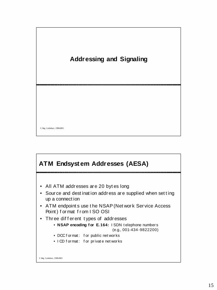
ATM Endsystem Addresses (AESA)
• All ATM addresses are 20 bytes long• Source and destination address are supplied when setting
up a connection• ATM endpoints use the NSAP (Network Service Access
Point) format from ISO OSI• Three different types of addresses
• NSAP encoding for E.164: ISDN telephone numbers (e.g., 001-434-9822200)
• DCC format: for public networks• ICD format: for private networks
16
© Jörg Liebeherr, 1998-2003
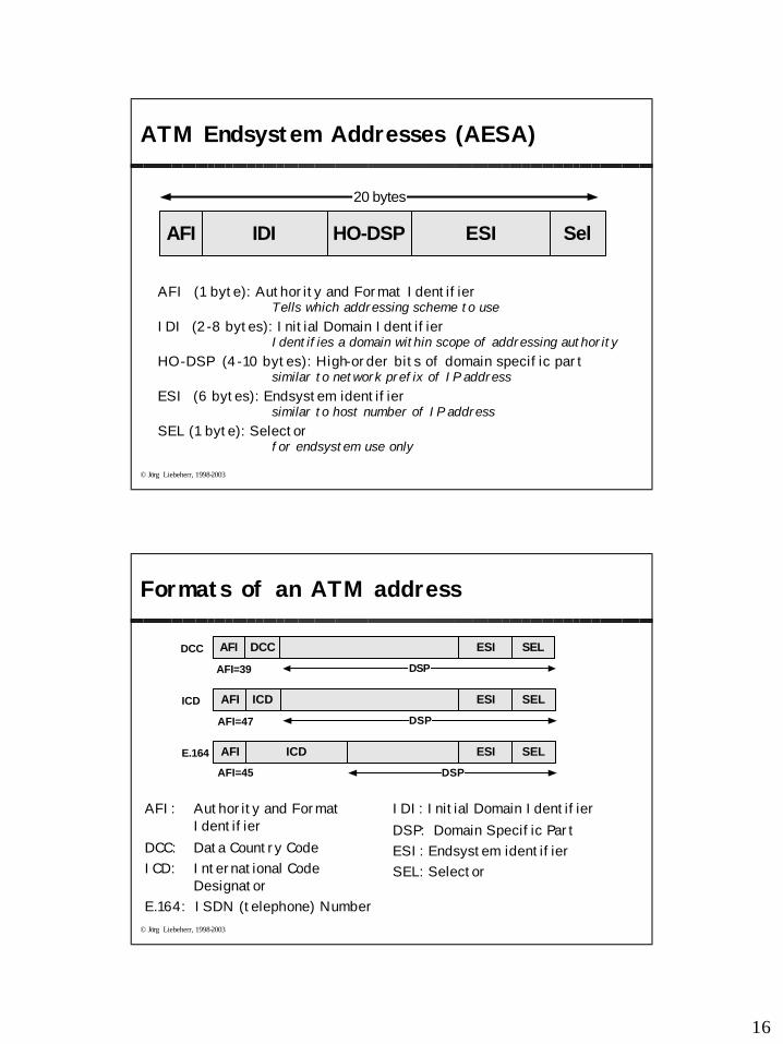
ATM Endsystem Addresses (AESA)
AFI (1 byte): Authority and Format IdentifierTells which addressing scheme to use
IDI (2-8 bytes): Initial Domain IdentifierIdentifies a domain within scope of addressing authority
HO-DSP (4-10 bytes): High-order bits of domain specific partsimilar to network prefix of IP address
ESI (6 bytes): Endsystem identifiersimilar to host number of IP address
SEL (1 byte): Selectorfor endsystem use only
AFI
20 bytes
IDI HO-DSP ESI Sel
© Jörg Liebeherr, 1998-2003
Formats of an ATM address
AFI: Authority and Format Identifier
DCC: Data Country CodeICD: International Code
DesignatorE.164: ISDN (telephone) Number
DSP
AFI DCC ESI SELDCC
AFI=39
DSP
AFI ICD ESI SELICD
AFI=47
DSP
AFI ICD ESI SELE.164
AFI=45
IDI: Initial Domain IdentifierDSP: Domain Specific PartESI: Endsystem identifierSEL: Selector
17
© Jörg Liebeherr, 1998-2003
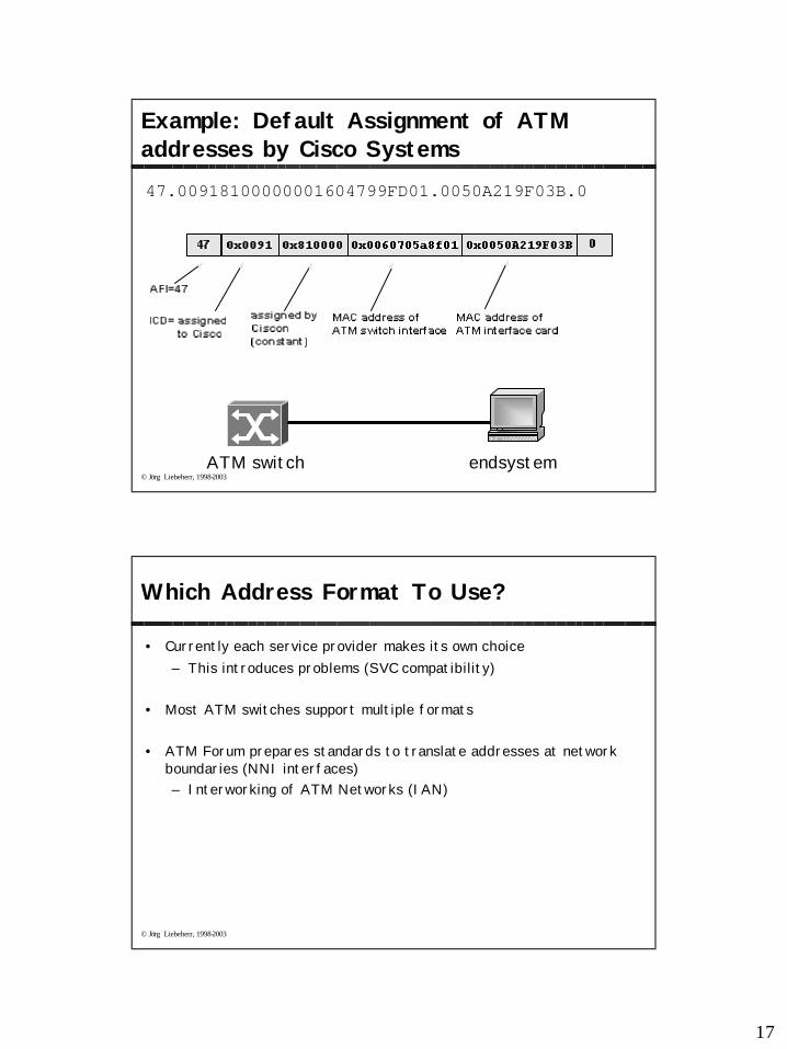
Example: Default Assignment of ATM addresses by Cisco Systems47.00918100000001604799FD01.0050A219F03B.0
ATM switch endsystem
© Jörg Liebeherr, 1998-2003
Which Address Format To Use?
• Currently each service provider makes its own choice– This introduces problems (SVC compatibility)
• Most ATM switches support multiple formats
• ATM Forum prepares standards to translate addresses at network boundaries (NNI interfaces)– Interworking of ATM Networks (IAN)
18
© Jörg Liebeherr, 1998-2003
ATM UNI Signaling
• Significant Signaling Protocols
• ATM Forum:• UNI 3.0. UNI signaling protocol for point-to-point connections. • UNI 3.1. Supports point-to-multipoint connections. • UNI 4.0. Supports Leaf initiated join multipoint connections • PNNI. for network node signaling
• The ATM Forum signaling specifications are based on the Q.2931 public network signaling protocol developed by the ITU-T. – specifies a call control message format
• message type (setup, call proceeding, release)• Addresses• AAL parameters• Quality of Service (QoS)
© Jörg Liebeherr, 1998-2003
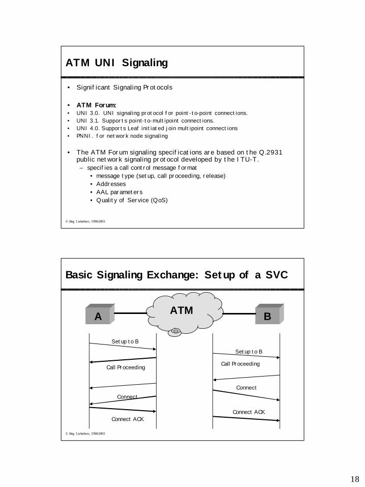
Basic Signaling Exchange: Setup of a SVC
A
Setup to B
Call Proceeding
Setup to B
ConnectConnect
Connect ACKConnect ACK
BATM
Call Proceeding
19
© Jörg Liebeherr, 1998-2003
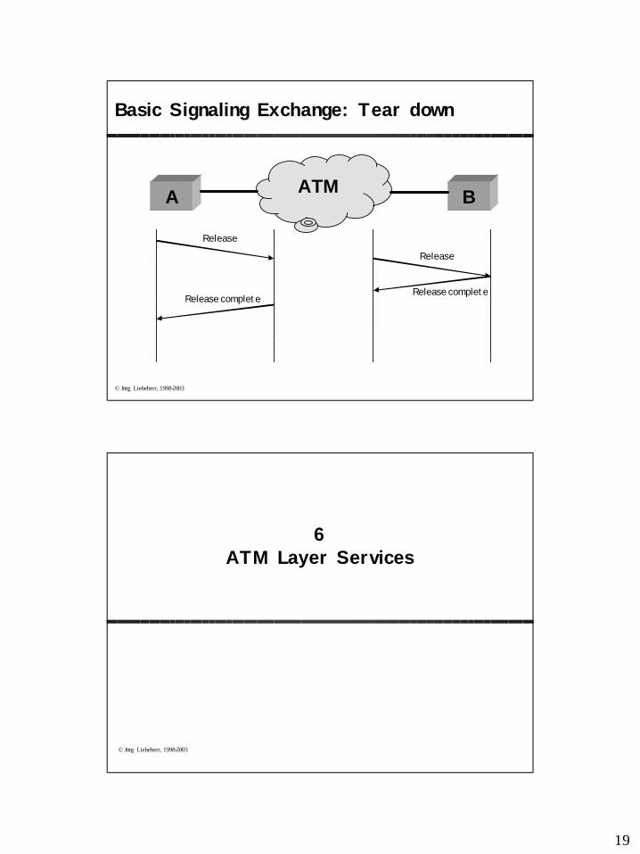
Release
Release
Release completeRelease complete
Basic Signaling Exchange: Tear down
A BATM
© Jörg Liebeherr, 1998-2003
6ATM Layer Services
20
© Jörg Liebeherr, 1998-2003
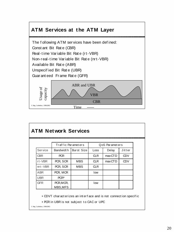
ATM Services at the ATM Layer
The following ATM services have been defined:Constant Bit Rate (CBR)Real-time Variable Bit Rate (rt-VBR)Non-real-time Variable Bit Rate (nrt-VBR)Available Bit Rate (ABR) Unspecified Bit Rate (UBR)Guaranteed Frame Rate (GFR)
Time
Usa
ge o
f ca
paci
ty
CBR
VBR
ABR and UBR
© Jörg Liebeherr, 1998-2003
ATM Network Services
Traffic Parameters QoS Parameters Service Bandwidth Burst Size Loss Delay Jitter
CBR PCR CLR maxCTD CDV
rt-VBR PCR, SCR MBS CLR maxCTD CDV nrt-VBR PCR, SCR MBS CLR
ABR PCR, MCR low UBR PCR* GFR PCR,MCR,
MBS,MFS low
• CDVT characterizes an interface and is not connection specific
• PCR in UBR is not subject to CAC or UPC
21
© Jörg Liebeherr, 1998-2003
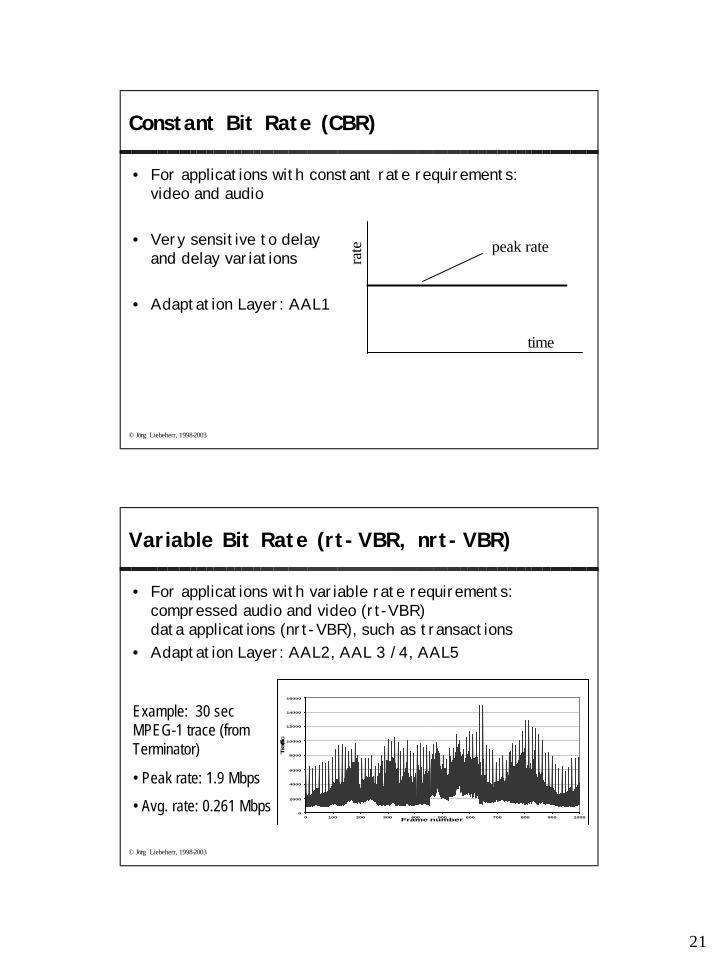
Constant Bit Rate (CBR)
• For applications with constant rate requirements: video and audio
• Very sensitive to delay and delay variations
• Adaptation Layer: AAL1
timera
te peak rate
© Jörg Liebeherr, 1998-2003
Variable Bit Rate (rt-VBR, nrt-VBR)
• For applications with variable rate requirements: compressed audio and video (rt-VBR)data applications (nrt-VBR), such as transactions
• Adaptation Layer: AAL2, AAL 3 /4, AAL5
0
2000
4000
6000
8000
10000
12000
14000
16000
0 100 200 300 400 500 600 700 800 900 1000Frame number
Tra
ffic
Example: 30 sec MPEG-1 trace (from Terminator)
• Peak rate: 1.9 Mbps
• Avg. rate: 0.261 Mbps
22
© Jörg Liebeherr, 1998-2003
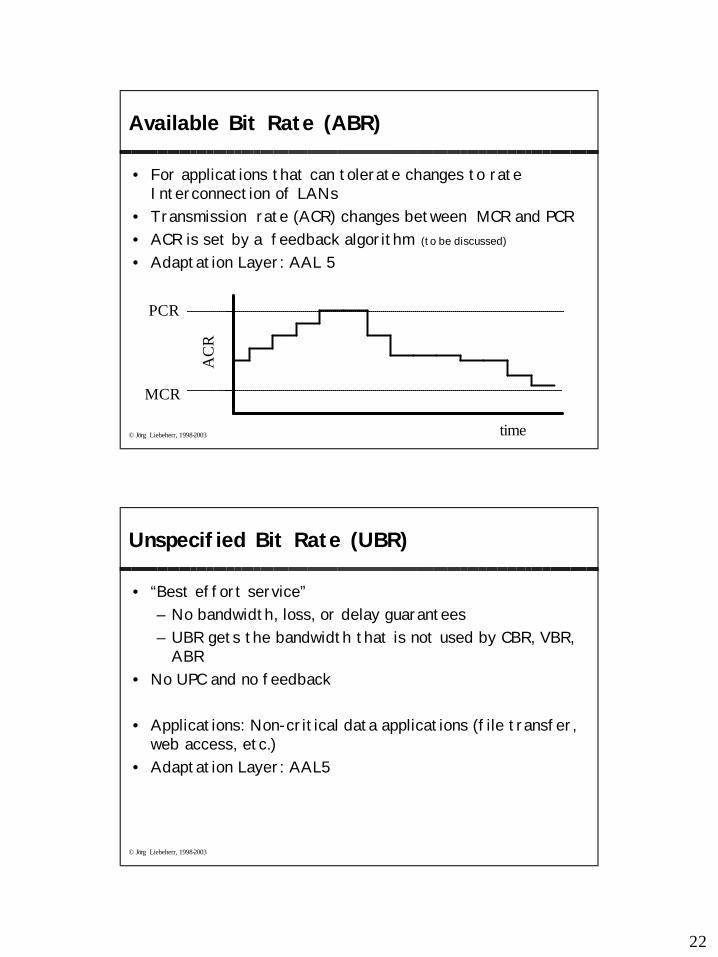
Available Bit Rate (ABR)
• For applications that can tolerate changes to rateInterconnection of LANs
• Transmission rate (ACR) changes between MCR and PCR• ACR is set by a feedback algorithm (to be discussed)
• Adaptation Layer: AAL 5
MCR
PCR
time
AC
R
© Jörg Liebeherr, 1998-2003
Unspecified Bit Rate (UBR)
• “Best effort service” – No bandwidth, loss, or delay guarantees– UBR gets the bandwidth that is not used by CBR, VBR,
ABR• No UPC and no feedback
• Applications: Non-critical data applications (file transfer, web access, etc.)
• Adaptation Layer: AAL5
23
© Jörg Liebeherr, 1998-2003
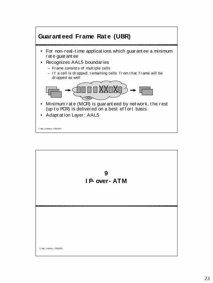
Guaranteed Frame Rate (UBR)
• For non-real-time applications which guarantee a minimum rate guarantee
• Recognizes AAL5 boundaries– Frame consists of multiple cells– If a cell is dropped, remaining cells from that frame will be
dropped as well
• Minimum rate (MCR) is guaranteed by network, the rest (up to PCR) is delivered on a best effort basis.
• Adaptation Layer: AAL5
© Jörg Liebeherr, 1998-2003
9IP-over-ATM
24
© Jörg Liebeherr, 1998-2003
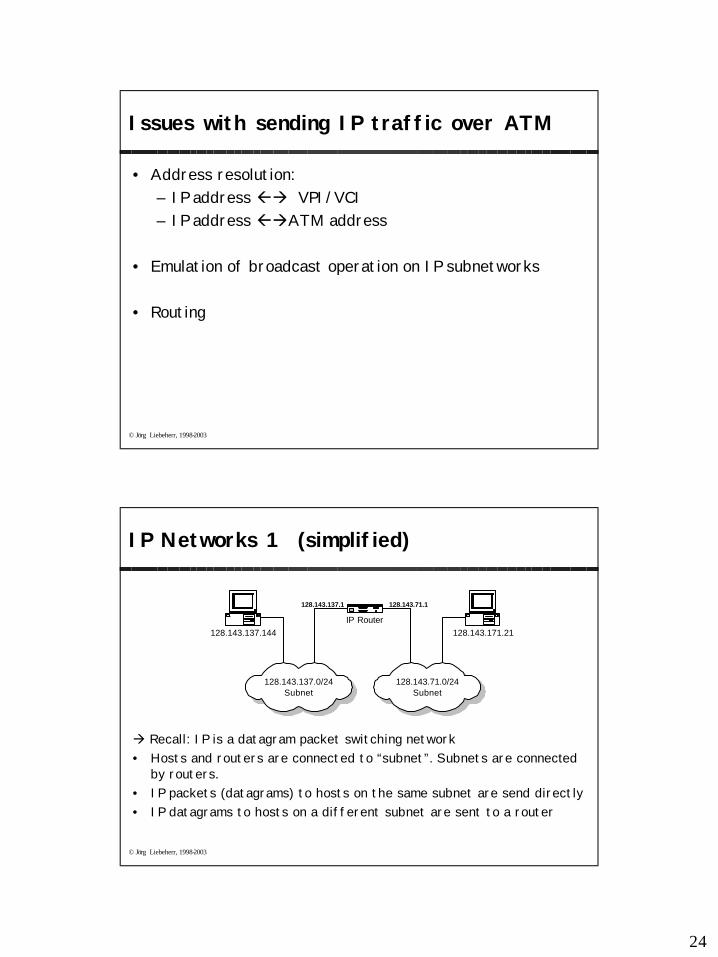
Issues with sending IP traffic over ATM
• Address resolution: – IP address ßà VPI/VCI– IP address ßàATM address
• Emulation of broadcast operation on IP subnetworks
• Routing
© Jörg Liebeherr, 1998-2003
IP Networks 1 (simplified)
à Recall: IP is a datagram packet switching network• Hosts and routers are connected to “subnet”. Subnets are connected
by routers.• IP packets (datagrams) to hosts on the same subnet are send directly• IP datagrams to hosts on a different subnet are sent to a router
IP Router
128.143.137.1 128.143.71.1
128.143.137.144
128.143.137.0/24Subnet
128.143.71.0/24Subnet
128.143.171.21
25
© Jörg Liebeherr, 1998-2003
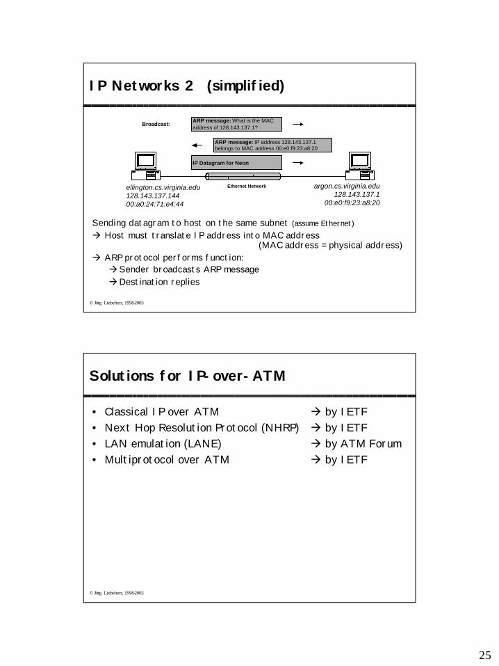
IP Networks 2 (simplified)
Sending datagram to host on the same subnet (assume Ethernet)à Host must translate IP address into MAC address
(MAC address = physical address)à ARP protocol performs function: àSender broadcasts ARP messageàDestination replies
ellington.cs.virginia.edu128.143.137.14400:a0:24:71:e4:44
ARP message: What is the MACaddress of 128.143.137.1?
ARP message: IP address 128.143.137.1belongs to MAC address 00:e0:f9:23:a8:20
IP Datagram for Neon
argon.cs.virginia.edu128.143.137.1
00:e0:f9:23:a8:20
Ethernet Network
Broadcast:
© Jörg Liebeherr, 1998-2003
Solutions for IP-over-ATM
• Classical IP over ATM à by IETF• Next Hop Resolution Protocol (NHRP) à by IETF• LAN emulation (LANE) à by ATM Forum• Multiprotocol over ATM à by IETF
26
© Jörg Liebeherr, 1998-2003
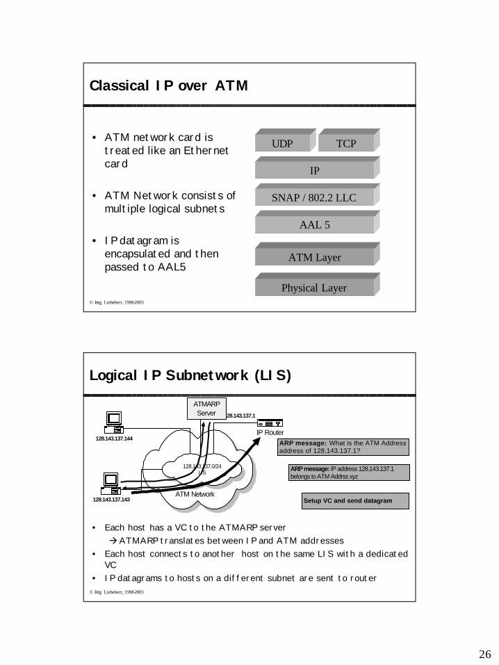
Classical IP over ATM
• ATM network card is treated like an Ethernet card
• ATM Network consists of multiple logical subnets
• IP datagram is encapsulated and then passed to AAL5
AAL 5
ATM Layer
Physical Layer
IP
SNAP / 802.2 LLC
UDP TCP
© Jörg Liebeherr, 1998-2003
Logical IP Subnetwork (LIS)
• Each host has a VC to the ATMARP serveràATMARP translates between IP and ATM addresses
• Each host connects to another host on the same LIS with a dedicated VC
• IP datagrams to hosts on a different subnet are sent to router
ATM Network
IP Router
128.143.137.1
128.143.137.144
128.143.137.143
ATMARPServer
128.143.137.0/24LIS
ARP message: What is the ATM Addressaddress of 128.143.137.1?
ARP message: IP address 128.143.137.1belongs to ATM Addrss xyz
Setup VC and send datagram
27
© Jörg Liebeherr, 1998-2003
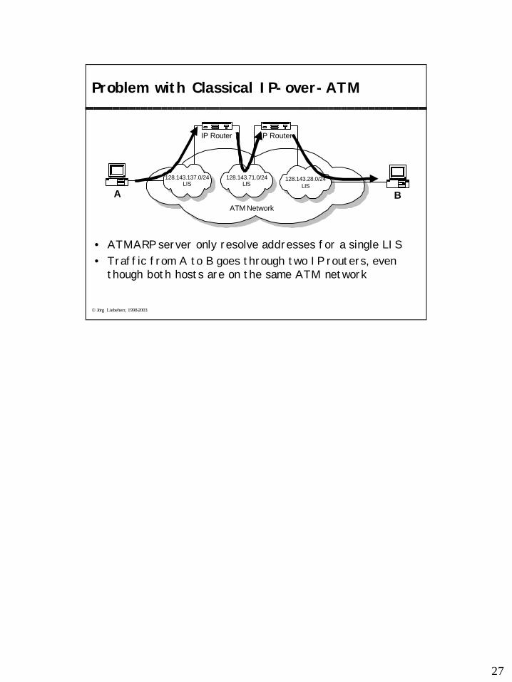
Problem with Classical IP-over-ATM
• ATMARP server only resolve addresses for a single LIS• Traffic from A to B goes through two IP routers, even
though both hosts are on the same ATM network
ATM Network
IP Router
A
128.143.137.0/24LIS
128.143.71.0/24LIS
B
128.143.28.0/24LIS
IP Router