CS323732 Practical 4D Construction Simulation Using Revit ...
17
Page 1 Fall 2019 Ken Flannigan Global Solution Owner, KONE CS323732 Practical 4D Construction Simulation Using Revit and Navisworks Ken Flannigan Global BIM Solution Owner, KONE Josh Willingham BIM Specialist – North America, KONE Description 3D coordination is now used in most projects to help improve predictability during construction. Usually the geometry is only shown in its final constructed location. While it is a big step forward to improving communication and planning, it doesn’t include the space needed during construction—which limits what can be predicted during the construction process. This session will show how to apply a practical approach to 4D construction simulation, including large- equipment routing, clear work areas, on-site material storage, and key milestone indicators. We are using a combination of Revit software and Navisworks software to visualize and animate these important factors in gaining benefit from virtual construction. Speaker(s) Ken Flannigan is a technology leader who works with KONE to guide BIM processes and research globally. Ken believes that there are great industry challenges afoot as benefits of BIM have gone mostly unrealized and industry-wide productivity has remained flat. Ken has led technology implementation efforts including BIM automation of configure, price, quote systems and integrating BIM-centric workflows on an local and global scale. Ken serves on the BIMForum LOD Specification Committee and is a LEED Accredited Professional. Learning Objectives Discover 4D construction simulation Learn about use cases that can benefit from 4D construction-site simulation Discover the role and workflow with Revit and Navisworks for visualizing 4D construction-site simulation Compare explicit 4D simulation to a construction-site digital twin
Transcript of CS323732 Practical 4D Construction Simulation Using Revit ...

Page 1
Fall 2019
Ken Flannigan
Global Solution Owner, KONE
CS323732
Practical 4D Construction Simulation Using Revit and Navisworks Ken Flannigan Global BIM Solution Owner, KONE Josh Willingham BIM Specialist – North America, KONE
Description
3D coordination is now used in most projects to help improve predictability during construction. Usually the geometry is only shown in its final constructed location. While it is a big step forward to improving communication and planning, it doesn’t include the space needed during construction—which limits what can be predicted during the construction process. This session will show how to apply a practical approach to 4D construction simulation, including large-equipment routing, clear work areas, on-site material storage, and key milestone indicators. We are using a combination of Revit software and Navisworks software to visualize and animate these important factors in gaining benefit from virtual construction.
Speaker(s)
Ken Flannigan is a technology leader who works with KONE to guide BIM processes and research globally. Ken believes that there are great industry challenges afoot as benefits of BIM have gone mostly unrealized and industry-wide productivity has remained flat. Ken has led technology implementation efforts including BIM automation of configure, price, quote systems and integrating BIM-centric workflows on an local and global scale. Ken serves on the BIMForum LOD Specification Committee and is a LEED Accredited Professional.
Learning Objectives
Discover 4D construction simulation
Learn about use cases that can benefit from 4D construction-site simulation
Discover the role and workflow with Revit and Navisworks for visualizing 4D construction-site simulation
Compare explicit 4D simulation to a construction-site digital twin

Page 2
Fall 2019
Ken Flannigan
Global Solution Owner, KONE
4D construction simulation
When virtual construction professionals coordinate 3D models they are taking models representing the final installed position of all components from all trades. 3D coordination only tells part of the story. So, what are we missing? If our ultimate effort is to better understand the construction site, and thus improve schedule accuracy and planning predictability, we aren’t usually coordinating the right thing. I’d even say we may be missing more than half of the story.
Separating 4D fact from 4D fiction 90%+ of 4D going on in the industry is for show only, very few examples exist where 4D is implemented in a way that improves communication and onsite efficiency. It is kind of the ultimate “BIM-washing” – still one of my favorite terms. Most commonly this is an animation to demonstrate skill and sophistication in front of a customer during the interview process. Not to disparage selling the value of these technologies as early as possible and to the right people, it just usually never goes further than that. This session is about making the “show” of 4D turn into a highly practical and valuable tool, easily enabled with 3D BIM to solve very specific problems. We’ll also look ahead at where this foundational construction site coordination can take us.
Use cases that can benefit from 4D construction-site simulation
When 3D coordination was initially used to drive construction value from BIM, we didn’t immediately try to coordinate the entire building in 3D. It started with specific tests/use cases. Structure vs. Architecture, MEP Equipment vs. Structure. Not all aspects of a building could be understood in 3D right away. Just like with the evolution of 3D coordination, 4D coordination has to start with specific use cases.
3D coordination shows objects in their final installed position
4D construction simulation shows the objects and space needed
during construction
“Hollywood BIM”
Using BIM for presentation purposes only.
Not using BIM to solve issues and improve building design,
construction and operation

Page 3
Fall 2019
Ken Flannigan
Global Solution Owner, KONE
3 types of 4D
Site logistics model Ok, so technically this is just another type of 3D model, and can be used in a project timeline simulation, but also can provide value by planning clear work areas looking for trade overlap as well as helping onsite material storage coordination. These are topics we always covered with customers, but usually as part of a site preparedness guide buried in the detail of a long document. Raising these site coordination topics in a 3D form greatly improves awareness and communication.
Figure 2 - Site logistics models placed on a tower site. Helps plan project sequencing, the need to plan for multiple deliveries and onsite storage optimization
Figure 1 - Equipment model examples that include site logistics geometry representing clear work area requirements and onsite material storage needs.

Page 4
Fall 2019
Ken Flannigan
Global Solution Owner, KONE
Equipment routing animation This is by far the most valuable and common type of 4D simulation we have offered. It applies to anything that needs to move through a construction site and is only limited by what you can predict about the actual site condition when the installation takes place.
Figure 3 - Still images of an equipment routing animation. This escalator truss was split in 2 to allow installation after superstructure is erected.

Page 5
Fall 2019
Ken Flannigan
Global Solution Owner, KONE
Project timeline simulation This is the most recognizable and common 4D service, it is also the primary way 4D “fiction” is spread. To date, we have seen limited examples of overall project simulation as a planning tool or as something the actual schedule could be measured against. Real value can be driven from this type of visualization if you consider the other types of 4D we have listed above ( site logistics and equipment routing) in addition to adding geometry to visually track tasks or site readiness requirements that cannot be easily communicated in a 3D building model. For this we apply model text that can we call a Key Milestone Indicator. These key milestone indicators can be color coded by the construction planner to clarify responsible parties.
Figure 5 - Traditional timeline simulation where objects are attached to a task and appear transparent while the task is active and then looking complete at the end of the task.
Figure 4 - Equipment model including site logistics geometry and key milestone indicators for objects that could not be easily represented in 3D otherwise.
Page 6
Fall 2019
Ken Flannigan
Global Solution Owner, KONE
Workflow with Revit and Navisworks for visualizing 4D construction-site simulation
Revit Revit is required to perform 4D simulation for the following services
Site logistics model Revit is where we add objects that represent the areas we need on the construction site, outside of the final installed equipment location this includes:
Clear work areas
Onsite material storage areas
Staging or delivery areas
This is stored in a template to be included in a separate 3D model. Steps:
1. Link Equipment models and architectural/structural models 2. Copy important levels and Acquire Coordinates 3. Place the site logistics components on each level, as required 4. Hide Linked models and export 4D Site Logistics model to desired format (DWF)
Figure 6 - Site Logistics shapes for different clear work and onsite material storage specific to product type
Figure 7 - Example of site logistics components placed adjacent to the equipment models

Page 7
Fall 2019
Ken Flannigan
Global Solution Owner, KONE
Equipment routing animation It may be necessary to use Revit to
Add generalized crane rigging when lowering items from above.
Add installation equipment that is required to move with the equipment during routing (e.g. sleds)
Adding geometry to represent accurate overall size of the equipment in the state it will be routed into place.
Steps:
1. Use the Site logistics model as a starting point, if available.
2. Insert onsite construction equipment to be used in routing
3. If adding rigging elements to an item, use an In-Place model to generate a simplified version of the crane rigging, as necessary to more completely represent the size of the routed equipment.
Figure 9 - In place model created for escalator rigging, simplified version of geometry is all that is necessary.
Figure 8 - examples of equipment used for equipment routing: gantries for escalator installation (top), guide rail sleds for elevator installation (bottom)
Page 8
Fall 2019
Ken Flannigan
Global Solution Owner, KONE
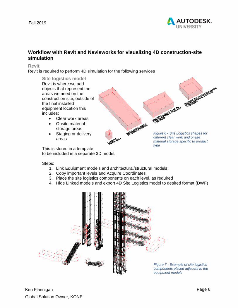
Project timeline simulation To achieve a project timeline simulation it may be necessary to use Revit to:
Break model elements up into parts / pieces for simulation when it was modeled as a single item for 3D coordination purposes.
Add data to model elements that corresponds with project sequence task name
Add installation equipment (e.g. cranes, sleds, carts), also done in equipment routing.
Add Key Milestone indicators to represent milestones that cannot otherwise be represented in the 3D model. (i.e. site readiness requirements)
Revit family editing may necessary to split objects that are not normally modeled in two pieces, at KONE the best example of this is the escalator truss. The only extra geometry you may add using Revit is the key milestone indicators. Steps:
1. Working in a 4D template, use model text based component to add notes to the 4D model Position the model text component outside of the building model in an easily viewed area from the standard isometric views.
Figure 10 - Example of 2 key milestone indicators placed outside of the building geometry

Page 9
Fall 2019
Ken Flannigan
Global Solution Owner, KONE
Navisworks Navisworks is where the all coordination and simulation takes place. It is also important because of the integration with BIM 360 Glue. We have seen many projects use cloud-based coordination/model sharing tools and it saves us a lot of time in downloading and model updating. Regardless, the 4D tasks remain the same: extra models appended to the federated building information model whether that is local or through a central connected repository.
Site logistics Model The site logistics models should be a requirement of any practical 4D simulation to clarify site readiness. It is also foundational for computational space planning for construction, optimizing onsite construction traffic and supply chain. For now, the model is static. Nothing is animated but Navisworks is still the best place to view, comment and coordinate the space needed for clear work areas, onsite material storage, and staging or delivery areas. Usually this helps us point out the need for multiple deliveries as well as the topic of project sequencing.
Steps: 1. Export the site logistics model from Revit to a Navisworks format, This is a
different model than your building geometry. 2. Append the site logistics model exported from Revit, we use DWF or IFC. 3. Isolate building floors with site logistics using sectioning tools. 4. Save Viewpoint(s) 5. If necessary, select the object and use the Item tools to Move, Rotate, or Scale 6. Screen capture or export image formats.
Figure 11 - All site logistics models represented at once.
Page 10
Fall 2019
Ken Flannigan
Global Solution Owner, KONE
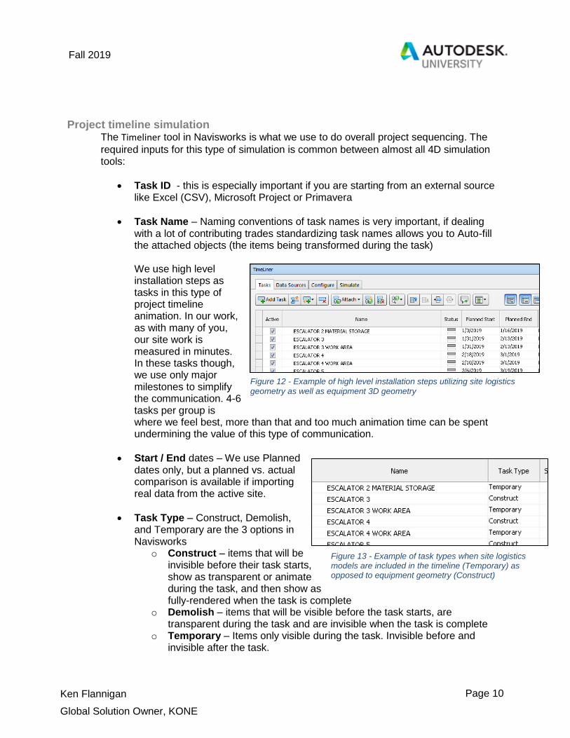
Project timeline simulation The Timeliner tool in Navisworks is what we use to do overall project sequencing. The
required inputs for this type of simulation is common between almost all 4D simulation tools:
Task ID - this is especially important if you are starting from an external source like Excel (CSV), Microsoft Project or Primavera
Task Name – Naming conventions of task names is very important, if dealing with a lot of contributing trades standardizing task names allows you to Auto-fill the attached objects (the items being transformed during the task)
We use high level installation steps as tasks in this type of project timeline animation. In our work, as with many of you, our site work is measured in minutes. In these tasks though, we use only major milestones to simplify the communication. 4-6 tasks per group is where we feel best, more than that and too much animation time can be spent undermining the value of this type of communication.
Start / End dates – We use Planned dates only, but a planned vs. actual comparison is available if importing real data from the active site.
Task Type – Construct, Demolish, and Temporary are the 3 options in Navisworks
o Construct – items that will be invisible before their task starts, show as transparent or animate during the task, and then show as fully-rendered when the task is complete
o Demolish – items that will be visible before the task starts, are transparent during the task and are invisible when the task is complete
o Temporary – Items only visible during the task. Invisible before and invisible after the task.
Figure 12 - Example of high level installation steps utilizing site logistics geometry as well as equipment 3D geometry
Figure 13 - Example of task types when site logistics models are included in the timeline (Temporary) as opposed to equipment geometry (Construct)

Page 11
Fall 2019
Ken Flannigan
Global Solution Owner, KONE
Attachment – this is the model being attached and cannot come from an external source. It is the geometry being acted upon during the task, it can be a set or explicit selection. Attaching items can be the most time consuming aspect of project timeline simulation.
Tip: Create Sets of the items and make sure the syntax of the set matches the task name it is being attached to. This is a very fast way to Auto-attach using a rule where is the task name and the set name matches, it will be attached.
Using search sets and data standards and you could very well go from model to simulation in minutes instead of hours.
Animation - It is possible to include equipment routing animations within your timeline. Animator scenes or individual animation sets can be selected for a task.
Other Timeliner Tabs:
Data Sources – Add tasks through mapping of CSV, Microsoft Project or Primavera schedule sources. Here you can map from the source to the Navisworks Timeliner tasks but there is no bi-directional connection with those sources so changes should be made in your scheduling application and refreshed here, not changed in Navisworks directly unless that will be manually transposed to the schedule application.
Figure 14 - Timeline tasks tab complete with task name, start/end, task type, and attachment.
Figure 15 - Timeliner window, Data sources tab: here you can import a schedule from an external source
Page 12
Fall 2019
Ken Flannigan
Global Solution Owner, KONE
Schedule manipulation is commonly done outside of Navisworks even if the only purpose for that specific project timeline is for 4D project sequencing. This is due to the robust feature sets of project management tools to change a task and it automatically adjust interdependent tasks.
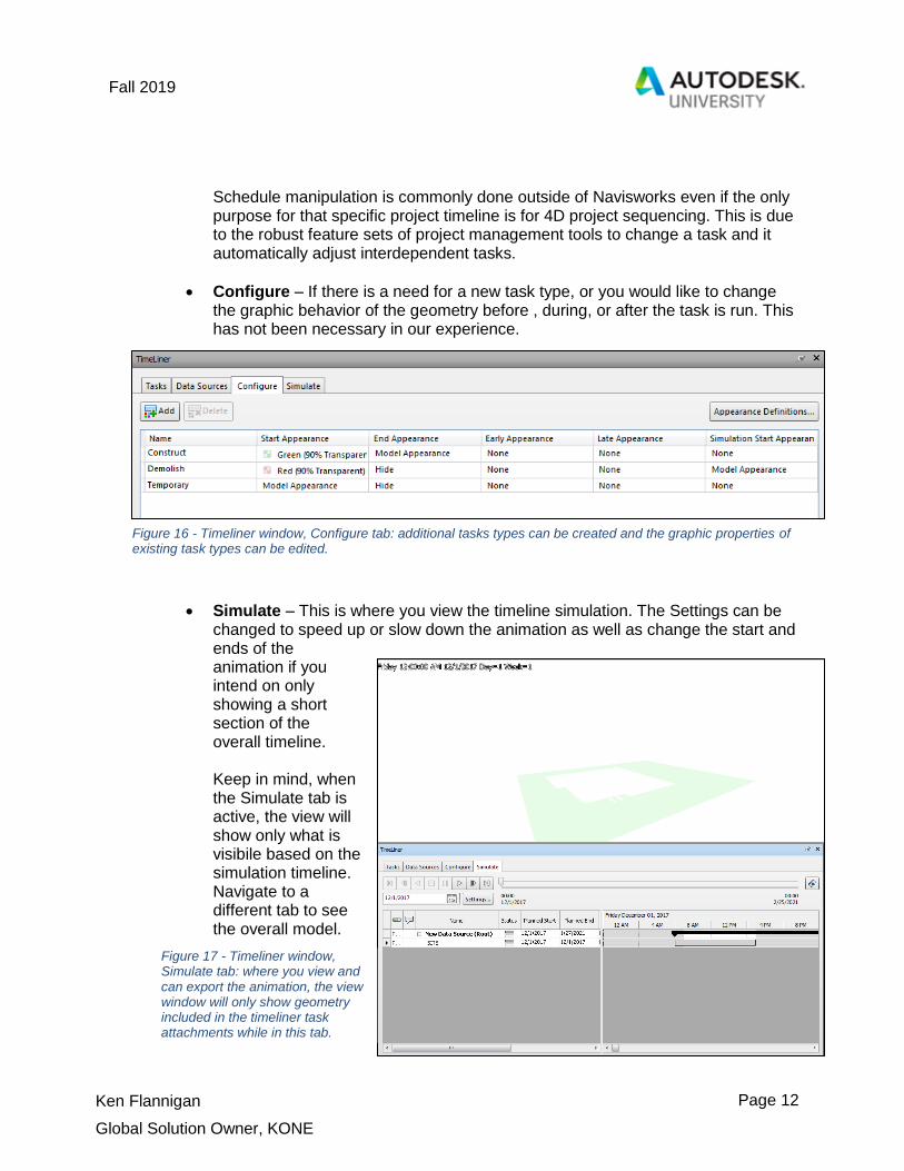
Configure – If there is a need for a new task type, or you would like to change the graphic behavior of the geometry before , during, or after the task is run. This has not been necessary in our experience.
Simulate – This is where you view the timeline simulation. The Settings can be changed to speed up or slow down the animation as well as change the start and ends of the animation if you intend on only showing a short section of the overall timeline. Keep in mind, when the Simulate tab is active, the view will show only what is visibile based on the simulation timeline. Navigate to a different tab to see the overall model.
Figure 16 - Timeliner window, Configure tab: additional tasks types can be created and the graphic properties of existing task types can be edited.
Figure 17 - Timeliner window, Simulate tab: where you view and can export the animation, the view window will only show geometry included in the timeliner task attachments while in this tab.

Page 13
Fall 2019
Ken Flannigan
Global Solution Owner, KONE
Equipment routing The Animator tools in Navisworks is what we use to animate a piece of equipment and accompanying rigging into place. Navisworks is the best place to do this because of the flexibility in the models that can be appended. As with all 4D, we start with the 3D coordination model. We need to save a viewpoint that will have elements hidden that are not yet present on the construction site. Usually just using the structural model is enough when combined with our equipment and site logistics model. The architectural model may be useful or a point cloud if it is available. The Animator uses keyframes and an attached object that has transformations acted upon it, concluded at each keyframe.
Transformations include: transparency, scale, rotation, and movement. Multiple transformations can be applied to a single keyframe, The space between the key frames is an even transformation between 2 end states. Think of it as a ‘straight line’ between keyframes, although it can include rotation. If more steps are required, more keyframes are required.
By starting with the 3D coordination model, we see the model in its final installed location, this should be the condition at the final keyframe of the equipment routing animation. First a Scene needs to be added., then animation set should be set. Multiple animation sets (groups of geometry) can be in a single scene. All items in an animation set transform together. Then we start capturing keyframes. Move the time bar to a rough estimate of how long we’d like the animation to take. Usually our animations are quite short so 40 seconds should suffice. This can always be adjusted later.
Figure 18 - Example of multiple[le Animation scenes representing different areas or options. The Animation sets are organized below the Scene. The animation sets are where the keyframes are captured.

Page 14
Fall 2019
Ken Flannigan
Global Solution Owner, KONE
Figure 21 - Example of a view where the animation scene will play, save viewpoints to clearly show equipment routing options, hiding unnecessary geometry .
From here we capture successive key frames moving the time bar closer to zero seconds between each transformation. The steps are:
1. Move the time bar to the starting keyframe (~40 seconds in)
2. Capture a key frame – this represents the end of the animation
3. Move the time bar earlier (2-5 seconds) so now we are at the time 35 – 38 seconds
4. Choose one or more transform and move the equipment animation set to the condition representing the culmination of movement and/or visibility changes from the previous key frame.
5. Capture a key frame. 6. Repeat steps 3-5 until the position and/or visibility of the equipment animation set
is in its starting position. 7. Play the animation
and re-positon each keyframe to achieve a pleasant speed.
Animations can be played by selecting on the scene name and clicking Play. This animation has been the most valuable 4D service we perform. It allows us to test an installation condition and better explain our constraints to our customer to ultimately achieve the best possible result.
Figure 19 - For each animation set move the time slider to the end of the animation, capture first key frame, move time slider earlier, transform and capture a new keyframe
Figure 20 – Repeat for multiple animation sets in a scene, if necessary. When complete, the animation scene can be played forward. The end condition, or last keyframe, will be the equipment in the final installed location.

Page 15
Fall 2019
Ken Flannigan
Global Solution Owner, KONE
Explicit 4D simulation versus a construction-site digital twin
Most project simulation falls into the category of “Hollywood BIM”. It is interesting, and most people enjoy watching a 90 second animated video of their project but it is for entertainment purposes only. This session’s purpose was to introduce ways that we implement 4D coordination and simulation on real projects in a practical way. We are usually doing this with a very specific purpose, a question is asked and if a simulation can help provide an answer, we simulate. We ask an explicit question and simulate to solve. For instance:
If a customer wants to see a high level animation of equipment being installed, even though it might not be a hardcore preconstruction planning use case, it still is a question that we can help explain through a model and animation.
If a contractor is uncertain that we will be able to lower the escalator truss into place without needing to split the pre-fabricated truss, we can animate that.
If we need to test the size and movement constraints of material transportation systems, we can animate that
If we are dealing with a very tight construction site, onsite material storage needs may be best communicated in a 3D model view, we can model that.
If we always apply 4D coordination in this way we avoid the “purely for entertainment purposes” pitfalls of a lot of 4D being produced.
Our strategy today:
Pose and answer specific questions through construction site
modeling (3D) and animation/simulation (4D)

Page 16
Fall 2019
Ken Flannigan
Global Solution Owner, KONE
What is a construction site digital twin? On the other end of the spectrum is an overall digital representation of a construction site. Although the term “digital twin” has many interpretations, digital twins of the construction site can be leveraged in 2 ways:
Preconstruction simulation and analysis When the construction requirements for all trades can be represented digitally over time, there is an opportunity to plan the construction site computationally. Think of the generative / computational design tools available today applied to the shapes representing work areas, material storage and egress areas during construction. The process could simulated iteratively showing different trades progress through the project highlighting optimized adjacencies and overlap in similar logical engines.
Real-time digital construction site Consider 2 characteristics of digital twin:
The digital representation must exist as a representative of a real object, serving as a container for information about actual live conditions, along with other static properties such as model number, etc.
The digital representation does not just receive information it also is able to act on the real equipment, changing its state that can then be measured or validated through sensor feedback.
The digital twin is not just an accurate 3D representation of something real, it is alive with information and it changes with the real world condition over time. The goal of this type of digital twin for the construction site is to be able to consume large amounts of interconnected information about one or many assets easier. This could be useful to decision makers in order to better assess current conditions and make better future plans. The promise of sensor proliferation, reality capture and ai-object recognition gives us an answer as to what the future may hold for real time digital twins of a construction site.
Preparing for the future:
The construction site can benefit from computational space
planning
A connected building site through reality capture and IoT
sensors can benefit from BIM as a digital container.

Page 17
Fall 2019
Ken Flannigan
Global Solution Owner, KONE
The short step to 5D It could be argued that a 4D construction simulation cannot be complete without financially representing the work completed. In fact, the entire 4D simulation could be based on billing / payouts, or what is widely considered to be 5D construction cost integration. In other words, by attaching models to specific payouts that happen over time (i.e. materials arrive onsite, machine room ready) or interdependent milestones to payouts (i.e. site readiness) then we are accomplishing a version of 5D, as a workflow of 4D. This would be most helpful for the owner, so that an easy comparison can be made with expected site conditions at specific payouts. It is important to identify 5D, not as a single solution, but as an explicit solution for the primary building stakeholders:
Designers 5D – quantity based counts for GMP study or validation
Builders 5D – simulating payouts over time through a 4D simulation during planning that can be compared to real conditions during construction.
Owners 5D – lifecycle cost included as data in the model including regular maintenance costs, expected lifespan, and full replacement cost.
Summary
If you coordinate in 3D today, consider adding key site logistics modeling and large equipment routing to the scope of BIM work on your project in order to improve construction site efficiency. This is incredibly important to the future advancement of BIM use, the smart construction site and the needed step change improvement to construction productivity. Consider construction site modeling and 4D simulation as foundational to enabling prefabrication and the future robotic methods of delivery and construction.
Preparing for the future:
When you accurately simulate and use as a planning tool during
construction, 5D construction cost integration and supply
management is near.