CS152 / Kubiatowicz Lec26.1 5/03/01©UCB Spring 2001 CS152 Computer Architecture and Engineering...
56
5/03/01 ©UCB Spring 2001 CS152 / Kubiatowicz Lec26.1 CS152 Computer Architecture and Engineering Lecture 26 Low Power Design May 3, 2001 John Kubiatowicz (http.cs.berkeley.edu/~kubitron) lecture slides: http://www- inst.eecs.berkeley.edu/~cs152/
-
date post
19-Dec-2015 -
Category
Documents
-
view
220 -
download
0
Transcript of CS152 / Kubiatowicz Lec26.1 5/03/01©UCB Spring 2001 CS152 Computer Architecture and Engineering...
5/03/01 ©UCB Spring 2001 CS152 / Kubiatowicz
Lec26.1
CS152Computer Architecture and Engineering
Lecture 26
Low Power Design
May 3, 2001
John Kubiatowicz (http.cs.berkeley.edu/~kubitron)
lecture slides: http://www-inst.eecs.berkeley.edu/~cs152/
5/03/01 ©UCB Spring 2001 CS152 / Kubiatowicz
Lec26.2
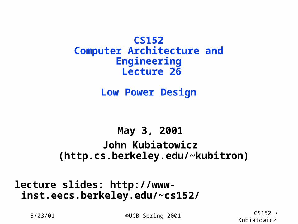
Recap: I/O Summary° I/O performance limited by weakest link in chain between OS and device
° Queueing theory is important
• 100% utilization means very large latency
• Remember, for M/M/1 queue (exponential source of requests/service)
- queue size goes as u/(1-u)
- latency goes as Tser×u/(1-u)
• For M/G/1 queue (more general server, exponential sources)
- latency goes as m1(z) x u/(1-u) = Tser x {1/2 x (1+C)} x u/(1-u)
° Three Components of Disk Access Time:
• Seek Time: advertised to be 8 to 12 ms. May be lower in real life.
• Rotational Latency: 4.1 ms at 7200 RPM and 8.3 ms at 3600 RPM
• Transfer Time: 2 to 12 MB per second
° I/O device notifying the operating system:
• Polling: it can waste a lot of processor time
• I/O interrupt: similar to exception except it is asynchronous
° Delegating I/O responsibility from the CPU: DMA, or even IOP
5/03/01 ©UCB Spring 2001 CS152 / Kubiatowicz
Lec26.3
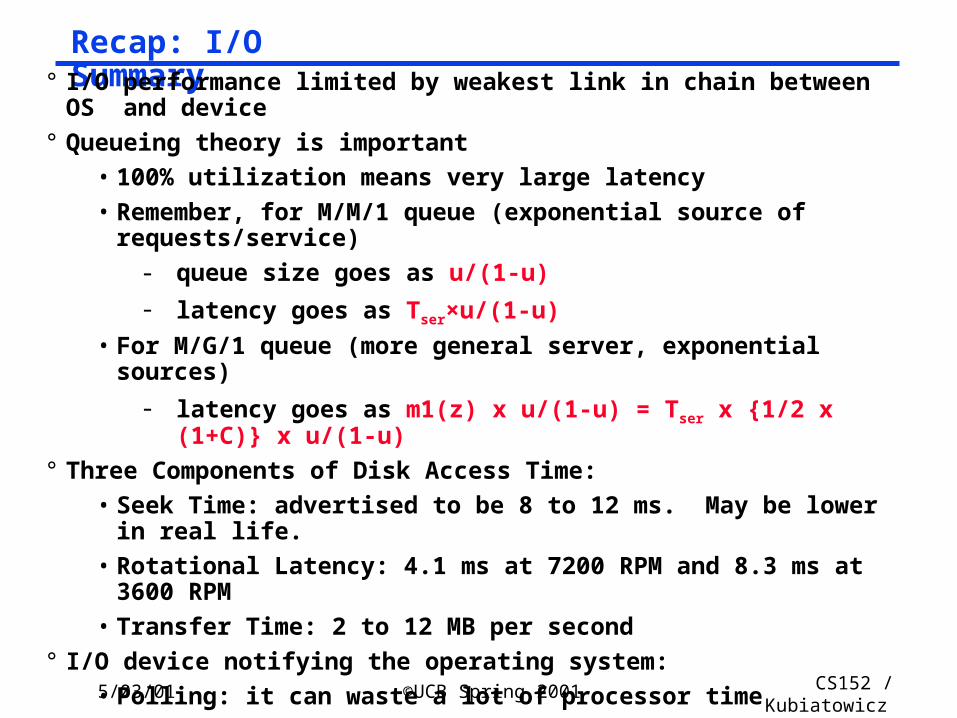
Disk Latency = Queueing Time + Controller time + Seek Time + Rotation Time + Xfer Time
Order of magnitude times for 4K byte transfers:
Average Seek: 8 ms or less
Rotate: 4.2 ms @ 7200 rpm
Xfer: 1 ms @ 7200 rpm
Recap: Disk Device Terminology
5/03/01 ©UCB Spring 2001 CS152 / Kubiatowicz
Lec26.4
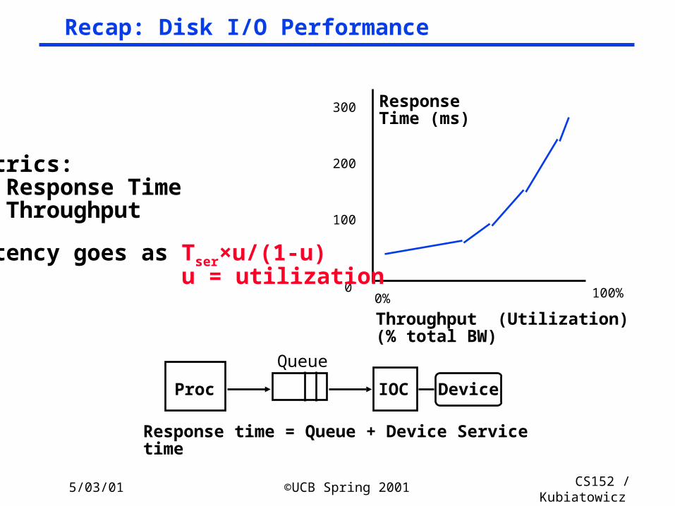
Recap: Disk I/O Performance
Response time = Queue + Device Service time
100%
ResponseTime (ms)
Throughput (Utilization)(% total BW)
0
100
200
300
0%
Proc
Queue
IOC Device
Metrics: Response Time Throughput
latency goes as Tser×u/(1-u) u = utilization
5/03/01 ©UCB Spring 2001 CS152 / Kubiatowicz
Lec26.5
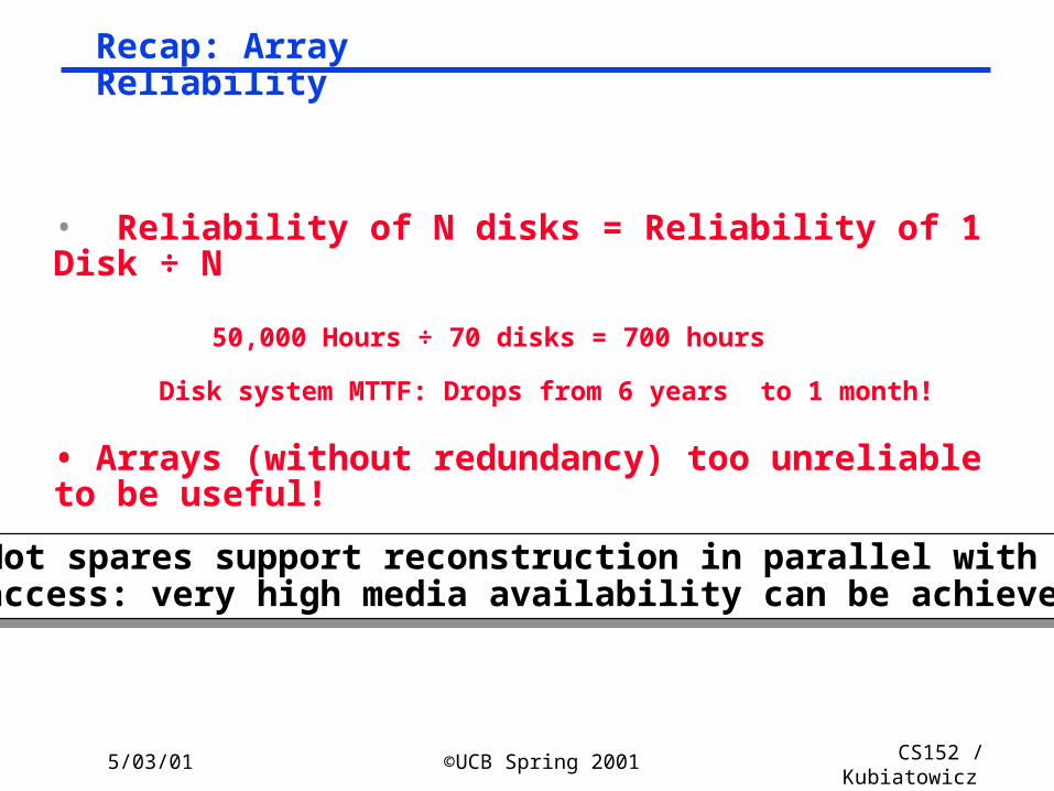
• Reliability of N disks = Reliability of 1 Disk ÷ N
50,000 Hours ÷ 70 disks = 700 hours
Disk system MTTF: Drops from 6 years to 1 month!
• Arrays (without redundancy) too unreliable to be useful!
Hot spares support reconstruction in parallel with access: very high media availability can be achievedHot spares support reconstruction in parallel with access: very high media availability can be achieved
Recap: Array Reliability
5/03/01 ©UCB Spring 2001 CS152 / Kubiatowicz
Lec26.6
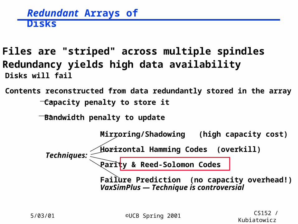
• Files are "striped" across multiple spindles• Redundancy yields high data availability
Disks will fail
Contents reconstructed from data redundantly stored in the array
Capacity penalty to store it
Bandwidth penalty to update
Mirroring/Shadowing (high capacity cost)
Horizontal Hamming Codes (overkill)
Parity & Reed-Solomon Codes
Failure Prediction (no capacity overhead!)VaxSimPlus — Technique is controversial
Techniques:
Redundant Arrays of Disks
5/03/01 ©UCB Spring 2001 CS152 / Kubiatowicz
Lec26.7
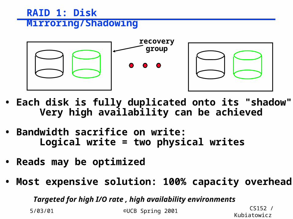
• Each disk is fully duplicated onto its "shadow" Very high availability can be achieved
• Bandwidth sacrifice on write: Logical write = two physical writes
• Reads may be optimized
• Most expensive solution: 100% capacity overhead
Targeted for high I/O rate , high availability environments
recoverygroup
RAID 1: Disk Mirroring/Shadowing
5/03/01 ©UCB Spring 2001 CS152 / Kubiatowicz
Lec26.8
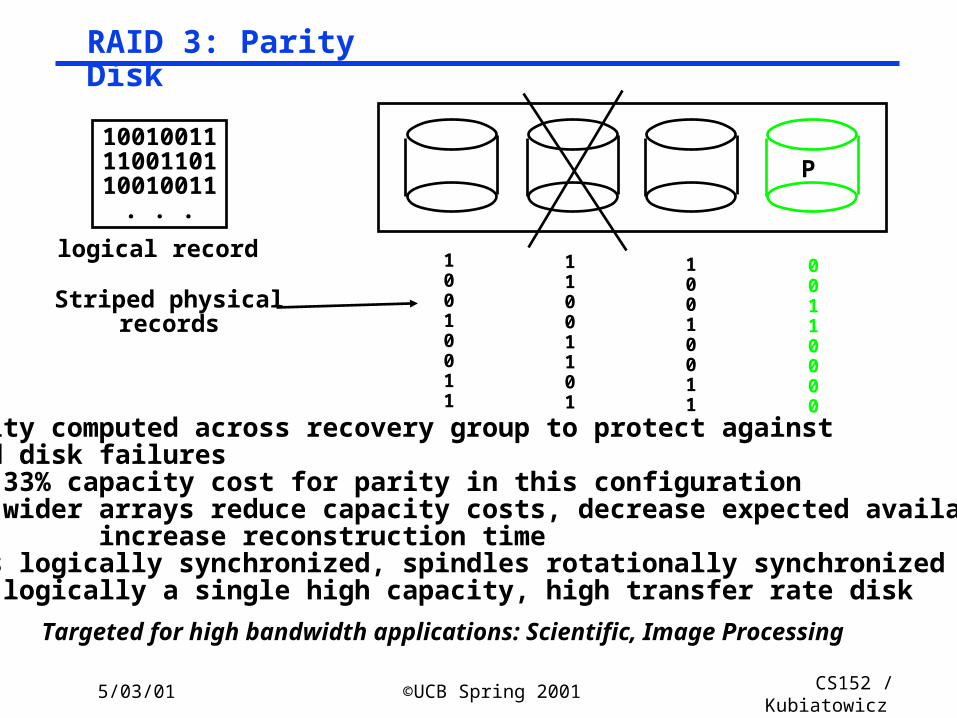
P100100111100110110010011
. . .
logical record 10010011
11001101
10010011
00110000
Striped physicalrecords
• Parity computed across recovery group to protect against hard disk failures 33% capacity cost for parity in this configuration wider arrays reduce capacity costs, decrease expected availability, increase reconstruction time• Arms logically synchronized, spindles rotationally synchronized logically a single high capacity, high transfer rate disk
Targeted for high bandwidth applications: Scientific, Image Processing
RAID 3: Parity Disk
5/03/01 ©UCB Spring 2001 CS152 / Kubiatowicz
Lec26.9
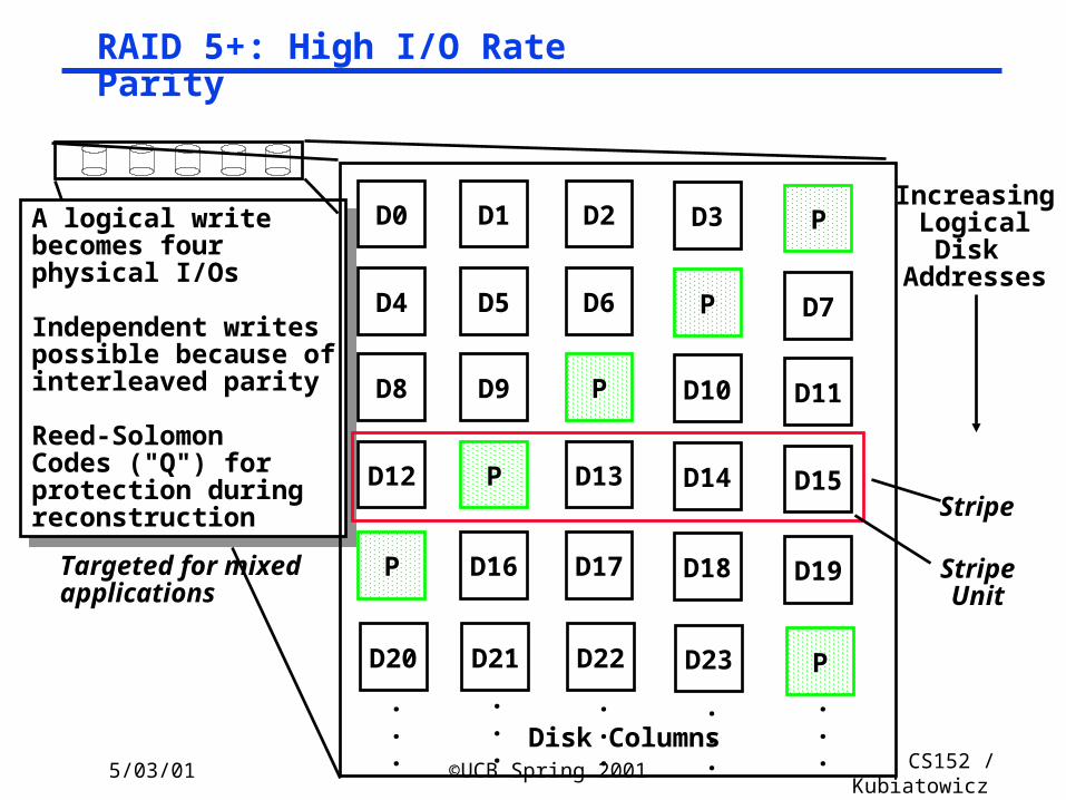
A logical writebecomes fourphysical I/Os
Independent writespossible because ofinterleaved parity
Reed-SolomonCodes ("Q") forprotection duringreconstruction
A logical writebecomes fourphysical I/Os
Independent writespossible because ofinterleaved parity
Reed-SolomonCodes ("Q") forprotection duringreconstruction
D0 D1 D2 D3 P
D4 D5 D6 P D7
D8 D9 P D10 D11
D12 P D13 D14 D15
P D16 D17 D18 D19
D20 D21 D22 D23 P
.
.
.
.
.
.
.
.
.
.
.
.
.
.
.Disk Columns
IncreasingLogical
Disk Addresses
Stripe
StripeUnit
Targeted for mixedapplications
RAID 5+: High I/O Rate Parity
5/03/01 ©UCB Spring 2001 CS152 / Kubiatowicz
Lec26.10
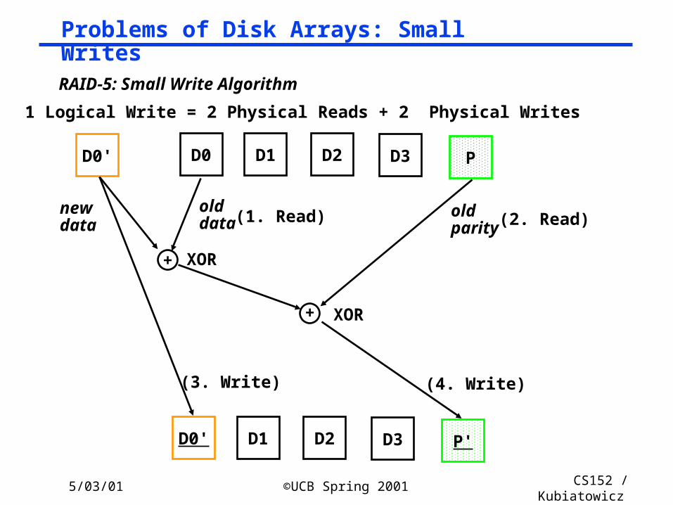
D0 D1 D2 D3 PD0'
+
+
D0' D1 D2 D3 P'
newdata
olddata
old parity
XOR
XOR
(1. Read) (2. Read)
(3. Write) (4. Write)
RAID-5: Small Write Algorithm
1 Logical Write = 2 Physical Reads + 2 Physical Writes
Problems of Disk Arrays: Small Writes
5/03/01 ©UCB Spring 2001 CS152 / Kubiatowicz
Lec26.11
Hewlett-Packard (HP) AutoRAID
° HP has interesting solution which combines both mirroring and RAID level 5.
• Dynamically adapts disk storage
- For recent or highly used data, uses mirroring
- For less recently used data, uses RAID 5
• Gets speed of mirroring when it matters and density of RAID 5 on average
5/03/01 ©UCB Spring 2001 CS152 / Kubiatowicz
Lec26.12
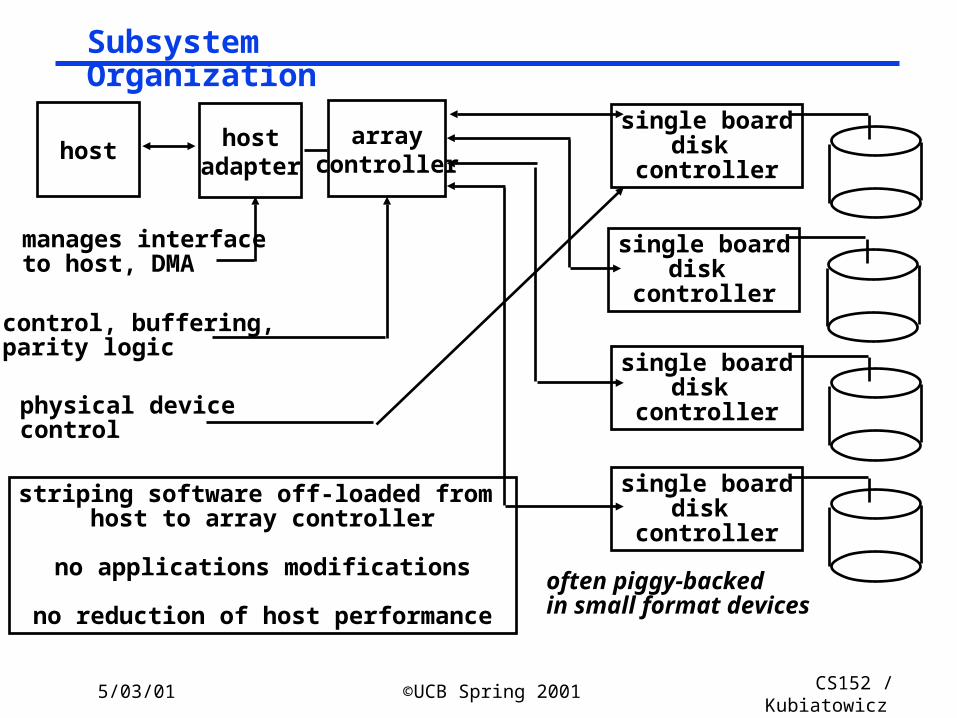
hostarray
controller
single boarddisk
controller
single boarddisk
controller
single boarddisk
controller
single boarddisk
controller
hostadapter
manages interfaceto host, DMA
control, buffering,parity logic
physical devicecontrol
often piggy-backedin small format devices
striping software off-loaded from host to array controller
no applications modifications
no reduction of host performance
Subsystem Organization
5/03/01 ©UCB Spring 2001 CS152 / Kubiatowicz
Lec26.13
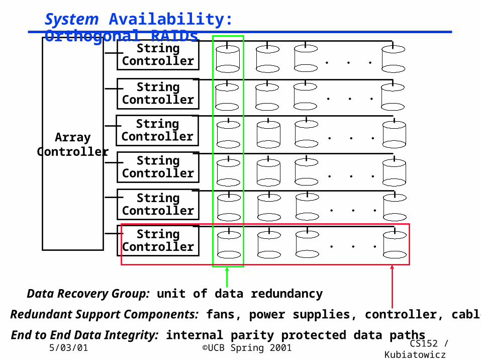
ArrayController
StringController
StringController
StringController
StringController
StringController
StringController
. . .
. . .
. . .
. . .
. . .
. . .
Data Recovery Group: unit of data redundancy
Redundant Support Components: fans, power supplies, controller, cables
End to End Data Integrity: internal parity protected data paths
System Availability: Orthogonal RAIDs
5/03/01 ©UCB Spring 2001 CS152 / Kubiatowicz
Lec26.14
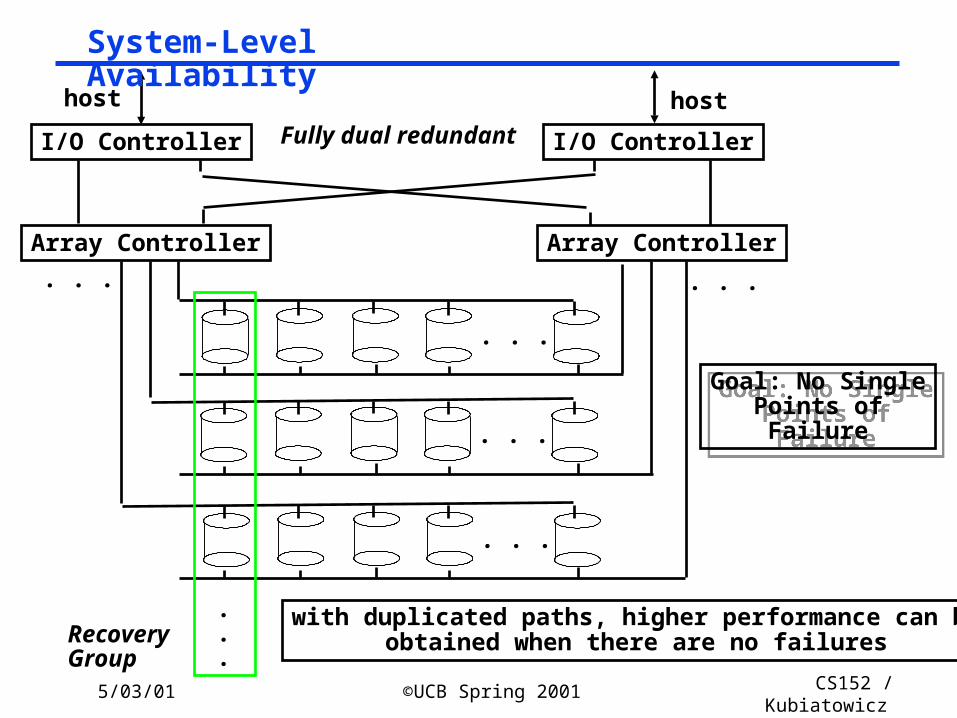
Fully dual redundantI/O Controller I/O Controller
Array Controller Array Controller
. . .
. . .
. . .
. . . . . .
.
.
.RecoveryGroup
Goal: No SinglePoints ofFailure
Goal: No SinglePoints ofFailure
host host
with duplicated paths, higher performance can beobtained when there are no failures
System-Level Availability

5/03/01 ©UCB Spring 2001 CS152 / Kubiatowicz
Lec26.15
Administrivia
° Pending schedule:• Tuesday 5/8: Last class (wrap up, evaluations, etc)• Thursday 5/10: Oral reports: Times TBA
- Signup sheet will be on my office door next week- Project reports must be submitted via web by 5pm on 5/10
• Friday 5/11: Grades ready ° System for examining grades is up
• James posted description of how to use on the web page• Please check your grades!
- Midterm II should be up there by tomorrow° Solutions to Midterm II not up yet (sorry!)
° Oral Report• Powerpoint• 15 minute presentation, 5 minutes for questions
5/03/01 ©UCB Spring 2001 CS152 / Kubiatowicz
Lec26.16
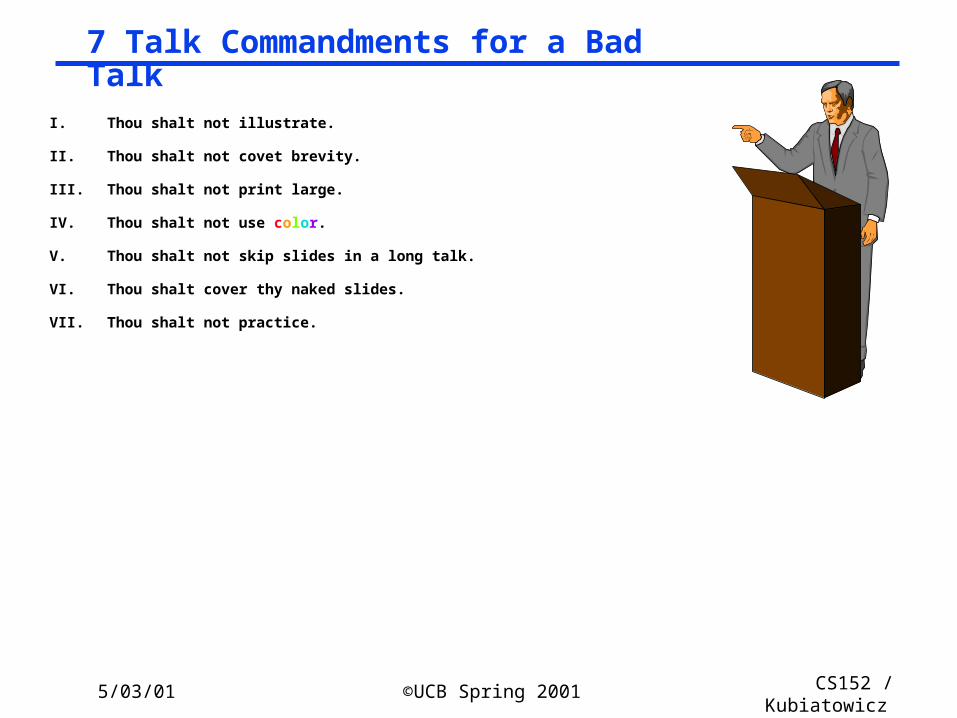
I. Thou shalt not illustrate.
II. Thou shalt not covet brevity.
III. Thou shalt not print large.
IV. Thou shalt not use color.
V.Thou shalt not skip slides in a long talk.
VI. Thou shalt cover thy naked slides.
VII. Thou shalt not practice.
7 Talk Commandments for a Bad Talk
5/03/01 ©UCB Spring 2001 CS152 / Kubiatowicz
Lec26.17
° We describe the philosophy and design of the control flow machine, and present the results of detailed simulations of the performance of a single processing element. Each factor is compared with the measured performance of an advanced von Neumann computer running equivalent code. It is shown that the control flow processor compares favorablylism in the program.
° We present a denotational semantics for a logic program to construct a control flow for the logic program. The control flow is defined as an algebraic manipulator of idempotent substitutions and it virtually reflects the resolution deductions. We also present a bottom-up compilation of medium grain clusters from a fine grain control flow graph. We compare the basic block and the dependence sets algorithms that partition control flow graphs into clusters.
° Our compiling strategy is to exploit coarse-grain parallelism at function application level: and the function application level parallelism is implemented by fork-join mechanism. The compiler translates source programs into control flow graphs based on analyzing flow of control, and then serializes instructions within graphs according to flow arcs such that function applications, which have no control dependency, are executed in parallel.
° A hierarchical macro-control-flow computation allows them to exploit the coarse grain parallelism inside a macrotask, such as a subroutine or a loop, hierarchically. We use a hierarchical definition of macrotasks, a parallelism extraction scheme among macrotasks defined inside an upper layer macrotask, and a scheduling scheme which assigns hierarchical macrotasks on hierarchical clusters.
° We apply a parallel simulation scheme to a real problem: the simulation of a control flow architecture, and we compare the performance of this simulator with that of a sequential one. Moreover, we investigate the effect of modelling the application on the performance of the simulator. Our study indicates that parallel simulation can reduce the execution time significantly if appropriate modelling is used.
° We have demonstrated that to achieve the best execution time for a control flow program, the number of nodes within the system and the type of mapping scheme used are particularly important. In addition, we observe that a large number of subsystem nodes allows more actors to be fired concurrently, but the communication overhead in passing control tokens to their destination nodes causes the overall execution time to increase substantially.
° The relationship between the mapping scheme employed and locality effect in a program are discussed. The mapping scheme employed has to exhibit a strong locality effect in order to allow efficient execution. We assess the average number of instructions in a cluster and the reduction in matching operations compared with fine grain control flow execution.
° Medium grain execution can benefit from a higher output bandwidth of a processor and finally, a simple superscalar processor with an issue rate of ten is sufficient to exploit the internal parallelism of a cluster. Although the technique does not exhaustively detect all possible errors, it detects nontrivial errors with a worst-case complexity quadratic to the system size. It can be automated and applied to systems with arbitrary loops and nondeterminism.
Following all the commandments
5/03/01 ©UCB Spring 2001 CS152 / Kubiatowicz
Lec26.18
° Practice, Practice, Practice!• Use casette tape recorder to listen, practice• Try videotaping• Seek feedback from friends
° Use phrases, not sentences• Notes separate from slides (don’t read slide)
° Pick appropriate font, size (~ 24 point to 32 point)° Estimate talk length
• 2 minutes per slide• Use extras as backup slides (Question and Answer)
° Use color tastefully (graphs, emphasis)° Don’t cover slides
• Use overlays or builds in powerpoint
° Go to room early to find out what is WRONG with setup• Beware: PC projection + dark rooms after meal!
Alternatives to a Bad Talk
5/03/01 ©UCB Spring 2001 CS152 / Kubiatowicz
Lec26.19
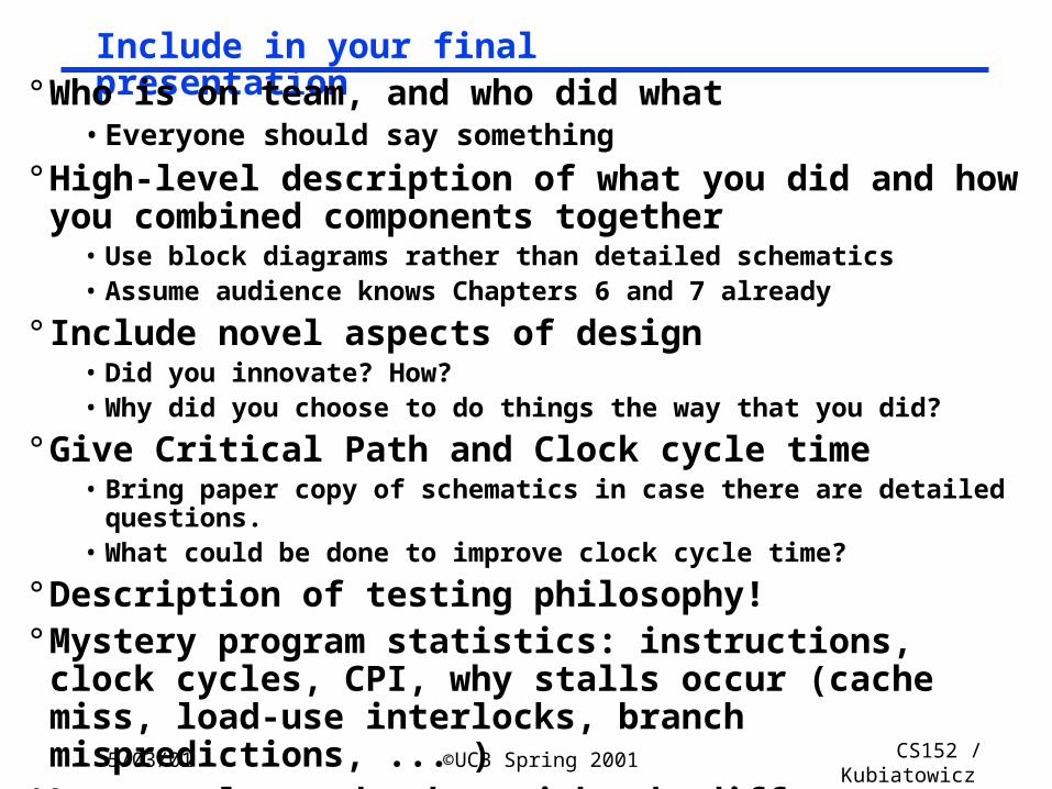
Include in your final presentation° Who is on team, and who did what
• Everyone should say something
° High-level description of what you did and how you combined components together
• Use block diagrams rather than detailed schematics• Assume audience knows Chapters 6 and 7 already
° Include novel aspects of design• Did you innovate? How?• Why did you choose to do things the way that you did?
° Give Critical Path and Clock cycle time• Bring paper copy of schematics in case there are detailed questions.• What could be done to improve clock cycle time?
° Description of testing philosophy!° Mystery program statistics: instructions, clock cycles, CPI,
why stalls occur (cache miss, load-use interlocks, branch mispredictions, ... )
° Lessons learned, what might do different next time
5/03/01 ©UCB Spring 2001 CS152 / Kubiatowicz
Lec26.20
Slides Borrowed from Bob Broderson
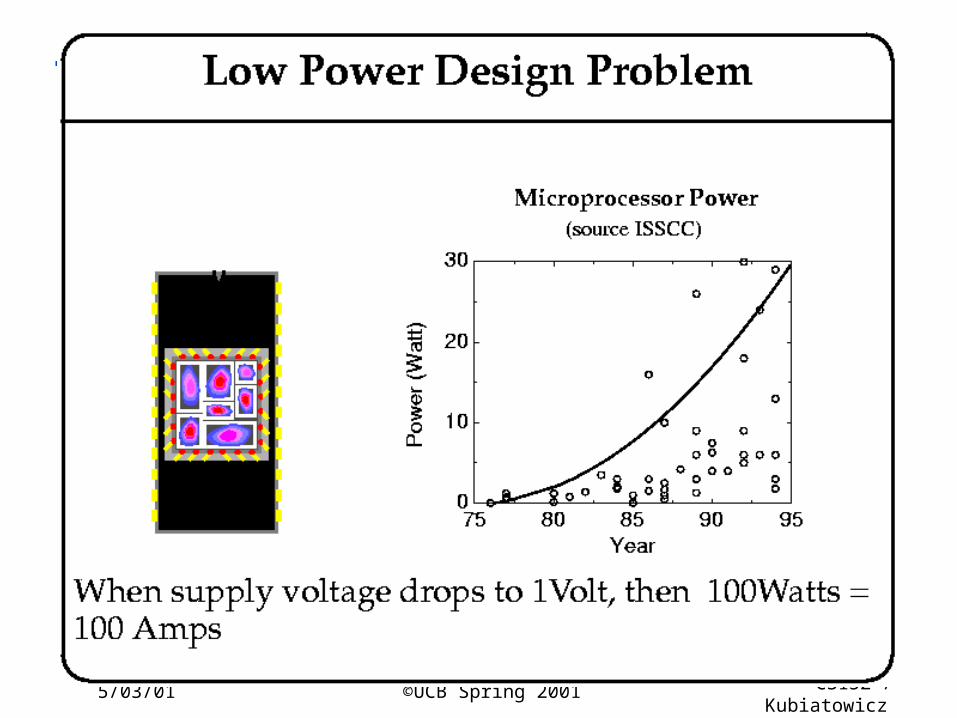
Low Power Design
5/03/01 ©UCB Spring 2001 CS152 / Kubiatowicz
Lec26.21
5/03/01 ©UCB Spring 2001 CS152 / Kubiatowicz
Lec26.22
5/03/01 ©UCB Spring 2001 CS152 / Kubiatowicz
Lec26.23
5/03/01 ©UCB Spring 2001 CS152 / Kubiatowicz
Lec26.24
5/03/01 ©UCB Spring 2001 CS152 / Kubiatowicz
Lec26.25
5/03/01 ©UCB Spring 2001 CS152 / Kubiatowicz
Lec26.26
5/03/01 ©UCB Spring 2001 CS152 / Kubiatowicz
Lec26.27
5/03/01 ©UCB Spring 2001 CS152 / Kubiatowicz
Lec26.28
5/03/01 ©UCB Spring 2001 CS152 / Kubiatowicz
Lec26.29
5/03/01 ©UCB Spring 2001 CS152 / Kubiatowicz
Lec26.30
5/03/01 ©UCB Spring 2001 CS152 / Kubiatowicz
Lec26.31
5/03/01 ©UCB Spring 2001 CS152 / Kubiatowicz
Lec26.32
5/03/01 ©UCB Spring 2001 CS152 / Kubiatowicz
Lec26.33
5/03/01 ©UCB Spring 2001 CS152 / Kubiatowicz
Lec26.34
5/03/01 ©UCB Spring 2001 CS152 / Kubiatowicz
Lec26.35
5/03/01 ©UCB Spring 2001 CS152 / Kubiatowicz
Lec26.36
5/03/01 ©UCB Spring 2001 CS152 / Kubiatowicz
Lec26.37
5/03/01 ©UCB Spring 2001 CS152 / Kubiatowicz
Lec26.38
5/03/01 ©UCB Spring 2001 CS152 / Kubiatowicz
Lec26.39
5/03/01 ©UCB Spring 2001 CS152 / Kubiatowicz
Lec26.40
5/03/01 ©UCB Spring 2001 CS152 / Kubiatowicz
Lec26.41
5/03/01 ©UCB Spring 2001 CS152 / Kubiatowicz
Lec26.42
5/03/01 ©UCB Spring 2001 CS152 / Kubiatowicz
Lec26.43
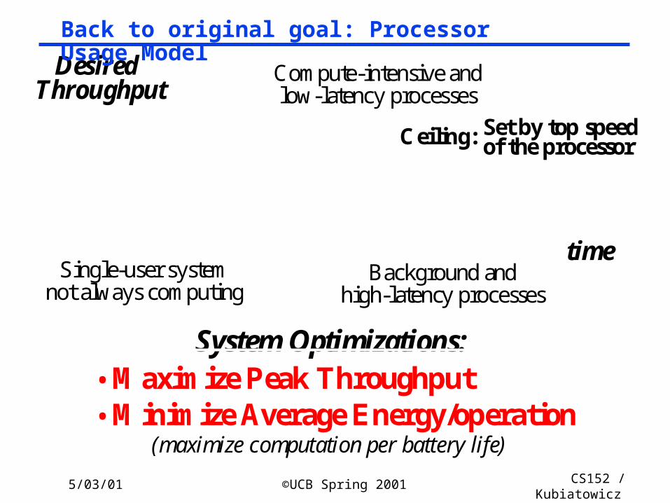
time
DesiredThroughput
Single-user system
Ceiling:
Background and
Compute-intensive and
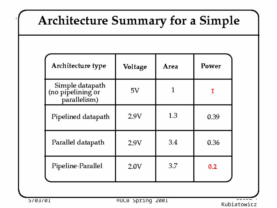
System Optimizations:• Maximize Peak Throughput• Minimize Average Energy/operation
of the processor Set by top speed
high-latency processes
low-latency processes
(maximize computation per battery life)
not always computing
Back to original goal: Processor Usage Model
5/03/01 ©UCB Spring 2001 CS152 / Kubiatowicz
Lec26.44
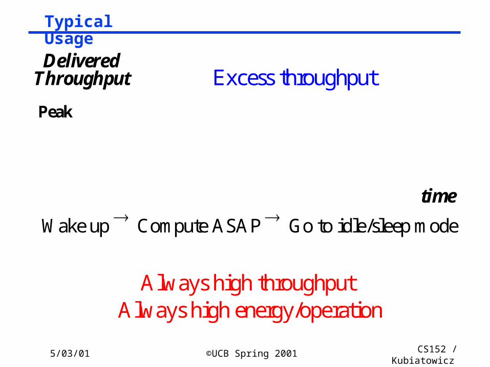
Typical Usage
DeliveredThroughput
Always high throughput
Peak
Wake up Compute ASAP Go to idle/sleep mode
Always high energy/operation
Excess throughput
time
5/03/01 ©UCB Spring 2001 CS152 / Kubiatowicz
Lec26.45
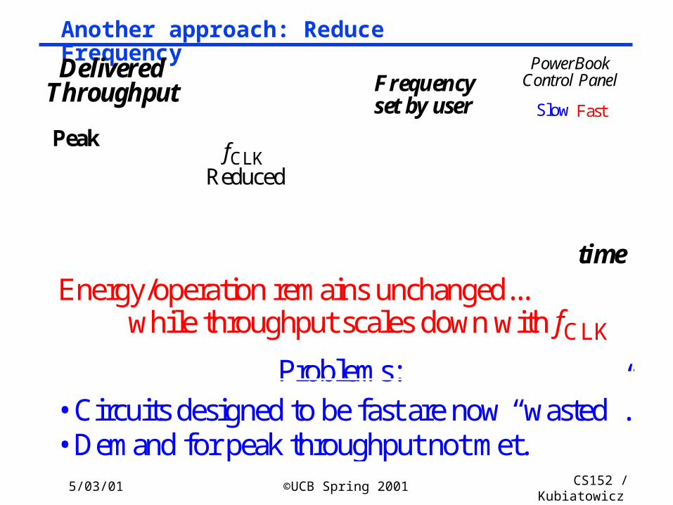
Another approach: Reduce Frequency
fCLKReduced
DeliveredThroughput
Peak
timeEnergy/operation remains unchanged...
while throughput scales down with fCLK
Problems: • Circuits designed to be fast are now “wasted”.• Demand for peak throughput not met.
Slow Fast
PowerBookControl PanelFrequency
set by user
5/03/01 ©UCB Spring 2001 CS152 / Kubiatowicz
Lec26.46
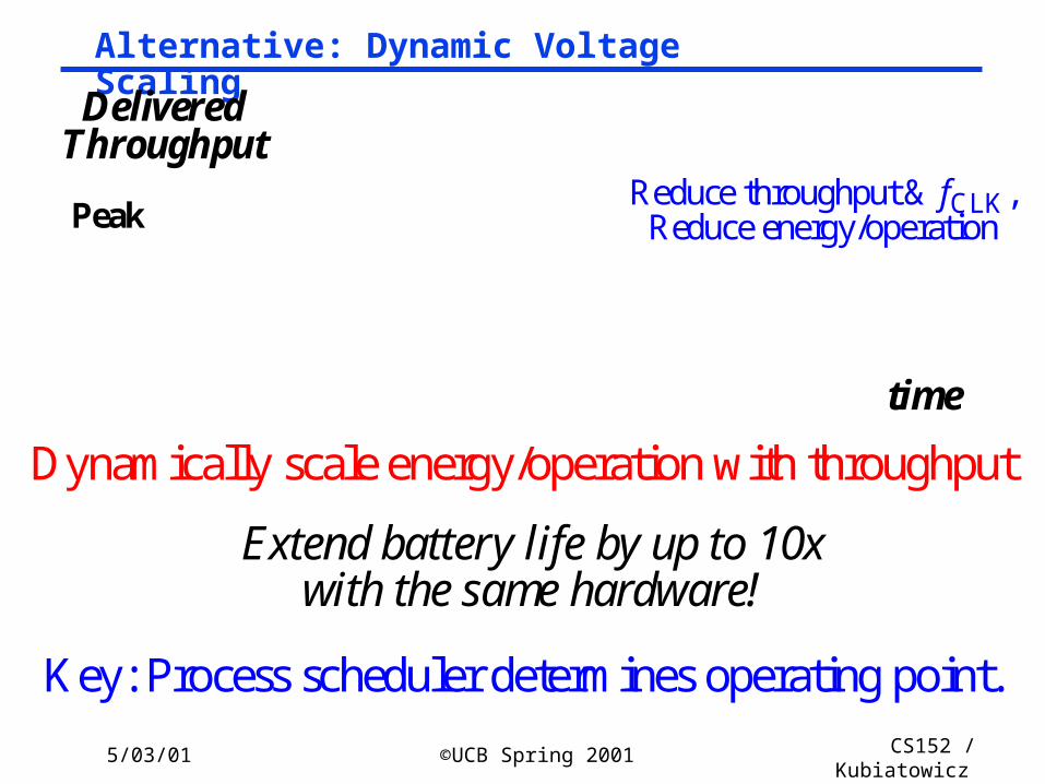
Alternative: Dynamic Voltage Scaling
Dynamically scale energy/operation with throughput
Extend battery life by up to 10xwith the same hardware!
DeliveredThroughput
PeakReduce throughput & fCLK,
Reduce energy/operation
Key: Process scheduler determines operating point.
time
5/03/01 ©UCB Spring 2001 CS152 / Kubiatowicz
Lec26.47
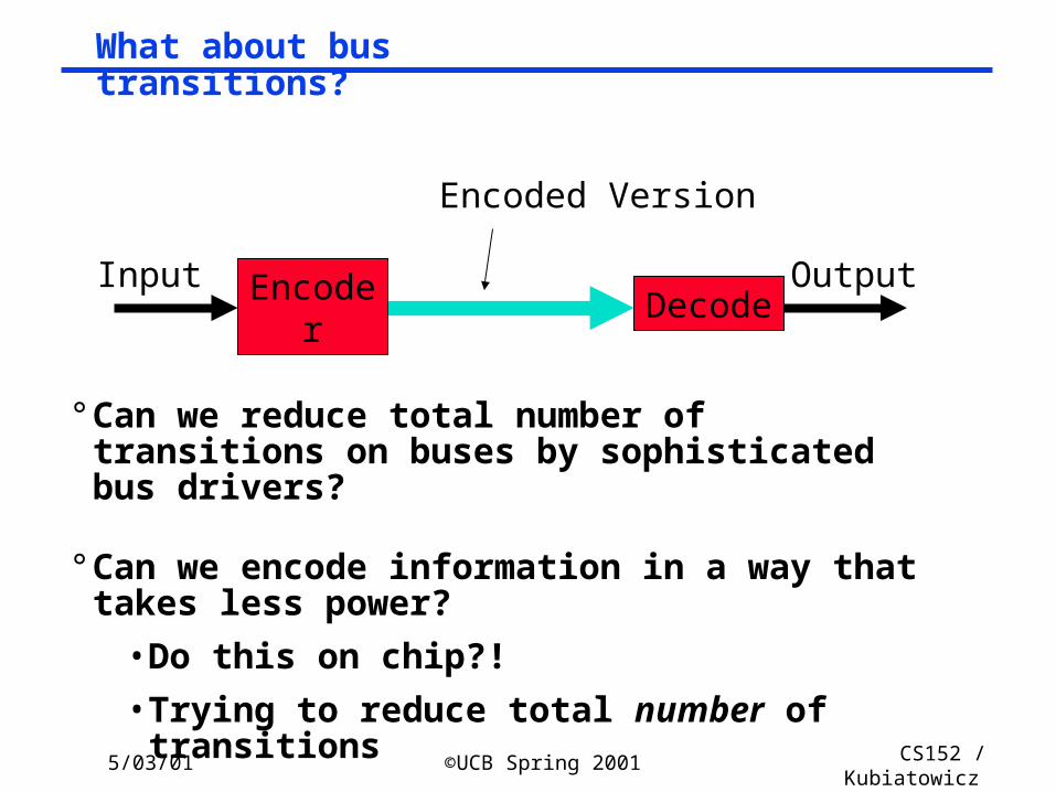
What about bus transitions?
° Can we reduce total number of transitions on buses by sophisticated bus drivers?
° Can we encode information in a way that takes less power?
• Do this on chip?!
• Trying to reduce total number of transitions
Encoded Version
Decode
Encoder
OutputInput
5/03/01 ©UCB Spring 2001 CS152 / Kubiatowicz
Lec26.48
Reasoning
° Increasing importance of wires relative to transistors• Spend transistors to drive wires more efficiently?
• Try to reduce transitions over wires
° Orthogonal to other power-saving techniques• I.e. voltage reduction, low-swing drive
• clock gating
• Parallelism (like vectors!)
5/03/01 ©UCB Spring 2001 CS152 / Kubiatowicz
Lec26.49
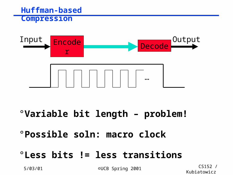
Huffman-based Compression
° Variable bit length – problem!
° Possible soln: macro clock
° Less bits != less transitions
…
Decode
Encoder
OutputInput
5/03/01 ©UCB Spring 2001 CS152 / Kubiatowicz
Lec26.50
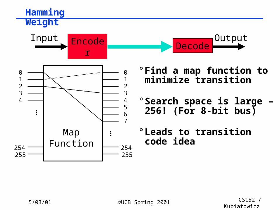
Hamming Weight
° Find a map function to minimize transition
° Search space is large – 256! (For 8-bit bus)
° Leads to transition code idea
…
01234
01234567
MapFunction
255254
255254
…
Decode
Encoder
OutputInput
5/03/01 ©UCB Spring 2001 CS152 / Kubiatowicz
Lec26.51
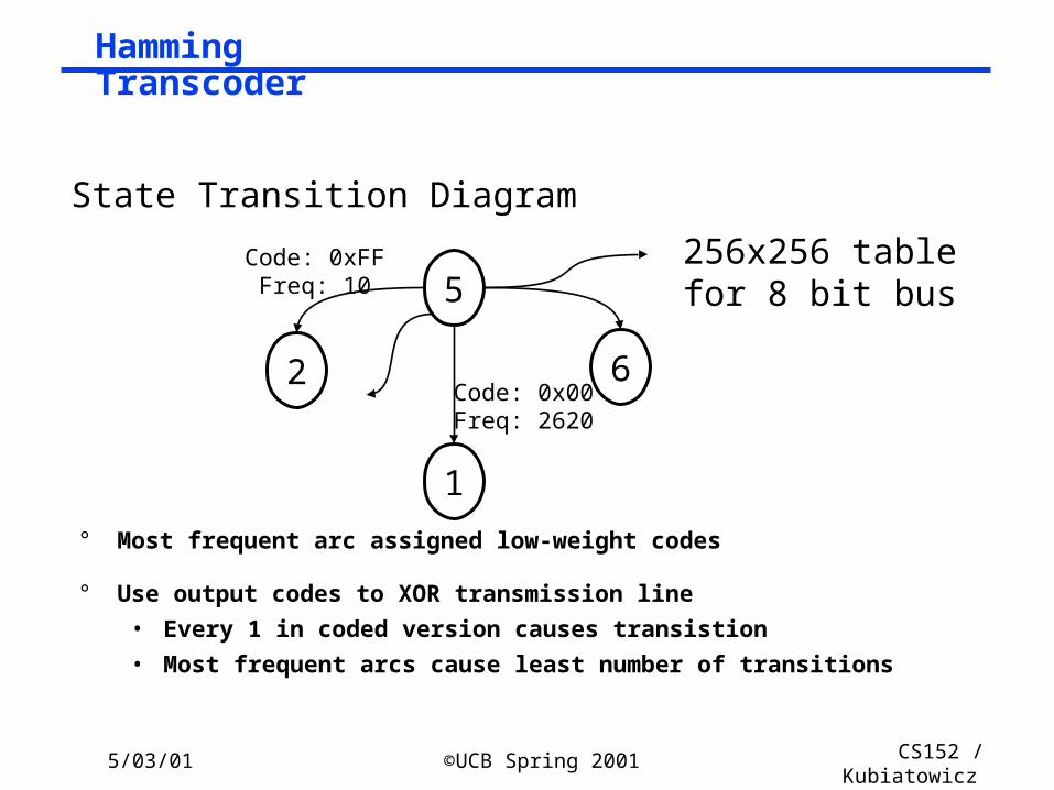
Hamming Transcoder
° Most frequent arc assigned low-weight codes
° Use output codes to XOR transmission line
• Every 1 in coded version causes transistion
• Most frequent arcs cause least number of transitions
5
6
1
2Code: 0x00Freq: 2620
Code: 0xFFFreq: 10
State Transition Diagram
256x256 tablefor 8 bit bus
5/03/01 ©UCB Spring 2001 CS152 / Kubiatowicz
Lec26.52
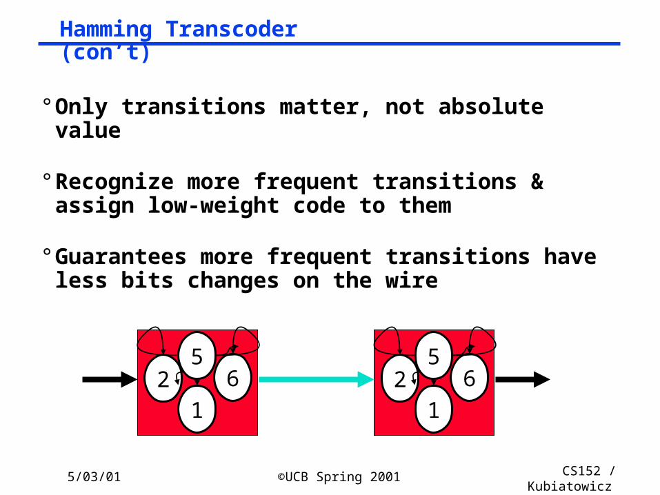
Hamming Transcoder (con’t)
° Only transitions matter, not absolute value
° Recognize more frequent transitions & assign low-weight code to them
° Guarantees more frequent transitions have less bits changes on the wire
56
12
56
12
5/03/01 ©UCB Spring 2001 CS152 / Kubiatowicz
Lec26.53
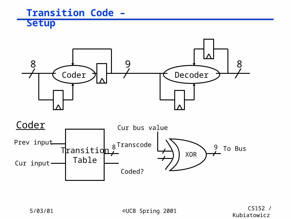
Transition Code – Setup
TransitionTable
Prev input
Cur input
Transcode8
Coded?
To Bus
Cur bus value
9XOR
Coder
Coder Decoder98 8
5/03/01 ©UCB Spring 2001 CS152 / Kubiatowicz
Lec26.54
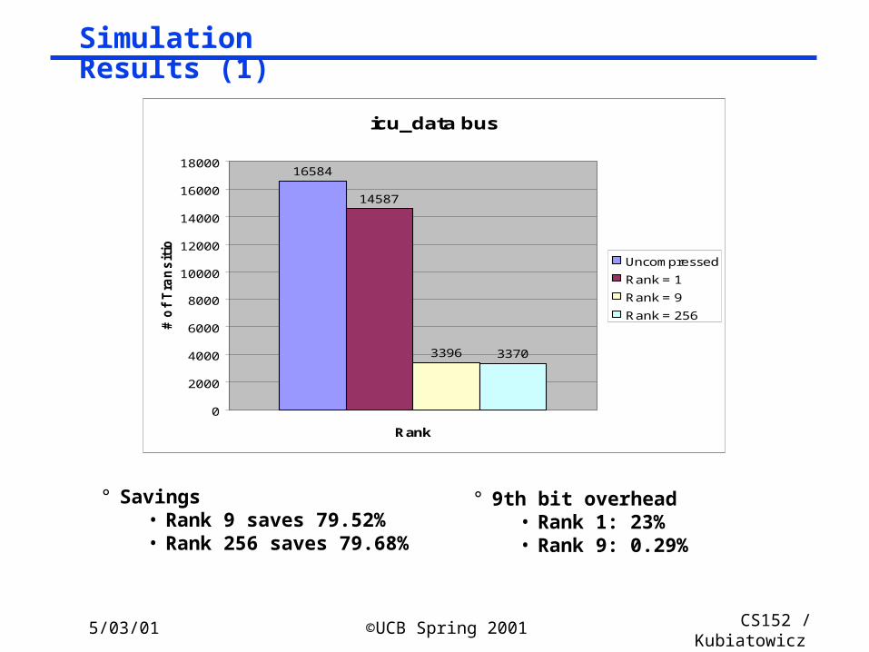
Simulation Results (1)
icu_data bus
16584
14587
3396 3370
0
2000
4000
6000
8000
10000
12000
14000
16000
18000
Rank
# o
f T
ran
sit
ion
s
Uncompressed
Rank = 1
Rank = 9
Rank = 256
° Savings• Rank 9 saves 79.52%• Rank 256 saves 79.68%
° 9th bit overhead• Rank 1: 23%• Rank 9: 0.29%
5/03/01 ©UCB Spring 2001 CS152 / Kubiatowicz
Lec26.55
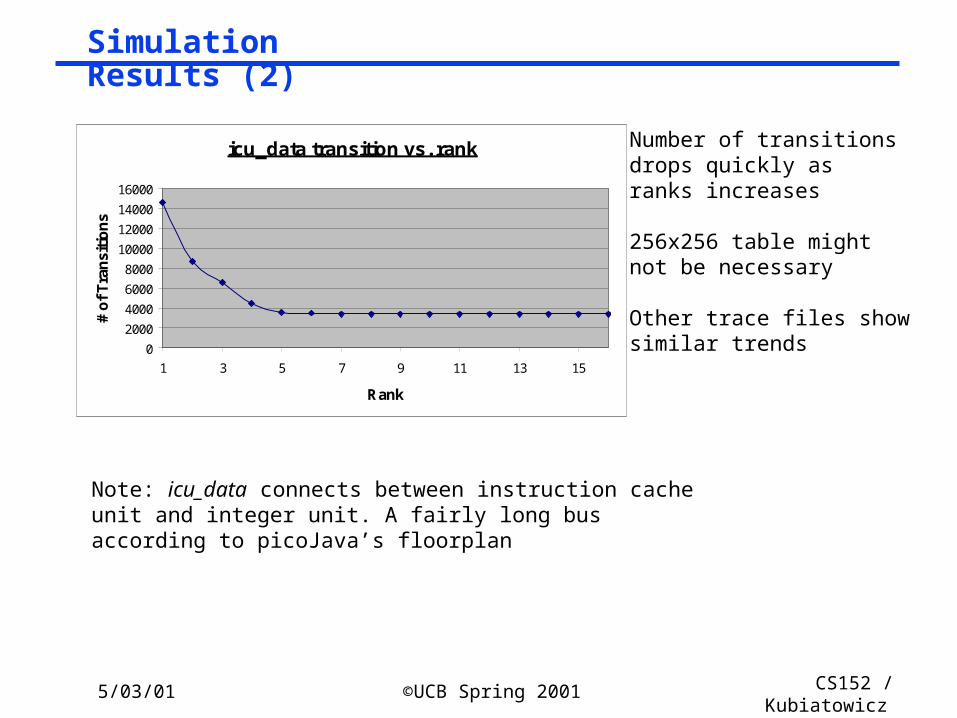
Simulation Results (2)
icu_data transition vs. rank
0
2000
4000
6000
8000
10000
12000
14000
16000
1 3 5 7 9 11 13 15
Rank
# o
f T
ran
siti
on
s
Number of transitionsdrops quickly asranks increases
256x256 table mightnot be necessary
Other trace files showsimilar trends
Note: icu_data connects between instruction cache unit and integer unit. A fairly long bus according to picoJava’s floorplan
5/03/01 ©UCB Spring 2001 CS152 / Kubiatowicz
Lec26.56
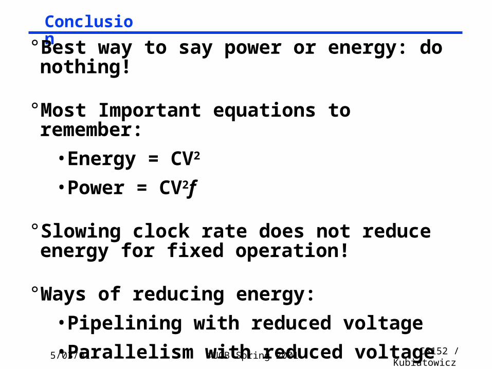
Conclusion° Best way to say power or energy: do nothing!
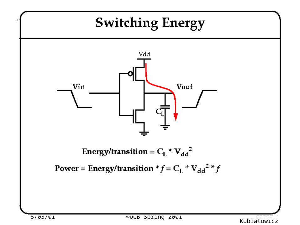
° Most Important equations to remember:
• Energy = CV2
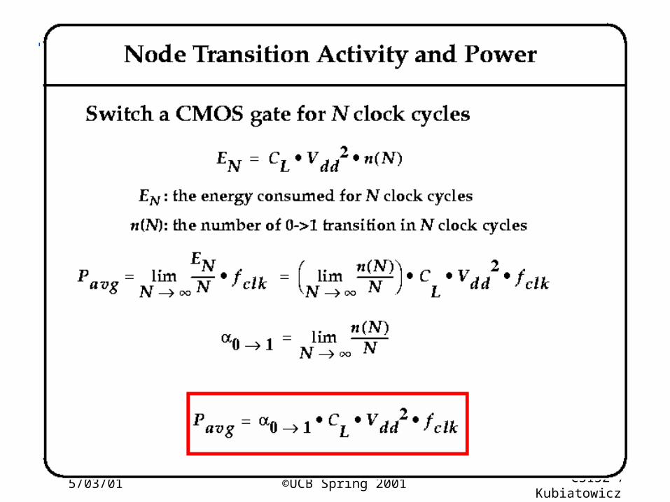
• Power = CV2f
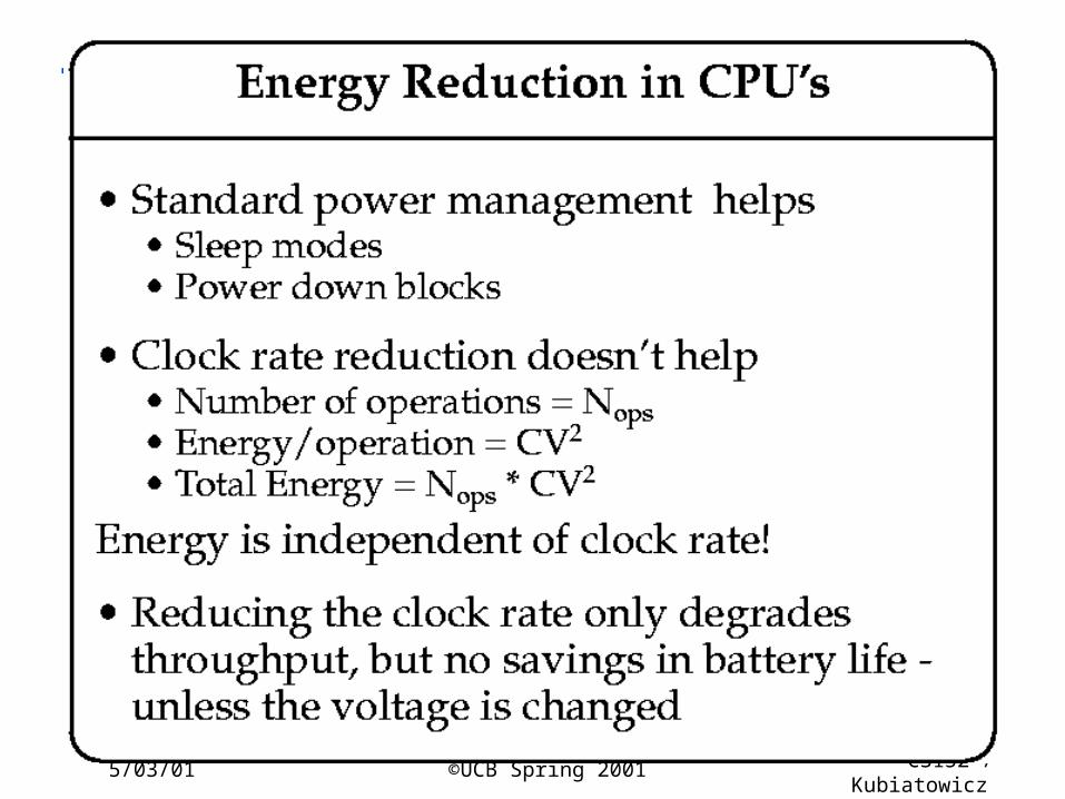
° Slowing clock rate does not reduce energy for fixed operation!
° Ways of reducing energy:
• Pipelining with reduced voltage
• Parallelism with reduced voltage