CS10, 11, 12, 20, 21, 24, 25, 40 & 41 SERIES · MUNCIE PTOs FOR THE ALLISON WORLD TRANSMISSION...
28
CD10 Series PTO CS10, CS41 Series PTO CS20 Series PTO MUNCIE PTOs FOR THE ALLISON WORLD TRANSMISSION CS10, 11, 12, 20, 21, 24, 25, 40 & 41 SERIES CLUTCH SHIFT PTO CD10, 30 & 40 SERIES CONSTANT DRIVE PTO PTO INSTALLATION AND OPERATOR’S MANUAL Muncie Power Products, Inc. KEEP IN VEHICLE READ OPERATING INSTRUCTIONS INSIDE BEFORE OPERATING PTO
-
Upload
phamnguyet -
Category
Documents
-
view
219 -
download
1
Transcript of CS10, 11, 12, 20, 21, 24, 25, 40 & 41 SERIES · MUNCIE PTOs FOR THE ALLISON WORLD TRANSMISSION...

CD10 Series PTO
CS10, CS41 Series PTO
CS20 Series PTO
MUNCIE PTOs FOR THE ALLISON WORLD TRANSMISSION
CS10, 11, 12, 20, 21, 24, 25, 40 & 41 SERIES
CLUTCH SHIFT PTO
CD10, 30 & 40 SERIESCONSTANT DRIVE PTO
PTO INSTALLATION AND OPERATOR’S MANUAL
Muncie Power Products, Inc.
KEEP IN VEHICLEREAD OPERATING INSTRUCTIONSINSIDE BEFORE OPERATING PTO
© Muncie Power Products, Inc. 2009
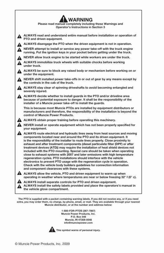
WARNINGPlease read manual completely including these Warnings and
Operator’s Instructions in Section 3
ALWAYS read and understand entire manual before installation or operation of PTO and driven equipment.ALWAYS disengage the PTO when the driven equipment is not in operation.NEVER attempt to install or service any power take-off with the truck engine running. Put the ignition keys in your pocket before getting under the truck.NEVER allow truck engine to be started while workers are under the truck.ALWAYS immobilize truck wheels with suitable chocks before working under truck.ALWAYS be sure to block any raised body or mechanism before working on or under the equipment.NEVER shift installed power take-offs in or out of gear by any means except by the controls in the cab of the truck.ALWAYS stay clear of spinning driveshafts to avoid becoming entangled and severely injured.ALWAYS decide whether to install guards in the PTO and/or driveline area because of potential exposure to danger. It shall be the responsibility of the installer of a Muncie power take-off to install the guards.This is because most Muncie PTOs are installed by equipment distributors or manufacturers and therefore, the responsibility of the installation is beyond the control of Muncie Power Products.ALWAYS obtain proper training before operating this machinery.NEVER install or operate equipment which has not been properly specified for your equipment.ALWAYS route electrical and hydraulic lines away from heat sources and moving components located near and around the PTO and its driven equipment. It is the responsibility of the installer to route lines properly. Close proximity to exhaust and after treatment components (diesel particulate filter (DPF) or after treatment devices (ATD)) may require the installation of heat shield devices not included with the PTO mounting. Special care should be taken when operating close to exhaust systems with 2007 and later emissions with high temperature regeneration cycles. PTO installations should interface with the vehicle electronics to prevent PTO usage with the regeneration cycle in operation. Check with the vehicle body builders guidelines for connection information and component clearances with these systems.ALWAYS allow the vehicle, PTO and driven equipment to warm up when operating in weather where temperatures are near or below freezing 32° f (0° c).ALWAYS install separate controls for PTO and driven equipment. ALWAYS install the safety labels provided and place the operators’s manual in the vehicle glove compartment.
The PTO is supplied with a packet containing warning labels. If you did not receive any, or if you need extra, you may order them, no charge, by phone, email, or mail. They are available through your nearest
Muncie distributor, or at the number and address below:
1-800-FOR-PTOS (367-7867) Muncie Power Products, Inc.
P.O. Box 548 Muncie, IN 47308-0548
This symbol warns of personal injury.

PTO INSTALLATION andOPERATOR’S MANUAL
MUNCIE PTOs FOR THE ALLISON WORLD TRANSMISSION
TABLE OF CONTENTSPTO Installation ...........................................................................Section 1PTO Installation Instructions .................................................................. 1.1
Clutch Shift with Remote Activation Solenoid (CS11/CS21/CS25/CS41) 1.4
Clutch Shift Electric/Hydraulic Shift System (CS10/CS40) ..................... 1.5
Clutch Shift Electric/Hydraulic Shift System (CS20/CS22/CS24/CS26) ... 1.7
Constant Drive (CD Series) Lube Installation ....................................... 1.10
Drag Brake Adjustment (CS10/CS20/CS22/CS24/CS26) ......................... 1.13
Driveshaft Installation ............................................................................ 1.13
Direct Mount Pump Installation ............................................................ 1.14
Optional Allison Interfacing ................................................................... 1.15
Operator’s Manual ......................................................................Section 2Power Take-Off Warranty ...................................................................... 2.1
PTO Shifting Procedures & Precautions ............................................... 2.2
Clutch Shift Operating Notes.................................................................. 2.3
PTO Maintenance ................................................................................... 2.4
PTO Torque & Horsepower Ratings ...................................................... 2.5
Trouble Shooting .........................................................................Section 3PTO Trouble Shooting Guide ................................................................. 3.1
SPD-1001D Trouble Shooting Guide ..................................................... 3.2
CONSTANT DRIVE SERIESCD10, CD30 & CD40
CLUTCH SHIFT SERIES CS10, CS11, CS20, CS21, CS22, CS24, CS25, CS26, CS40 & CS41

1.1
SECTION 1PTO INSTALLATION
PTO INSTALLATION INSTRUCTIONS
Always wear safety glasses. Read entire manual before starting installation.
1. There is a packet with the PTO which contains 4 WARNING LABELS. Before adhering the labels, make sure the surfaces are free of dirt and grease. Place the labels supplied as follows:
There are two (2) labels which measure approximately 4" x 8" which are to be placed on the outside of the vehicle frame rail, making them easy to be seen by anyone who might go under the truck or near the PTO. One label is to be placed on each side of the vehicle.
Should the body installed on the chassis cover the frame rail, place the label on the body in a position easily visible by anyone who might go under the vehicle or near the PTO. Do not paint over labels.
Figure 1
There are two (2) 4" X 8" labels supplied and one is to be placed on each side of the vehicle.

2. The 2" x 3" PTO Equipped Caution Label is to be placed within the cab of the vehicle and in clear view of the vehicle operator. It should be located near the PTO control, when the control is installed in the vehicle dash (See Figure 2). This label directs the operator to read the PTO operating instructions on the “Visor Label”. The Visor Label 4" x 6 ½" is to be placed on the visor on the operator’s side of the vehicle (See Figure 2). Do not mount this label on the same side of the visor as the air bag warning label, if so equipped. Vehicles with hydraulic dump pump are supplied with a warning label to be mounted in clear view of the operator while seated in the driver’s seat.
Figure 2
1.2
WARNING ADVERTENCIA! !
WARNING ADVERTENCIA! !
WARNING ADVERTENCIA! !
WARNING ADVERTENCIA! !
WARNING ADVERTENCIA! !
WARNING ADVERTENCIA! !
WARNING ADVERTENCIA! !
WARNING ADVERTENCIA! !
WARNING ADVERTENCIA! !
The 25mm (2) capscrews are to be used in positions 1 and 3 as show in diagram. The 30mm (6) capscrews and special lock washers are to be used for all other positions.
1.3
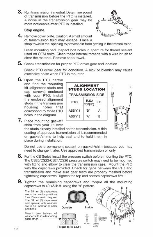
3. Run transmission in neutral. Determine sound of transmission before the PTO is installed. A noise in the transmission gear may be more noticeable after PTO is installed.
Stop engine. 4. Remove cover plate. Caution: A small amount
of transmission fluid may escape. Place a shop towel in the opening to prevent dirt from getting in the transmission.
Clean mounting pad. Inspect bolt holes in aperture for thread sealant used on OEM bolts. Clean these internal threads with a wire brush to clear the material. Remove shop towel.
5. Check transmission for proper PTO driver gear and location.
Check PTO driver gear for condition. A nick or blemish may cause excessive noise when PTO is mounted.
6. Open the PTO carton and find the mounting kit (alignment studs and cap screws) enclosed with your PTO. Install the enclosed alignment studs in the transmission housing holes that correspond to those PTO holes in the diagram.
7. Place mounting gasket/shim from your kit over the studs already installed on the transmission. A thin coating of approved transmission oil is recommended on gasket/shims to help seal and to hold them in place during installation.
Do not use a permanent sealant on gasket/shim because you may need to change it later. Use approved transmission oil only!
8. For the CS Series install the pressure switch before mounting the PTO. The CS20/CS22/CS24/CS26 pressure switch may need to be mounted with fitting and elbow to clear the transmission case. Mount the PTO with the capscrews provided. Check for gaps between the PTO and transmission and make sure gear teeth are properly meshed before tightening capscrews. Tighten the top and bottom capscrews first.
9. Tighten the remaining capscrews and torque all the mounting capscrews to 40-45 lb.ft. using the “x” pattern.
ALIGNMENTSTUDS LOCATION
TRANSMISSION SIDE PTO R.S./ L.S. TOP(HD)
ASS’Y 1 ‘B’ ‘A’
ASS’Y 3 ‘A’ ‘B’
Outside Inside
Mount two halves of washer with insides facing each other.
12 3
4 5
678
Torque to 45 Lb.Ft.

1.4
FOR THE CONSTANT DRIVE PTO GO TO STEP #11 10. Install the appropriate shifter kit components for Clutch Shift PTO, then
go to step #12.
CLUTCH SHIFT CS11/CS21/CS25/CS41 SERIES WITH REMOTE ACTIVATION SOLENOID
43TK4036 HOSE KIT (STANDARD)
** Clutchshift PTO requires connection to Allison “PTO Enable Input” circuit on Allison Gen. 4 controls. Check with vehicle dealer or body builder’s information for location.
** For Connection to Allison ECU
30T60223
“ ” “ ”’
¼⅝
⅛
7⁄16
⅛
“ ”
⅛
CAUTION:Install exhaust fitting into pipe thread port in end cover. Use pipe thread sealant only, DO NOT USE TAPE.Over-tightening this fitting into port may cause blockage and solenoid will not release PTO clutch pack.
CS EXHAUST PORT INSTALLATION

1.5
10. Continued. Install the appropriate shifter kit components for Clutch Shift PTO, then go to step #12.
CLUTCH SHIFT CS10/CS12/CS40 SERIESELECTRIC-HYDRAULIC SYSTEM 48TK3882
** Clutchshift PTO requires connection to Allison “PTO Enable Input” circuit on Allison Gen. 4 controls. Check with vehicle dealer or body builder’s information for location.
** For Connection to Allison ECU
-A
“ ” “ ”
’
7⁄16
“ ”
¼
’
’

1.6
CS10 (ONLY) BEARING COVER PORT IDENTIFICATION
** Clutchshift PTO requires connection to Allison “PTO Enable Input” circuit on Allison Gen. 4 controls. Check with vehicle dealer or body builder’s information for location.
** For Connection to Allison ECU
Blue
OrangeCTOTachometer Output
Muncie Overspeed Switch Option
SPD-1001A
34T40902 (Drop in )34T35872 (Screw in )
Connect to ORANGE Wire on SPD-1001A
-A
”“ ”“
’
”“
’
’
⅝
¼
3⁄16
1.7
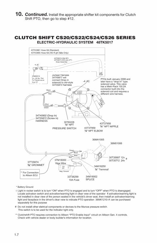
10. Continued. Install the appropriate shifter kit components for Clutch Shift PTO, then go to step #12.
CLUTCH SHIFT CS20/CS22/CS24/CS26 SERIESELECTRIC-HYDRAULIC SYSTEM 48TK5017
** Clutchshift PTO requires connection to Allison “PTO Enable Input” circuit on Allison Gen. 4 controls. Check with vehicle dealer or body builder’s information for location.
** For Connection to Allison ECU
48TK5017
34T35872 (Screw in)34T40902 (Drop In)
Jumper Harness34T40877 will connect Drop-in solenoid to old-style 34T35872 harness
PTOs built January 2008 and later have a “drop-in” type solenoid valve. This valve has a Metri-Pack 150.2A connector built into the solenoid coil and requires a different wire harness.
Green
Blue
Red
Black
#
-A
30T60228
“ ”“ ”
’
¼⅝
⅛
⅛⅛
7⁄16
’

1.8
CS20/CS22/CS24/CS26 BEARING COVER PORT IDENTIFICATION
** Clutchshift PTO requires connection to Allison “PTO Enable Input” circuit on Allison Gen. 4 controls. Check with vehicle dealer or body builder’s information for location.
** For Connection to Allison ECU
Muncie Overspeed Switch OptionJumper harness 34T40877 will connect “drop-in” solenoid to old-style 34T35872 harness.
PTOs built January 2008 and later have a “drop-in” type solenoid valve. This valve has Metri-Pack 150.2A connector built into the solenoid coil and requires a different wire harness.
34T40902 (Drop in )34T35872 (Screw in )
SPD-1001A
PTO Enable
CTOTachometer Output
Blue
Orange
MAIN PRESSUREPORT CONNECTION
PORT PLUGGEDNOT USEDMANUFACTURING ONLY
PORT PLUGGEDOPTIONAL PRESSUREPORT CONNECTION
PORT PLUGGEDNOT USEDMANUFACTURING ONLY
PRESSURE SWITCH PORT
#
Green
Blue
Red
Black Connect to Orange wire on SPD-1001A
-A
30T60228
“ ” “ ”
¼
⅝
⅛
3⁄16
’’

1.9
Transmission Main Pressure Connection
A
-4JIC
CONVERSION TO REMOTE ACTIVATION SOLENOIDCS10/CS20 SERIES INSTALLATION INSTRUCTIONS
Red
Black
IN
PS
CL
Blue
Green
Exhaust Line
Pressure Line
CONVERSION KIT 48TK4942
30T60228 Pressure Switch
34T35872 Wire Harness
43T37503⅛" NPT/JIC Fitting
43T35867⅛" NPT/JIC Elbow
45T36274Hose Assembly
45T36274Hose Assembly
43T36231Straight Branch Tee
M680147⁄16-20 Str. Elbow
35T37928Valve 12V D.C.
25T40727Cavity Plug
25T36726Str. Plug
25T36726Str. Plug
25T21684Pipe Plug
Plug
Exhaust Line
Plug
Pressure One Port, Plug Other Port
Cavity Plug
This kit is used to convert the standard built-in solenoid valve to a remote type without the replacement of the PTO end cover. 1. Remove the hydraulic lines attached to the PTO.2. Remove the solenid cartridge by first removing the stem nut, coil, and then the stem.3. Insert the cavity plug provided. 4. Remove the pipe plug from the PTO block identified as the exhaust line port.5. The pressure line can be connected to the port in the side as shown or in the port previously used by the pressure switch. The other port is plugged with ⅛" NPT plug.6. The pressure switch is moved to the solenoid block.7. The two straight threaded ports need to be plugged. One is plugged from the factory. (CS10 has only 1 port)8. Install the new hydraulic lines as shown in the drawing. 9. Use caution when mounting the solenoid block valve so that the coil is not placed in a bind against any surface. Use the
washers provided against the solenoid block.
19T36623Capscrew
22T35140Nut
21T37991Lockwasher
21T23153Washer
Block valve MUST BE spaced off any flat surface using washers to prevent damage to solenoid
CLUTCH SHIFT CS10/CS20/CS24 SERIESCONVERSION TO REMOTE ACTIVATION SOLENOID
CONVERSION KIT 48TK4942
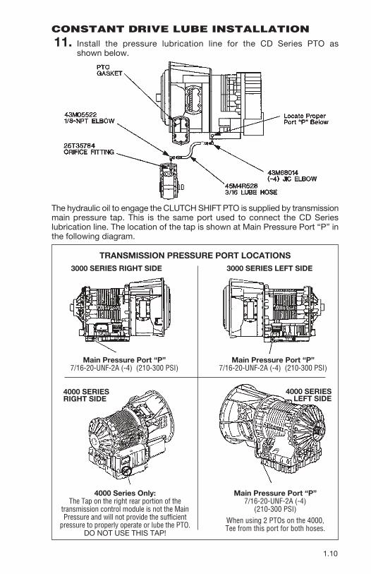
CONSTANT DRIVE LUBE INSTALLATION 11. Install the pressure lubrication line for the CD Series PTO as
shown below.
The hydraulic oil to engage the CLUTCH SHIFT PTO is supplied by transmission main pressure tap. This is the same port used to connect the CD Series lubrication line. The location of the tap is shown at Main Pressure Port “P” in the following diagram.
TRANSMISSION PRESSURE PORT LOCATIONS 3000 SERIES RIGHT SIDE 3000 SERIES LEFT SIDE
Main Pressure Port “P”7/16-20-UNF-2A (-4) (210-300 PSI)
Main Pressure Port “P”7/16-20-UNF-2A (-4) (210-300 PSI)
4000 Series Only:The Tap on the right rear portion of the
transmission control module is not the Main Pressure and will not provide the sufficient
pressure to properly operate or lube the PTO.DO NOT USE THIS TAP!
Main Pressure Port “P”7/16-20-UNF-2A (-4)
(210-300 PSI)When using 2 PTOs on the 4000, Tee from this port for both hoses.
4000 SERIESRIGHT SIDE
4000 SERIESLEFT SIDE
1.10
1.11
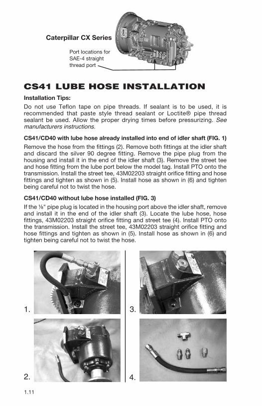
Installation Tips: Do not use Teflon tape on pipe threads. If sealant is to be used, it is recommended that paste style thread sealant or Loctite® pipe thread sealant be used. Allow the proper drying times before pressurizing. See manufacturers instructions.
CS41/CD40 with lube hose already installed into end of idler shaft (FIG. 1)Remove the hose from the fittings (2). Remove both fittings at the idler shaft and discard the silver 90 degree fitting. Remove the pipe plug from the housing and install it in the end of the idler shaft (3). Remove the street tee and hose fitting from the lube port below the model tag. Install PTO onto the transmission. Install the street tee, 43M02203 straight orifice fitting and hose fittings and tighten as shown in (5). Install hose as shown in (6) and tighten being careful not to twist the hose.
CS41/CD40 without lube hose installed (FIG. 3)If the ⅛" pipe plug is located in the housing port above the idler shaft, remove and install it in the end of the idler shaft (3). Locate the lube hose, hose fittings, 43M02203 straight orifice fitting and street tee (4). Install PTO onto the transmission. Install the street tee, 43M02203 straight orifice fitting and hose fittings and tighten as shown in (5). Install hose as shown in (6) and tighten being careful not to twist the hose.
CS41 LUBE HOSE INSTALLATION
1.
2.
3.
4.
Caterpillar CX Series
Port locations for SAE-4 straight thread port
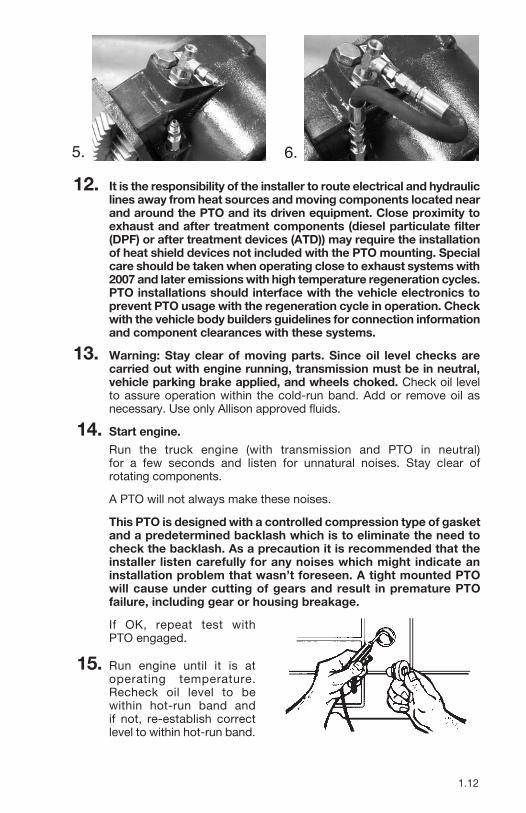
12. It is the responsibility of the installer to route electrical and hydraulic lines away from heat sources and moving components located near and around the PTO and its driven equipment. Close proximity to exhaust and after treatment components (diesel particulate filter (DPF) or after treatment devices (ATD)) may require the installation of heat shield devices not included with the PTO mounting. Special care should be taken when operating close to exhaust systems with 2007 and later emissions with high temperature regeneration cycles. PTO installations should interface with the vehicle electronics to prevent PTO usage with the regeneration cycle in operation. Check with the vehicle body builders guidelines for connection information and component clearances with these systems.
13. Warning: Stay clear of moving parts. Since oil level checks are carried out with engine running, transmission must be in neutral, vehicle parking brake applied, and wheels choked. Check oil level to assure operation within the cold-run band. Add or remove oil as necessary. Use only Allison approved fluids.
14. Start engine. Run the truck engine (with transmission and PTO in neutral)
for a few seconds and listen for unnatural noises. Stay clear of rotating components.
A PTO will not always make these noises.
This PTO is designed with a controlled compression type of gasket and a predetermined backlash which is to eliminate the need to check the backlash. As a precaution it is recommended that the installer listen carefully for any noises which might indicate an installation problem that wasn’t foreseen. A tight mounted PTO will cause under cutting of gears and result in premature PTO failure, including gear or housing breakage.
If OK, repeat test with PTO engaged.
15. Run engine until it is at operating temperature. Recheck oil level to be within hot-run band and if not, re-establish correct level to within hot-run band.
5. 6.
1.12

1.13
DRAG BRAKE ADJUSTMENT(CS10/CS20/CS24)
18. The CS Series PTO is supplied with an internal drag brake as standard (the CS40/41 does not have a drag brake.) The brake is set at the factory, but is field adjustable, should the output shaft continue to turn once the PTO is disengaged. Note: This brake will not stop the shaft if there is an abnormal occurrence or failure within the PTO clutch pack. Refer to the trouble shooting section for more information.
PROCEDURE:
1. Stop engine.2. Locate the adjustment screws on the end cover per the diagram.
3. Using a 3⁄16" Allen wrench turn each of the set screws ¼ turn clockwise, to increase brake drag.
4. Move away from under the vehicle and away from possible moving components and restart the engine. Look for the output shaft to stop turning. If the shaft continues to turn, then shut the engine off and repeat steps 2 thru 4.
SET SCREW ADJUSTMENT DRAG BRAKE SET SCREW
ADJUSTMENT DRAG BRAKE
16. Stop engine.Stay clear of rotating components and exhaust or engine components that could be hot. Inspect the cap screws to make sure they are properly tightened. All mounting bolts and nuts should be checked on a regular basis (for tightness). Check for leaks.
17. After complete installation, installers need to check for leaks and proper mounting torque on fasteners. Operate the equipment for an appropriate amount of time established for proper operation or per the equipment manufacturer’s recommendation. After shutting down equipment and engine, check for leaks. Allow unit to sit for 60 minutes and check for leaks. Fix any leaks found per manufacturer’s recommendations.
Muncie Power Products, Inc. is not responsible for any damage resulting from improper torquing of fasteners or improper maintenance of installation.
DIRECT MOUNT PUMP INSTALLATIONBefore bolting the pump to the PTO, place a non-seizing compound or grease on the PTO shaft and pump shaft.
All Muncie direct mount PTOs are supplied with the appropriate grease. Reusing an existing pump will require inspection of the pump splines. Clean any old grease from pump prior to installation.
When mounting hydraulic pumps weighing over 40 lbs.*, exceeding 12" in length, or for tandem, or multiple section pumps, a rigid support bracket must be installed. It should be attached to the rear of the pump and to the transmission to support the pump and to inhibit movement in all directions.
*weight includes fittings, oil, and unsupported hose sections.
This requirement does not take into account the system duty cycles, vehicle vibrations, application, terrain, and other external influences. We recommend that direct mounted components of any size or weight be supported when these conditions are extreme or unknown.
1.14
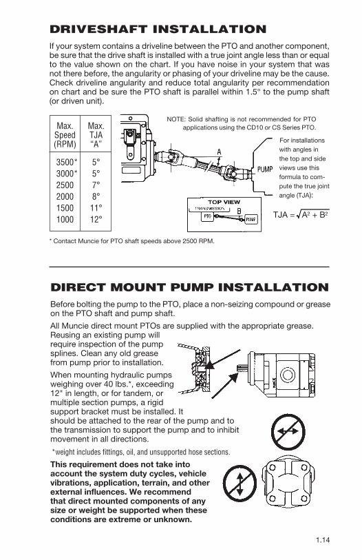
Max. Max. Speed TJA (RPM) “A”
*3500* 5° *3000* 5° 2500 7° 2000 8° 1500 11° 1000 12°
NOTE: Solid shafting is not recommended for PTO applications using the CD10 or CS Series PTO.
* Contact Muncie for PTO shaft speeds above 2500 RPM.
TJA = A2 + B2
For installations with angles in the top and side views use this formula to com-pute the true joint angle (TJA):
DRIVESHAFT INSTALLATIONIf your system contains a driveline between the PTO and another component, be sure that the drive shaft is installed with a true joint angle less than or equal to the value shown on the chart. If you have noise in your system that was not there before, the angularity or phasing of your driveline may be the cause. Check driveline angularity and reduce total angularity per recommendation on chart and be sure the PTO shaft is parallel within 1.5° to the pump shaft (or driven unit).

1.15
OPTIONAL ALLISON INTERFACE
Allison Transmission computers are equipped with the integrated electronic controls. The computer has available connections for PTO installers to allow for PTO enable, PTO overspeed control, and interlocks with other components of the vehicle. Instructions for these are available the Allison Service network and authorized dealers.
There are two versions of the controls. One is referred to as WTEC and has several release versions. The WTEC is found on vehicle prior to 2006. The other is referred to as Generation 4 (or Gen4) as is found on vehicles built in 2006 or later.
To enable the Allison optional controls you will need to make sure which system you have and which Allison vocational option is programmed into your control. For PTO operation the “PTO Enable” is a popular option. Clutchshift type PTOs mounted to transmissions with GEN 4 controls require the connection to the PTO enable circuit.
To identify which control you have you can look at the Allison shifter control as shown on the following page.
NOTICE: Direct mount pumps exceeding 40 lbs. or dump pumps and multiple section pumps must be supported with a heavy duty bracket attached with two bolts on the rear of the transmission and two points on the rear of the pump.
This recommendation is based upon our experiences to date. Bracket design illustrations and pump recommendations are to be used as GUIDELINES ONLY. Bracket design shown is representative and is not to be duplicated for all applications. Any failure as a result of damage caused by unsupported weight attached to the PTO will affect warranty considerations.
The photo below is an example of how the bracket is constructed. A bracket attached to two or more transmission bolts is required. Several transmission manufacturers have recommendations for attachments. Be sure to contact their website or technical representatives. The bracket design should assure that there is no stress or force exerted on the pump or PTO shaft.
If vertical supports are greater than 20 degrees off of perpendicular with the transmission main shaft then a reinforced “Z” bracket must be used. Reinforce horizontal members to prohibit flexing at bend or weld. Attach the bracket at the pump bolt closest to the center of gravity of the pump.
Most Muncie direct mount flanges offer multiple mounting bolt holes which allow the flange to be rotated to multiple locations on the PTO for improved port location or clearance. Be sure to torque the capscrew to 25 ft.lb., and it is advisable to use a thread locker to secure the capscrews (Loctite® 242 or NyLoc or equivalent).

PTO EnablePTO enable is optional on the WTEC systems, but can add the benefit of PTO overspeed control. Using the Allison Tech Data information and the vehicle’s Body Builder’s manuals the system can be integrated into the PTO activation or deactivation. The schematic is shown here.
1.16
WTEC III SIZELogo 1
WTEC III SIZELogo 2
4th Generation(Common)
4th Generation(Standard)
Also, the transmission control module (TCM) is different.
4th Gen TCM WTEC III ECU

1.17
For packages using wire 142, the PTO rocker switch must be changed or a relay will need to be used to apply current from wire 103 to wire 142. Switch or relay is not provided with PTO activation kit.
Additional wiring and programming options are available and schematics are available from Allison or through the vehicle dealer
IMPORTANT NOTE: SOME CONTROLLER GROUPS AND PACKAGES USE 142 WIRE FOR PTO ENABLE AND THISREQUIRES 103 WIRE BE CONNECTED TO THE 142 WIRE AS SHOWN HERE.
GEN 4Connection to the “PTO Enable Input” is required on the GEN 4 systems. This is because Allison changed the system and they modulate main transmission pressures. Making the connection for “PTO Enable” satisfies our requirement plus it adds the ability to program overspeed control into your application. (For additional information on programming refer to Allison Tech Data on their Extranet www.allisontransmission.com)
Allison transmission controls are programmed with application groups and packages. Contact dealer for package information. These packages can require different wiring options and you should verify which group and package you are connecting to before you install the PTO enable circuit. Most packages will connect using the wire 143 connection. For packages using wire 142, turn page.
SECTION 2OPERATOR’S MANUAL
POWER TAKE OFF WARRANTYThe Muncie Power Take-Off is warranted to be free of defects in material or workmanship and to meet Muncie’s standard written specifications at the time of sale. Muncie’s obligation and liability under this warranty is expressly limited to repairing or replacing, at Muncie’s option, within two years after date of original installation any defective part or parts or any product not meeting the specifications.
THIS WARRANTY IS IN LIEU OF ALL OTHER WARRANTIES, EXPRESSED OR IMPLIED. MUNCIE MAKES NO WARRANTY OF MERCHANTABILITY OR OF FITNESS FOR ANY PARTICULAR PURPOSE. MUNCIE’S OBLIGATION UNDER THIS WARRANTY SHALL NOT INCLUDE ANY TRANSPORTATION CHARGES OR COSTS OF INSTALLATION OR ANY LIABILITY FOR DIRECT, INDIRECT SPECIAL, INCIDENTAL, OR CONSEQUENTIAL DAMAGES OR DELAY. THE REMEDIES SET FORTH HEREIN ARE EXCLUSIVE, AND MUNCIE’S LIABILITY WITH RESPECT TO ANY CONTRACT OR SALE OR ANYTHING DONE IN CONNECTION THEREWITH, WHETHER IN CONTRACT, IN TORT, UNDER ANY WARRANTY, OR OTHERWISE, SHALL NOT, EXCEPT AS EXPRESSLY PROVIDED HEREIN, EXCEED THE PRICE OF THE PRODUCT OR PART ON WHICH SUCH LIABILITY IS BASED.
If requested by Muncie, products or parts for which a warranty claim is made are to be returned transportation prepaid to a Muncie Service Center. Any installation or use not in accordance with catalogue or package instructions, other improper use, operation beyond capacity, substitution of parts not approved by Muncie, use with equipment other than the equipment on which the Power Take-Off is first installed, or alteration or repair made to the Power Take-Off other than at a Muncie Service Center shall void this warranty. No employee or representative of Muncie is authorized to change this warranty in any way or to grant any other warranty.
2.1
2.2
PTO SHIFTING PROCEDURE PRECAUTIONS
PTO SHIFTING PROCEDURE & PRECAUTIONSPOWER TAKE-OFF OPERATION - VEHICLE STATIONARY
WARNING - parking brake must always be setWARNING - vehicle’s wheels must always be chockedWARNING - transmission must always be in neutral or parkWARNING - an operator must always be in the driver’s seat whenever the engine is running and the transmission is in gear, in order to prevent or stop any unexpected movement of the vehicle which may cause injuries to the operator or others in the vicinity.
• Read all operator’s manuals and instructions for the equipment that you are operating on this vehicle.
• Obtain instructions and training for all operations of the equipment on this vehicle including those not covered by this instruction booklet.
• Never work alone when repairing or going under a vehicle for repair or maintenance.• Always block any raised or moveable components or devices when working on or
around the vehicle as specified by the equipment manufacturer.• Warning: PTOs may drive driven equipment with an exposed drive shaft which may
cause severe injury or death if contacted.• Care must be taken when using a PTO for any specific application that the PTO has
been properly specified to match the transmission and auxiliary equipment. Improper specification and installation can cause severe damage to the vehicle transmission and the auxiliary components including driveshafts and driven equipment. Damaged components, equipment resulting in failure can cause serious personal injury to operators and persons in the vicinity.
• Always follow recommended procedures for selecting, installing, operating, or repairing a power take off as found in Muncie operator’s manuals, service parts lists and service manuals, catalogs, and application guides.
• Never use a Muncie PTO above the recommended operating speed of the unit or the specified driven unit.
• Never use a power take off that has not been specified for the output capabilities for the equipment being driven.
Rotating PTO drive shaftsIt is recommended that direct couple hydraulic pumps be used whenever possible, but if your application requires the use of an exposed drive shaft it is the responsibility of the installer and purchaser to determine the best installation of a guard.
• Rotating shaft can snag clothing, skin, hands, hair, etc. and will cause serious injury or death.
• Do not go under the vehicle when the engine is running.• Do not work near an exposed drive shaft with engine running.• Auxiliary shaft can be installed with recessed or protruding set screws. If raised, square
head setscrews are chosen, then be aware that this is a catch point for clothes, skin, hair, hands, etc. and serious injury or death may result.
The output shaft of a PTO with internal clutch packs may rotate in cold temperatures with the PTO disengaged. PTO shaft rotation can cause sudden movement of the output shaft and attached drive shaft leading to personal injury or death. Allow transmission to operate for a few minutes before engaging PTO. Allow PTO to operate for a few minutes before actuating application controls.
Some O.E.M. chassis manufacturers have integrated electronic controls which require certain conditions to be met before engaging a PTO. These include, but are not limited to setting parking brake, foot off service brake, engine at idle, foot off accelerator pedal, and/or transmission selector in park or neutral.

2.3
A power take-off is, and should be, operated as an integral part of the main transmission.
Failure to follow proper shifting or operating sequences will result in premature PTO failure with possible damage to the equipment.
Clutch Shift PTOs should not be engaged (turned “ON”) under heavy load and/or at PTO output shaft speeds over 1200 RPM.
Upon installation, Clutch Shift output shaft may operate in the off position. If this occurs, double check wiring as compared to the diagrams on pages 1.4 thru 1.8. If OK, drag brake adjustment may be required.
Drag Brake Adjustment is shown on page 1.11.
CLUTCH SHIFT OPERATING NOTESStart engine and with engine at idle or output shaft speed under 1200 RPM engage PTO. If PTO fails to operate or will not develop enough torque to operate your equipment, check pressures as follows:
a. Stop engine.
b. Install 400 PSI pressure gauge at the pressure inlet of PTO and a 400 PSI gauge at the pressure switch port or optional gage port as shown below.
c. Start engine. Stay clear of rotating components. Check gauge at inlet to PTO. If gauge registers less than 150 PSI, check for obstructions in the hoses or you may be connected to the wrong port on the transmission. Recheck the transmission information for the main pressure tap location on your model transmission (Page 1.9). If plumbing is correct then transmission should be inspected at an authorized Allison service center or dealer.
d. Place PTO switch in engage position. Stay clear of rotating components. If either gauge registers less than 150 PSI or if there is more than 50 PSI difference in the readings remove the solenoid valve and check the solenoid orifices, fittings and hoses for contamination.
e. If these suggestions do not improve the operation of the PTO then a catastrophic failure may have occurred and the PTO should be inspected at a Muncie service center.
FromTransmission
PressureSwitch Port
Pressure Inlet
2.4
PTO MAINTENANCEThe Power Take-Off, being an integral part of the transmission, should be serviced at the same intervals as the transmission. Changing transmission fluid in the transmission should follow the recommendation of vehicle manufacturer for severe service. Transmission oil level is important. Checking for PTO leaks and checking the transmission oil level should be done on a regular basis. Check for leaks upon delivery of the vehicle and after initial operation of your equipment. Loss of any oil can significantly affect or damage a transmission or PTO. Muncie Power Products, Inc. is not responsible for damage resulting from fasteners improper installation, mounting torque, or maintenance of the PTO.The Power Take-Off is also part of a system. The PTO system may include the activation control parts, a driveshaft, or hydraulic pump. This PTO system requires periodic checks and service. Typically the interval for maintenance checks of the PTO system depends on the application of the system. Every time the chassis is lubricated or a mechanic is under the vehicle the PTO system should be checked and serviced. For severe duty PTO system applications, it is recommended that the system be checked for service every 100 hours of use (this guideline can be adjusted based on past service history once you have it established.) This should include checking direct mount pump shaft connections. If pitting, galling, cracking, or deformation of splines has occurred then the PTO needs to be rebuilt or replaced.Within the first week of use, recheck the installation of the PTO. Check for leaks and loose mounting hardware (studs, cap screws, nuts). Recheck and tighten any loose connections. At regular maintenance intervals, check adjustments and lubricate moving parts, tighten and repair the connections, mounting hardware, cable or lever linkages.It is recommended that the operator/owner do a visual inspection for leaks under and around the vehicle and equipment on, at least, a weekly basis. Any leaks found should be corrected immediately.Pumps that are mounted directly to the PTO output shaft require the application of an anti-seize or a high temperature, high pressure grease. (Muncie PTOs are initially supplied with the required grease.) The purpose of this grease is to help make the PTO easier to service and to reduce the effects of fretting corrosion on the mating PTO and pump shafts. PTO applications under severe duty cycles and/or high torque requirements may require servicing this shaft connection by periodically re-greasing the shafts. Vehicles with low speed diesel engines are also severe applications due to the vibrations inherent in these vehicles. Fretting corrosion cannot be stopped by applying grease, the grease is only a deterrent. Transmission oil level is important. Check for PTO leaks and loose studs, cap screws or nuts and recheck oil level at regular intervals.
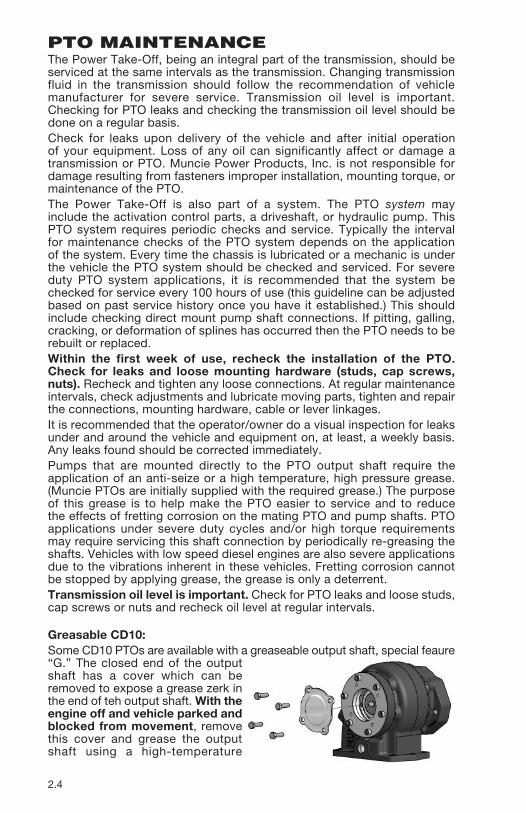
Greasable CD10:Some CD10 PTOs are available with a greaseable output shaft, special feaure “G.” The closed end of the output shaft has a cover which can be removed to expose a grease zerk in the end of teh output shaft. With the engine off and vehicle parked and blocked from movement, remove this cover and grease the output shaft using a high-temperature

2.5
PTO TORQUE & HORSEPOWER RATINGS
Intermittent service refers to an On/Off operation under load. If maximum horsepower and/or torque is used for extended periods of time, (5 minutes or more) this is considered “Continuous Service” and the horsepower rating of the PTO must be reduced as indicated in the note below.
INTERMIT. INTERMIT. PTO SPEED HP@1000 KW@1000 TORQUE TORQUE MAX SERIES RATIO RPM RPM LBS.FT. NM SPEED*
CD10 05 76 57 400 542 2500
CD10 06 73 54 385 522 2500
CD10 07 68 51 360 488 2500
CD10 08 64 48 336 456 2500
CD10 10 59 44 310 420 2500
CD30 05 95 71 500 678 2500
CD30 06 91 68 480 651 2500
CD30 05 95 71 500 678 2500
CD40 07 114 85 600 813 2500
CS10/11 05 95 71 500 678 2500
CS10/11 06 91 68 480 651 2500
CS10/11 07 86 64 450 610 2500
CS10/11 08 80 60 420 569 2500
CS10/11 10 73 54 385 522 2500
CS20/21/22/24/25/26 06 62 46 325 440 2500
CS20/21/22/24/25/26 07 58 43 305 414 2500
CS20/21/22/24/25/26 08 56 42 295 400 2500
CS20/21/22/24/25/26 10 55 41 290 393 2500
CS20/21/22/24/25/26 12 54 40 285 386 2500
CS40/41 07 114 85 600 813 2500
CS40/41 10 104 78 545 739 2500
CS40/41 12 93 70 490 664 2500
NOTE: For continuous service, multiply ratings shown by .70* Contact Muncie for applications requiring output shaft speeds above 2500 RPM.
high-pressure rated grease or an anti-sieze grease. One-half ounce of grease added with a grease gun at periodic intervals should be adequate for maintaining this shaft. After greasing, replace the cover over the shaft end.

3.1
SECTION 3TROUBLE SHOOTING
PTO TROUBLE SHOOTING GUIDE
PROBLEM
PTO doesn’t engage and is not receiving oil pressure at PTO Pres-sure switch port
PROBABLE CAUSE
• Overspeed switch operational.
• Solenoid Valve malfunctioning.
• Contamination in PTO activation lines.
REMEDY
• Refer to trouble shooting for SPD-1001D.
• With the ignition switch on (but engine not running) turn on the PTO control switch and listen for the solenoid valve. You should be able to hear the valve snap open. If not, check for a poor ground connection. This must be a bare metal contact to frame.
• Remove lines and clean. Remove solenoid and clean, or replace.
PTO doesn’t engage but is receiving oil pressure at PTO pressure switch port
• Clutch surfaces burned off due to high speed engagement or excessive load.
• Replace friction disks and plates. Engage PTO only at engine idle. Reduce PTO load.
PTO doesn’t disengage and is not receiving oil pressure at PTO pressure switch port
• Clutch surfaces seized due to improper engagement procedures or excessive load.
• Replace friction disks and plates. Reduce engagement RPM to below 1,000 rpm. Reduce PTO load.
PTO is noisy • Gears are worn. Overload-ing of PTO or long life.
• Replace gears or unit. Reduce load.
PTO housing breakage • PTO hit an object under the vehicle.
• Shock load caused by operating at relief pres-sure while oil is cold.
• Replace housing and install additional protection under vehicle.
• Replace housing and allow oil in hydraulic system to circulate and warm up before placing system in a loaded condition.
• Solenoid Valve malfunctioning.
• With the ignition switch on (but engine not running) turn on the PTO control switch and listen for the solenoid valve. You should be able to hear the valve snap open and close. If not then replace solenoid.
PTO doesn’t disengage and is constantly receiving oil pressure at PTO pressure switch port
ALL PTOS
CLUTCH SHIFT PTOS

3.2
SPD-1001A TROUBLE SHOOTING GUIDE
PROBLEM
Unit will not engage and overspeed light not on
PROBABLE CAUSE
• Blown fuse.
• Poor ground connection.
• Reverse polarity.
• Connection, splice or harness connection loose.
REMEDY
• See problem “blown fuse”.
• Check crimped and frame connections.
• Interchange red and black leads.
• Check crimped connections. Make sure pin connector is in proper alignment and ring tight.
TEST
No current at red wire.
Unit will not engage and overspeed light always on
• Alternator not engaged.
• Incorrect alterna-tor terminal.
• Poor or loose connection.
• Briefly run engine between 1,200-1,500 RPM.
• See diagram on alternator.
• Check crimp and connection of yellow wire.
Voltage at TACH jack does not in-crease with engine speed.
• Poor or loose connection.
• Unit out of adjustment.
• Check crimp and connection of green wire.
• See adjustment procedure.
Voltage at TACH jack does increase and decrease with engine speed.
• Unit out of adjustment.
• Faulty SPD-1001D.
• See adjustment procedure.
• Replace unit.
Voltage at green wire.
Unit will not disengage
• Poor connection. • Check crimped and ground connections.
Changes in voltage readings.
Intermittent operation
• Failed solenoid coil, shorted output lead, faulty SPD-1001D.
• Examine wiring harness and connections for possible short circuits. Check out replace faulty components.
Blown Fuse

201 East Jackson Street • Muncie, Indiana 47305800-367-7867 • Fax 765-284-6991
[email protected] • www.munciepower.comSpecifications are subject to change without notice.
Visit www.munciepower.com for warranties and literature.All rights reserved. © Muncie Power Products, Inc. (1995)
Member of the Interpump GroupIN95-02 (Rev. 01-17)