CS 672 1 Summer 2003 Lecture 5. CS 672 2 Summer 2003 IP Router Architecture A multiservice router...
49
CS 672 1 Summer 2003 Lecture 5
-
date post
19-Dec-2015 -
Category
Documents
-
view
220 -
download
0
Transcript of CS 672 1 Summer 2003 Lecture 5. CS 672 2 Summer 2003 IP Router Architecture A multiservice router...

CS 672
1
Summer 2003
Lecture 5
CS 672
2
Summer 2003
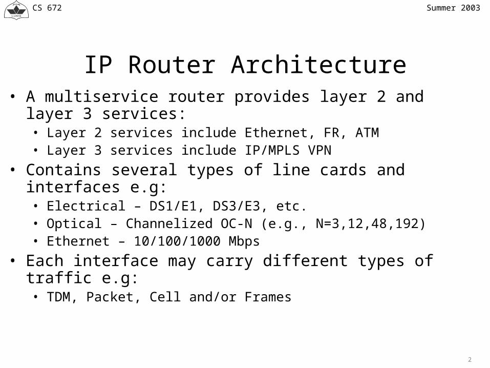
IP Router Architecture
• A multiservice router provides layer 2 and layer 3 services:• Layer 2 services include Ethernet, FR, ATM• Layer 3 services include IP/MPLS VPN
• Contains several types of line cards and interfaces e.g:• Electrical – DS1/E1, DS3/E3, etc.• Optical – Channelized OC-N (e.g., N=3,12,48,192)• Ethernet – 10/100/1000 Mbps
• Each interface may carry different types of traffic e.g:• TDM, Packet, Cell and/or Frames

CS 672
3
Summer 2003
IP Router Architecture
Forwarding
Forwarding
Line Card
Forwarding
Control Plane
Switch Fabric
Interfaces
Control Processor
Backplane

CS 672
4
Summer 2003
Cisco Multiservice Routers
C12000(GSR)
Cisco 7600
Cisco 10000 (ESR)

CS 672
5
Summer 2003
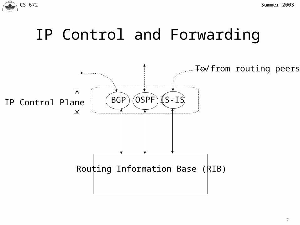
IP Control Plane
• IP router contains two interrelated but largely independent components:• Control Plane• Forwarding Plane
• IP control plane consists routing protocols such as:• IGP – OSPF, IS-IS, …• EGP – BGP4, …
• IP control plane provides routing information which is used to build the forwarding information base or forwarding table.

CS 672
6
Summer 2003
IP Forwarding Plane
• IP forwarding component uses forwarding table to obtained information necessary to transmit packets toward their destinations.
• Forwarding plane performs performs time-sensitive operations such as:• IP address lookup
• IP address lookup is usually one the most common bottlenecks in high performance routers.
CS 672
7
Summer 2003
IP Control and Forwarding
OSPF IS-ISBGPIP Control Plane
Routing Information Base (RIB)
To/from routing peers

CS 672
8
Summer 2003
IP Forwarding
• One of the main functions of IP routers is to forward packets.• To perform this task, routers make forwarding decision on each
packet.• IP Forwarding decision involves forwarding table lookup, using IP
destination address as the search key, to determine:• Next hop address• Outgoing link
• Using forwarding information, the packet is forwarded towards its destination.

CS 672
9
Summer 2003
IP Forwarding
Egress Link
headerIP Packet
Prefix Next hop Out Link
SwitchingForwarding Decision Scheduling
Address lookup
Ingress Link
Switch Fabric
Forwarding Table
Next Hop, Out Link

CS 672
10
Summer 2003
Centralized Forwarding Architecture
• Earlier generation routers used centralized forwarding models.• Control and forwarding components were centrally implemented on processor• Packet forwarding was done in software using central routing table.• The central forwarding model worked satisfactorily with slower link speeds
• As the link speed increased, the forwarding performance of the central forwarding architecture has to be increased.
• To exploit temporal and spatial of the IP traffic, routers heavily relied on route cache.
• Temporal locality means that there is a high probability of re-using a given IP address within short duration e.g.:• a sequence of packets for the same destination exhibit temporal locality

CS 672
11
Summer 2003
Cache-based Centralized Forwarding
• Spatial locality means that there is high probability of referencing address in certain range e.g.,• A sequence of packets with the same destination subnet exhibit spatial locality
• Cache is smaller but faster (access time < 50 ns) than the main memory (access time < 100ns)
• With route cache, • forwarding of one or more initial packets for a destination is based on slower
routing table. The result of IP address lookup are saved in the route cache• All subsequent packets for the same destination are the forwarded using faster
route cache• A common route cache performance metric is known as hit ratio
• Hit ratio indicates the percentage address lookups successfully found in the round cache

CS 672
12
Summer 2003
Cache-based Centralized Forwarding
• In general, hit ratio of a route cache depends upon:• degree of temporal and spatial locality of the IP traffic being forwarded, and• size of the route cache
• Route cache-based forwarding may be better suited for enterprise environment, where IP traffic exhibits more temporal/spatial locality and routing changes occur very infrequently.
• Performance of a route-based forwarding severely degrades in the Internet core.This is because:• Traffic in the core shows much less temporal/spatial locality• Routing changes are frequent (e.g., in the order of 100 route changes/sec)

CS 672
13
Summer 2003
Limitations of Cache-based Centralized Forwarding
• If the route changes too frequently,• Route cache entries need to be invalidated which amounts to reduction in hit ratio• Some studies have shown, hit ratio as low as around 50% to 70%.
• A lower hit ratio means:• A larger portion of traffic is forwarded based on slower routing table• The amount of redirected traffic could easily overload the processor• And processor overload in turn can cause system failure
• With the increase in Internet traffic,• routing table size,• link data rates, and• aggregate switching bandwidth requirement have also increased by several folds.

CS 672
14
Summer 2003
Limitations of Cache-based Centralized Forwarding
• Although link speeds have kept with the increasing traffic, however, forwarding capacity have not been able to do so.
• One of the main reasons for this can be attributed the bottleneck caused by IP address lookup operations.
• In addition to poor performance due to route cache, centralized forwarding architecture does not scale with the increase in• number of line cards,• link data rates, and• aggregate switching capacity
• This is because to be able to handle all traffic, centralized architecture would require increase in forwarding capacity in proportion to the aggregate switching capacity.

CS 672
15
Summer 2003
Distributed Forwarding Architecture
• Therefore, IP address easily becomes system bottleneck and limits aggregate forwarding capacity.
• Therefore, modern high-end routers are normally based on distributed forwarding architecture.
• In a distributed architecture, address lookup is implemented in each card.• Distributed forwarding scales better than centralized model because:
• each card only need to support forwarding that matches link rates rather than system aggregate capacity,
• line card forwarding capacity is a small fraction of system aggregate forwarding capacity, and
• address lookup becomes relatively easier

CS 672
16
Summer 2003
Distributed Forwarding Architecture
• Distributed forwarding architecture relies on separation of time-critical forwarding plane and less time-critical control plane tasks to achieve scalability.
• Thus distributed forwarding model makes it possible to:• decentralize time-critical IP forwarding plane tasks, and• centralize less time-critical IP control plane tasks
• This means, forwarding plane tasks can be optimized independently on each line card according to the link rates.
• As a result, router forwarding capacity scales with the aggregate switching bandwidth and link data rates.

CS 672
17
Summer 2003
Routing Information Base (RIB)
• The decoupling of control/forwarding and distributed nature of forwarding means:• Router needs to maintain two separate databases namely RIB and FIB
• The RIB (or routing table) maintains user supplied static and routing protocol provided dynamic routes
• RIB may contain multiple routes for a destination• routes from different protocols or• routes from the same protocol but different metric values
• A path consists of outgoing interface to a next hop.• RIB may have one or more paths for each destination.

CS 672
18
Summer 2003
Forwarding Information Base (FIB)
• Not all routes maintained by RIB are feasible routes.• FIB is a subset of RIB since it only maintains feasible routes that can be
actually used for forwarding.• FIB is differs from route cache in following aspects:
• Route cache only maintains a small number of most recently used routes• FIB maintains all accessible routes (i.e., it is a mirror image of RIB)• Route cache may need to invalidate its entries frequently in a dynamic routing
environment resulting in performance degradation.• Because FIB mirrors the RIB, its performance does not degrades in a dynamic
routing environment.

CS 672
19
Summer 2003
Forwarding Information Base (FIB)
• A FIB entry contains all the necessary information for forwarding a packet towards its destination e.g.:• IP destination address, Next hop, Out Interface Layer 2 Header information
• A FIB entry maps an destination IP address to a single or multiple paths• With multiple paths, traffic for a given destination can be forwarded over
multiple paths.• The capability to forward traffic over multiple paths is known as load-
balancing.• Standard packet scheduling algorithms such as RR and WRR can be used
to load-balance traffic over multiple paths.

CS 672
20
Summer 2003
Forwarding Information Base (FIB)
• FIB forms the time-critical forwarding plane path through a router.• To have a scalable forwarding architecture, in terms of number of address
prefixes (or FIB entries) and data rates, an efficient representation and lookup scheme is crucial for the FIB.
• In particular, we would like to have a scheme with fastest lookup time and lowest memory consumption.• In contrast, RIB needs to be optimized for smallest updates times to handle route
changes quickly. • The adaptability of Mtrie-based schemes for wide range of HW/SW
environments, make them attractive for RIB and FIB implementations.

CS 672
21
Summer 2003
OSPF IS-ISBGP
RIB
FIB
IP Control Plane
Control Processor Card
FIB FIB
Switch Fabric
Line Cards
Links Links
Forwarding Plane
Routing information to/from peers
1
2
3
4 4

CS 672
22
Summer 2003
Distributed FIB
1. Receive routes information's2. Select the best feasible routes3. Distribute the feasible routes to FIB on the line cards4. Initially, synchronize the entire FIB. Afterwards, resynchronize
incrementally as routing info changes

CS 672
23
Summer 2003

CS 672
24
Summer 2003
Forwarding Equivalence Class (FEC)
• Conventional IP forwarding makes hop-by-hop forwarding decision along the path traversed by the packet.• IP forwarding maps each destination IP address to a next hop router address and an outgoing
link• Multiple IP destination address are mapped to a next hop/outgoing link (i.e., many-to-one
mapping).• As far as IP forwarding is concerned, group of IP destination addresses that get
mapped to the the same set of IP destination addresses are indistinguishable.• For example, they are forwarded along the same path

CS 672
25
Summer 2003
Forwarding Equivalence Class (FEC)
• A group of packets (possibly belonging to different IP destination) that are identically with respect to forwarding decision (e.g., forwarded in the same way and along the same path) is said to form a FEC.
• In IP forwarding, routers assign and reassign each packets to certain FEC on every hop.• For example, two packets with different IP destination addresses are mapped to the same FEC if
there is a common longest prefix entry.• These packets would continue to traverse the same path as long as they share a common FEC.
• When a set of packets with different destination addresses traverse a network, each router may assign them to the same or different FEC(s) based on forwarding information.

CS 672
26
Summer 2003
R3 R5
R1
R2 R4
R6
Prefix Next hop Out Link
d1,d2 R4 Link 2
Prefix Next hop Out Link
d1,d2 R2 Link 1
Prefix Next hop Out Link
d1 R6 Link 1
d2 R5 Link 2
d1d2d1d2
d1d2d1
d1
d2d1
d1
d2d2
d1 and d2 mapped to different FECs
d1 and d2 mapped to the same FEC
d1 and d2 mapped to the same FEC
Destination = d2
Destination = d1
FEC

CS 672
27
Summer 2003
IP Packet forwarding
• IP forwarding• IP forwarding is done independently at every hop• IP forwarding decision is made on:
Packet header Routing algorithm output (routing table)
• Each IP hop runs its own instance of the routing algorithm• Each IP hop makes its own forwarding decisions

CS 672
28
Summer 2003
IP Address Lookup (bottleneck)
• IP lookup forms a major bottleneck in high performance routers.• This is further made worse by the fact that IP forwarding requires complex
lookup operation at every hop along the path.• So, we could identify the FECs and associate each packet to certain FEC, we
would be able to either avoid or simplify IP address lookup operation.• Supposing such a scheme does exist, then, a router would be able to make
equivalent forwarding decision using new information other than IP destination address.

CS 672
29
Summer 2003
MPLS
• In this context, one method to avoid IP address lookup bottleneck is to carry extra information, known as label, in the packet header.
• The forwarding scheme (technology) that uses label information for making packet forwarding decision is called Multiprotocol Label Switching (MPLS).
• Thus MPLS avoids (ignoring the ingress/egress routers) the IP address lookup operation for make forwarding decision.

CS 672
30
Summer 2003
MPLS
• MPLS: Multi Protocol Label Switching • Packet forwarding decision is made using label-based lookups• MPLS nodes forward packets using label rather than the IP destination address• Labels are assigned to packets at the ingress to the MPLS network• In the MPLS network (i.e., MPLS transit nodes) packets are forwarded based on label
information. No further packet analysis Label swapping (label in/label out)
• Labels are carried in packet header

CS 672
31
Summer 2003
MPLS forwarding: FEC and Next-Hop
• MPLS makes use of FECs• MPLS nodes assign a label to each FEC• Packet classification (into a FEC) is done where the packet enters the
MPLS network• No sub-sequent packet classification in the MPLS network

CS 672
32
Summer 2003
MPLS Labels
• Short fixed length value that identifies a particular FEC.• The association of a label to a FEC is known as label-to-FEC binding.• Label of an incoming packet is known as in or local label• Label of an outgoing packet is known as an out or remote label.• A packet may contain:
• Both in and out labels• In label but no out label• Out label but no in label

CS 672
33
Summer 2003
MPLS Labels
Label = 20 bits Exp = Experimental, 3 bits S = Bottom of stack, 1bitTTL = Time to live, 8 bits
0 1 2 30 1 2 3 4 5 6 7 8 9 0 1 2 3 4 5 6 7 8 9 0 1 2 3 4 5 6 7 8 9 0 1
Label | Exp|S| TTL

CS 672
34
Summer 2003
Label Stack
• A MPLS packet may contain one or more labels which are referred to as label stack. • Labels in a label stack are organized Last-In-First-Out (LIFO) ordered sequence.• The number of entries in the label stack represent the stack depth.• Label of an incoming packet is known as in or local label• A label stack of depth d represents an ordered sequence of labels <1,2,3,…,d-1,d>,
where 1 is at the bottom of the stack and d at the top.• An unlabeled packet may be viewed as a packet with label stack of depth 0.

CS 672
35
Summer 2003
Label Stack
Label Stack Entry Level 1
Level 2
Level d-1
Level d
Label Stack Entry
Label Stack Entry
Label Stack Entry
Bottom of the Stack
Top of the Stack

CS 672
36
Summer 2003
Label Stack Operations
• MPLS always forward packets based on the value of the in label at the top of the stack• For an incoming packet, other than examining the top label of the stack to index the label
forwarding table no other operations are performed.• For an outgoing packet, however, MPLS node performs one or more label operations such as:
• Pop Remove the top label
• Swap Replace the top label with a new one
• Push Add a specified number of label entries at the top of the stack.

CS 672
37
Summer 2003
Label Stack
171.68.10/24
LSR1
Next-HopNext-Hop
In In LabLab
55
......
Address Address PrefixPrefix
171.68.10171.68.10
......
OutOutI/FI/F
11
......
Out Out LabLab
77
......
In In I/FI/F
00
......
IP packetD=171.68.10.12
Label = 5
Label = 21
IP packetD=171.68.10.12
Label = 7
Label = 21
• LSR1 forwards the labelled packet based on the label at the top of the label stack

CS 672
38
Summer 2003
Label Switching Router (LSR)
• Router that support MPLS are known as label switching routers (LSRs).• LSR can be ATM switch or a router

CS 672
39
Summer 2003
Downstream and Upstream LSRs
• Note: an LSR may be upstream with respect to certain FEC and downstream for another.
Packets with IP destination = 172.68.10/10and carrying label L1
172.68.10/24
LSR1 LSR2
Upstream Downstream

CS 672
40
Summer 2003
Label Distribution Modes
• In MPLS, it is always the downstream LSR that assigns the FEC-to-label bindings and distribute them to the upstream LSR.
• The downstream LSR distributes bindings in two ways:• On explicit request from the upstream LSR• Unsolicited
• The label distribution mode when the upstream LSR makes an explicit request for label-to-FEC bindings is known as downstream-on-demand (DoD).
• The label distribution mode when the downstream LSR distributes label-to-FEC bindings without explicit requests from the upstream LSR is known as downstream-unsolicited (DU).

CS 672
41
Summer 2003
Downstream on demand distribution
• LSRs assign a label to each FEC• Upstream LSRs request labels to downstream neighbors• Downstream LSRs distribute labels upon request
172.68.10/24
LSR1 LSR2
Use label 5 for destination 171.68.10/24
Request label for destination 172.68.10/24

CS 672
42
Summer 2003
Downstream unsolicited
• LSRs assign a label to each FEC• Downstream LSRs distribute labels unsolicited
172.68.10/24
LSR1 LSR2
Use label 5 for destination 171.68.10/24

CS 672
43
Summer 2003
Label Distribution Protocols
• The protocols that are used to request and distribute label-to-FEC bindings are known as label distribution protocols.
• MPLS architecture defines several label distribution protocols i.e.:• LDP
Maps unicast FECs (e.g., IP destinations) into labels• BGP
External labels (e.g., VPN routes)• RSVP
Traffic engineering and resource reservation• CR-LDP
Traffic engineering and resource reservation

CS 672
44
Summer 2003
Edge and Core LSRs
• MPLS network consists of interconnection of LSRs.• The contiguous set of LSRs form a MPLS domain
• The LSRs at the edge of the MPLS network are referred to as edge LSRs. Edge LSRs perform following functions:• label imposition as traffic enters the MPLS network• label disposition as traffic leaves the MPLS network
• The non-edge LSRs are known as core (or transit) LSRs.• Core LSRs only forward labeled packets.

CS 672
45
Summer 2003
MPLS Network
IGP domain with a label distribution protocol
Edge LSR
Edge LSR
Core LSRMPLS Network

CS 672
46
Summer 2003
Label Switched Path (LSP)
• Each labelled packet• enters the MPLS network in the ingress LSR• exits the MPLS network in the egress LSR
• LSP is the sequence of LSRs through which the labelled packets have to go through in order to reach the egress LSR.
• LSPs are unidirectional, therefore, for bi-directional traffic flows, two LSPs are required.
• LSPs are established via label distribution protocols such as LDP, RSVP-TE, and BGP.

CS 672
47
Summer 2003
Label Switched Path (LSP)
• LSR-ingress to LSR-egress path is the same for packets of the same FEC
• LSPs are unidirectional• Return traffic requires another LSP
IGP domain with a label distribution protocol
Ingress-LSR
Egress-LSR
LSP

CS 672
48
Summer 2003
Hierarchical LSPs
• Using label stack mechanism, it is possible to nest one or more LSPs within another LSPs.
• LSPs that contain other LPS are referred to as hierarchical LSPs.• Hierarchical LSPs are similar to Virtual Paths in ATM.
• A LSP of depth d is defined as a sequence of LSRs which:• starts at an LSR (i.e., LSP ingress) that pushes on a level d label, and• terminates at an LSR (i.e., LSP egress) where packet is forwarded based on a label
stack of depth d-1.

CS 672
49
Summer 2003
Hierarchical LSP
LSP1
LSP2
LSP3
Ingress LSR for LSP1
Egress LSR for LSP1
Ingress LSR for LSP3
Hierarchical LSP (Label stack)