CS 151 Digital Systems Design Lecture 20 Sequential Circuits: Flip flops.
16
CS 151 Digital Systems Design Lecture 20 Sequential Circuits: Flip flops
-
date post
21-Dec-2015 -
Category
Documents
-
view
220 -
download
2
Transcript of CS 151 Digital Systems Design Lecture 20 Sequential Circuits: Flip flops.
CS 151
Digital Systems Design
Lecture 20Sequential Circuits: Flip flops
Overview
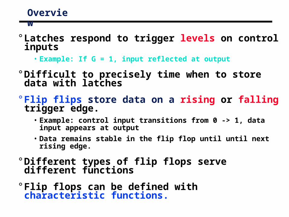
° Latches respond to trigger levels on control inputs• Example: If G = 1, input reflected at output
° Difficult to precisely time when to store data with latches
° Flip flips store data on a rising or falling trigger edge.• Example: control input transitions from 0 -> 1, data input appears at
output
• Data remains stable in the flip flop until until next rising edge.
° Different types of flip flops serve different functions
° Flip flops can be defined with characteristic functions.
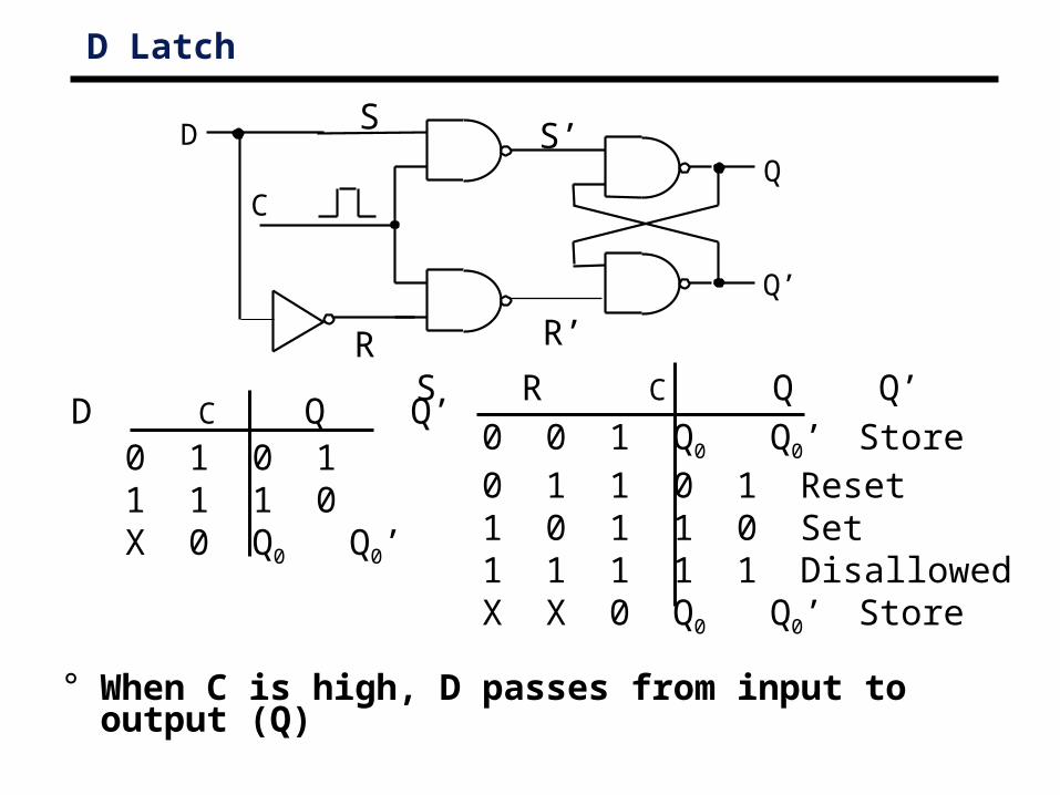
D Latch
Q
Q’
C
D S’
R’
S
R S R C Q Q’
0 0 1 Q0 Q0’ Store 0 1 1 0 1 Reset1 0 1 1 0 Set1 1 1 1 1 DisallowedX X 0 Q0 Q0’ Store
0 1 0 11 1 1 0X 0 Q0 Q0’
D C Q Q’
° When C is high, D passes from input to output (Q)
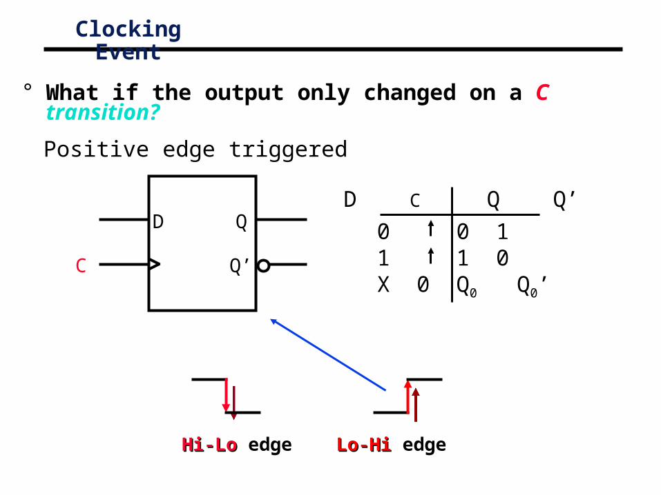
Clocking Event
Lo-HiLo-Hi edgeHi-LoHi-Lo edge
° What if the output only changed on a C transition?
C
D Q
Q’
0 0 11 1 0X 0 Q0 Q0’
D C Q Q’
Positive edge triggered
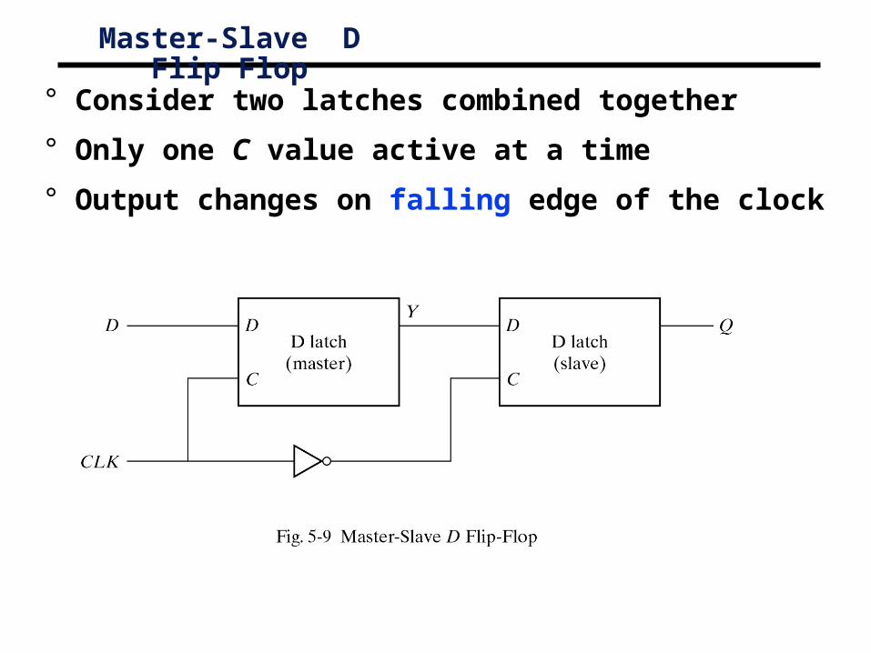
Master-Slave D Flip Flop
° Consider two latches combined together
° Only one C value active at a time
° Output changes on falling edge of the clock
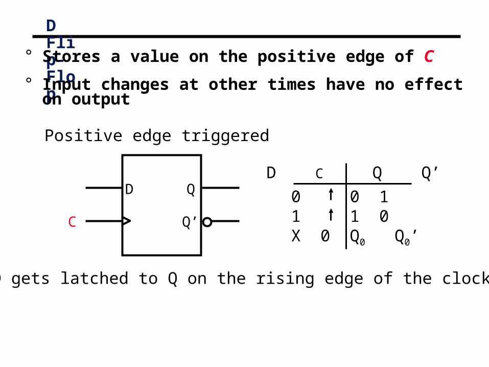
D Flip-Flop
D gets latched to Q on the rising edge of the clock.
° Stores a value on the positive edge of C
° Input changes at other times have no effect on output
C
D Q
Q’
0 0 11 1 0X 0 Q0 Q0’
D C Q Q’
Positive edge triggered
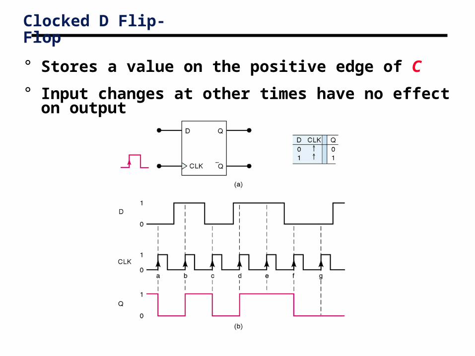
Clocked D Flip-Flop
° Stores a value on the positive edge of C
° Input changes at other times have no effect on output
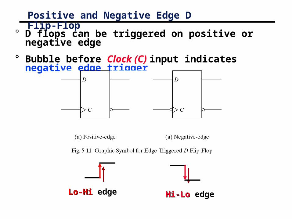
Positive and Negative Edge D Flip-Flop
° D flops can be triggered on positive or negative edge
° Bubble before Clock (C) input indicates negative edge trigger
Lo-HiLo-Hi edge Hi-LoHi-Lo edge
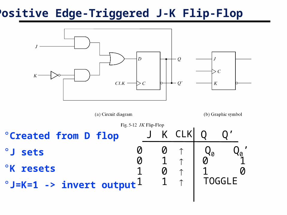
Positive Edge-Triggered J-K Flip-Flop
0 0 Q0 Q0’ 0 1 0 1 1 0 1 0 1 1 TOGGLE
Q J Q’CLK K °Created from D flop
°J sets
°K resets
°J=K=1 -> invert output
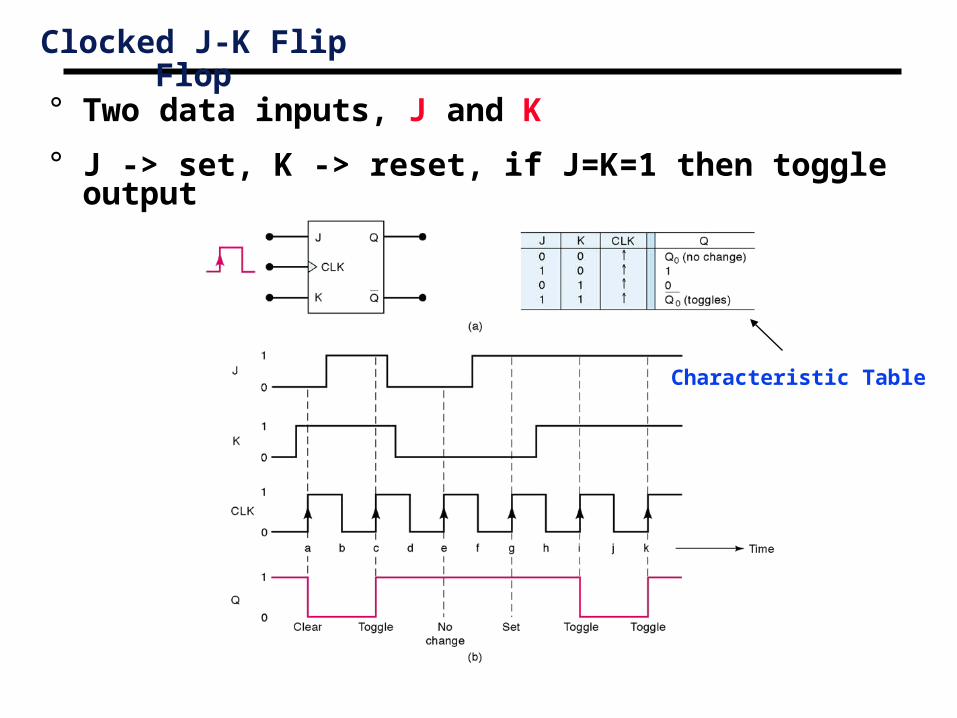
Clocked J-K Flip Flop
° Two data inputs, J and K
° J -> set, K -> reset, if J=K=1 then toggle output
Characteristic Table
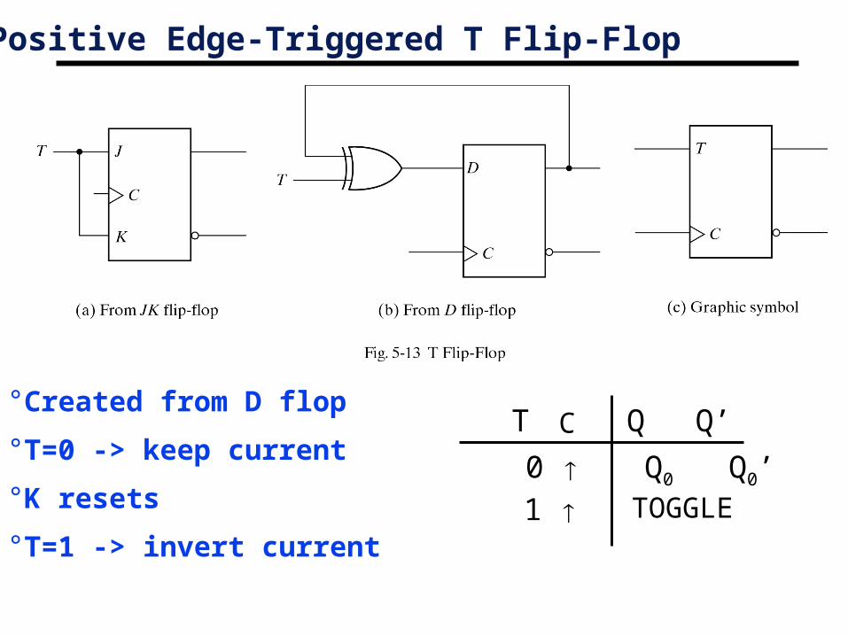
Positive Edge-Triggered T Flip-Flop
0 Q0 Q0’ 1 TOGGLE
Q Q’C T °Created from D flop
°T=0 -> keep current
°K resets
°T=1 -> invert current
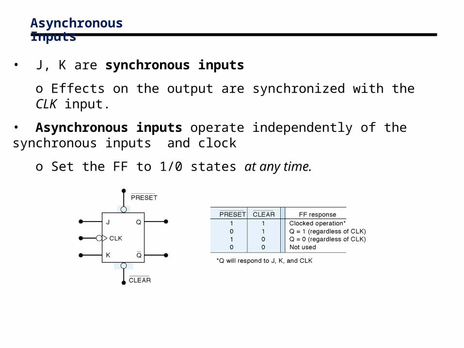
Asynchronous Inputs
• J, K are synchronous inputs
o Effects on the output are synchronized with the CLK input.
• Asynchronous inputs operate independently of the synchronous inputs and clock
o Set the FF to 1/0 states at any time.

Asynchronous Inputs
Asynchronous Inputs
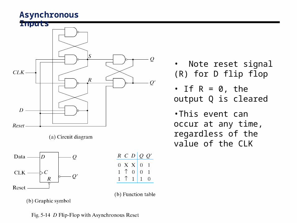
• Note reset signal (R) for D flip flop
• If R = 0, the output Q is cleared
•This event can occur at any time, regardless of the value of the CLK
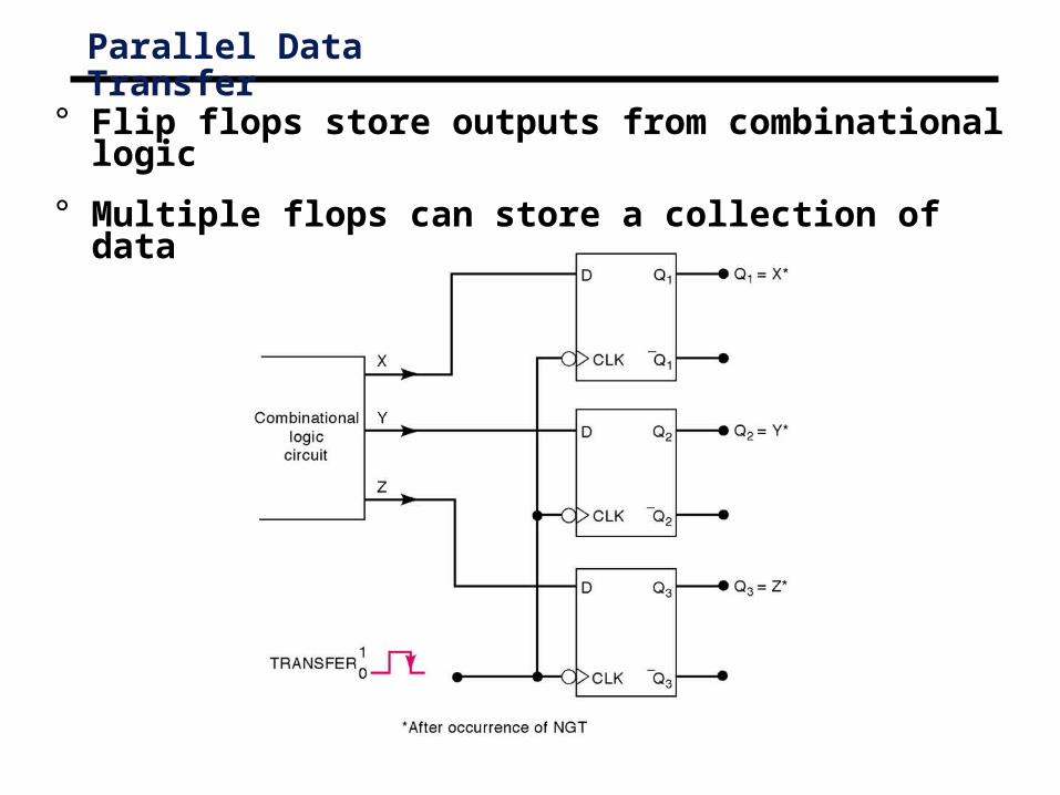
Parallel Data Transfer
° Flip flops store outputs from combinational logic
° Multiple flops can store a collection of data

Summary
° Flip flops are powerful storage elements• They can be constructed from gates and latches!
° D flip flop is simplest and most widely used
° Asynchronous inputs allow for clearing and presetting the flip flop output
° Multiple flops allow for data storage• The basis of computer memory!
° Combine storage and logic to make a computation circuit
° Next time: Analyzing sequential circuits.