CS-030 Pneumatic Flat Press Machine -...
15
www.hh.com.hk e = [email protected] t = 852.24813068 f = 852.24813727 Room 1117, 11/F, Asia Trade Centre, 79 Lei Muk Road, Kwai Chung, N.T., Hong Kong CS-030 Pneumatic Flat Press Machine Operation Manual is powered by H&H Asia Group Limited
-
Upload
nguyennhan -
Category
Documents
-
view
217 -
download
0
Transcript of CS-030 Pneumatic Flat Press Machine -...

www.hh.com.hk
e = [email protected] t = 852.24813068 f = 852.24813727 Room 1117, 11/F, Asia Trade Centre, 79 Lei Muk Road, Kwai Chung, N.T., Hong Kong
CS-030 Pneumatic Flat Press Machine
Operation Manual
is powered by
H&H Asia Group Limited

CS-030 operation manual
issue 1 12.10.29 P.1 of 14
Table of Contents
Precautions with regard to Safety
Name Plate
Introduction
Specifications
Machine Components
Control Panel
Preparation Before Main Power Connected
Machine Operation
Machine Setting
Temperature Controller Adjustment
Press Timer Adjustment
Press Pressure Adjustment
Operation Mode Selection
Trouble Shooting
Appendix A Control Circuit Schematic Diagram

CS-030 operation manual
issue 1 12.10.29 P.2 of 14
> Precautions with regard to Safety
Please observe these safety tips for safe, efficient, an injury-free operation of your equipment. By
strictly following all instruction contained in this manual you will certainly obtain an excellent
performance from the use of this equipment for years.

CS-030 operation manual
issue 1 12.10.29 P.3 of 14
> Precautions with regard to Safety (cont.)

CS-030 operation manual
issue 1 12.10.29 P.4 of 14
> Name Plate

CS-030 operation manual
issue 1 12.10.29 P.5 of 14
> Introduction
Thank you for your choosing of CS-030 which is manufactured by H&H.
The pneumatic flat press machine described in this manual is one of the sophisticated machines for
processing the flat press products in the market today. Built on pure digital control platform and
designed for the professional users. Operators are recommended to have basic knowledge and skill
in heat press operation before using this machine.
This manual is aimed for the operators to understand the machine and avoid damage to the machine
or personnel. Please read this manual carefully and keep it well for daily reference usage.

CS-030 operation manual
issue 1 12.10.29 P.6 of 14
> Specifications
Model : CS-030
Voltage : 220 V, single phase
Frequency : 50/60 Hz
Power Consumption : 3600 W
Compressed Air : >0.4 Mpa
Heat Temperature Range : Room Temperature~300OC
Press Duration : 1~999 second, minute or hour
Heat Press Size : 1000mm X 300mm
Lower Platform Size : 1000mm X 300mm
Overall Dimensions : 1140mm (L) x 860mm (W) x 1820mm (H)
Overall Weight : 208 kg
Note : due to continuous improvement, specifications are subjected to change without prior notification

CS-030 operation manual
issue 1 12.10.29 P.7 of 14
> Machine Components
1. press pressure adjusting knot for the cylinder
2. control panel box
3. protecting cover
4. chassis
5. heating plate & pressing head
6. lower platform
7. machine base
8. safety protective bar
9. air filter and regulator
10. manual control panel
11. start button (work with #12 button together)
12. start button (work with #11 button together)
13. stop button
14. foot pedal
15. foot pedal switches socket
16. power connecting socket
1
2 3
9
6
11 7
14
5
12 13
4
8
15 16 10
CS-030 operation manual
issue 1 12.10.29 P.8 of 14
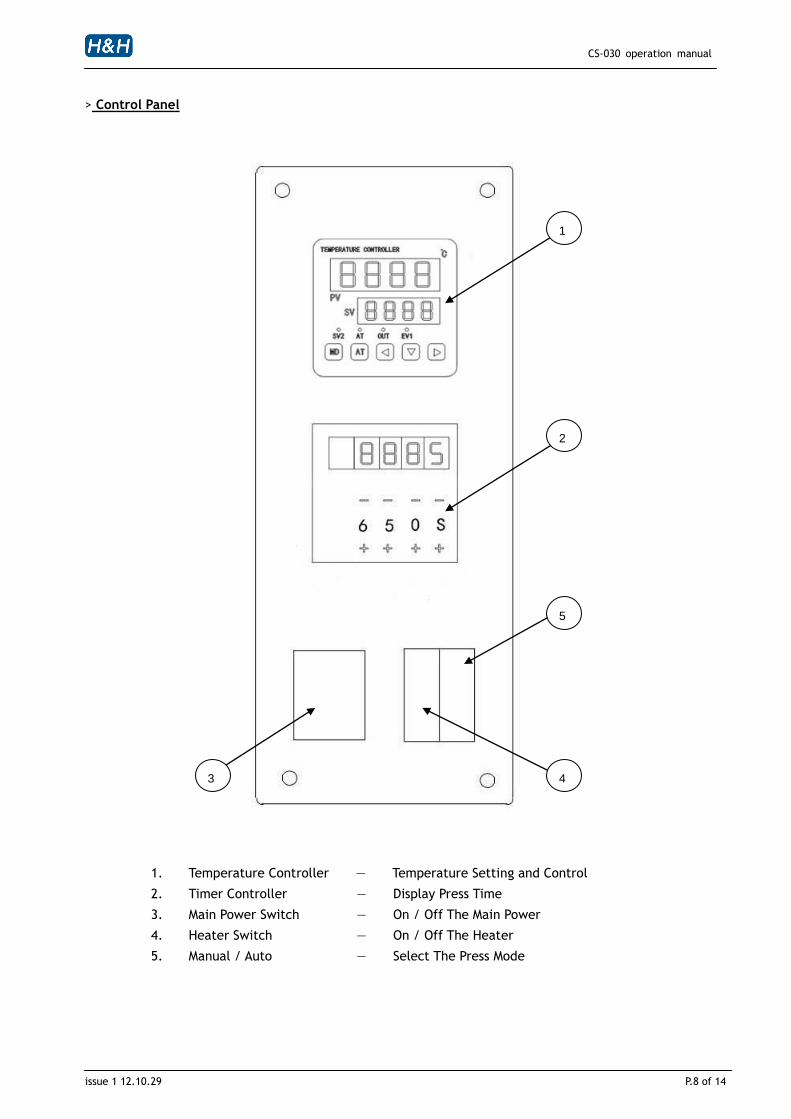
> Control Panel
1. Temperature Controller — Temperature Setting and Control
2. Timer Controller — Display Press Time
3. Main Power Switch — On / Off The Main Power
4. Heater Switch — On / Off The Heater
5. Manual / Auto — Select The Press Mode
1
3
5
2
4

CS-030 operation manual
issue 1 12.10.29 P.9 of 14
> Preparation Before Main Power Connected
1. Compress air connection
Since the heating plate will go up after compress air connected, the cable ties on the heating
plate and the working table should be removed first.
2. Main power connection
The 3-pin main power socket is located at the back of the machine, plug in the main power
connector and tighten the screws
3. Foot switch connection
The 4-pin foot switch socket is located at the back of the machine, plug in the foot switch connect
and tighten the screws.

CS-030 operation manual
issue 1 12.10.29 P.10 of 14
> Machine Operation
1. After connected the main power supply, adjust the heating temperature and time, press pressure,
and select the machine operation mode (manual/auto). Then turn on the heater power, the
temperature of the heating plate will go up gradually.
2. Wait until the heating plate reaches the pre-set temperature. Place the cloth on the working table
and step on the left foot switch once, then the heating plate will go down.
The timer will be triggered simultaneously. After the countdown finished, the heating plate will go
up. The press cycle is completed.
3. If you step on the right foot switch once in the duration of countdown, the timer will be stop
immediately and the heating plate will go up, the press cycle will be terminated.
4. While the machine is working, the heating plate will go up automatically once the safety bar is
triggered.
5. Switch off the main power after the work is finished.
6. You can also using the start & stop button at the manual control panel to control the machine, the
method is basically the same.
.

CS-030 operation manual
issue 1 12.10.29 P.11 of 14
> Machine Setting
>> Temperature Controller Adjustment
Diagram 3
1. PV : Field processing temperature
2. SV : Set target temperature
3. SV2 : Action lamp
4. AT : Auto temp setting lamp
5. AT : Auto temp setting button
6. Position, increase/decrease buttons
7. EV1 output lamp
8. Output lamp
9. MD key : Mode select button
Press the “6a” button (See diagram 3) once or several times for selecting the value input position,
press the up arrow “6b” button and down arrow “6c” button to change the temperature setting and
press the MD key button to finish the temp preset. The preset target temperature will be stored
automatically.
1
2
3
9
5
4
7
8
6a
6b
6c

CS-030 operation manual
issue 1 12.10.29 P.12 of 14
> Machine Setting (Cont.) >> Press Timer Adjustment
The units, hour (H), minute (M) and second (S) can be selected in the timer. Normally, the unit-second (S) is mostly used. The value is set by using the “+” or “_”. For example, the press time 650 seconds, it can be set by using the “+” or “_” below the little squares (See diagram 4).
Diagram 4
>> Press Pressure Adjustment
A. Turn the knob on the compress air filter regulator to adjust the press pressure
B. By adjusting the four adjustment screws below the working table, the pressure of the press
can also be changed, even under the same air pressure setting.
>> Operation Mode Selection
The machine has two operation modes:
A. Manual Mode – Step on the left foot switch, the heating plate goes down. Once move away
the foot, the heating plate goes up.
B. Auto Mode – Step on the right foot switch, the heating plate goes down, after move away the
foot, the timer starts to countdown. When the countdown is completed, the heating plate
goes up.

CS-030 operation manual
issue 1 12.10.29 P.13 of 14
> Trouble Shooting
Problem Cause solution
No power to
individual parts
Fault with power cord or plug Check the power connection
Circuit breaker tripped Reset the breaker and investigate the
system
Main power supply not switch on Switch on the main power supply
Bad contact Check the circuit if there is any loosen
part
Transformer fault Check the voltage of power supply
Temperature monitor
unsteady
Thermocouple fault Replace the temperature sensor
Thermocouple connection is loosen Check and tighten the connection
Temperature controller malfunction Replace the circuit board in the control
box
Thermocouple extension cable short
circuit Check the break point and repair
Thermocouple installed in wrong
position
Check the end point of the sensor and
relocate the position of it
Temperature monitor
showing the ambient
temperature
Heater not started up Press the heat button
Air pressure too low Check the air supply if any leakage point
Thermocouple fault Replace the thermocouple
Power supply voltage unsteady Install voltage stabilizer
Heater temperature
cannot raises up
Solid state relay (SSR) malfunction Replace the SSR
Compressed air pressure too low and
interlocked Increase the compressed air pressure

CS-030 operation manual
issue 1 12.10.29 P.14 of 14
Appendix A . Control Circuit Schematic Diagram
+24V
Timer “NC”
Safety Bar “On / Off”
Right Foot-Switch “On / Off”
Contractor
Contact Point Left Foot-Switch “On / Off”
Manual Auto
Contactor Solenoid
Valve
Timer
-24V