CRYSTALLOGRAPHY IV: PLANES - materials.ucsb.edumatclass/101/pdffiles/Lecture_4.pdfCRYSTALLOGRAPHY...
22
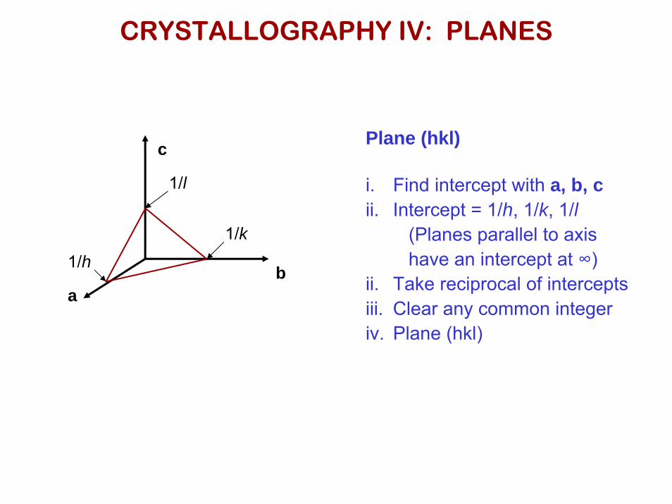
CRYSTALLOGRAPHY IV: PLANES Plane (hkl) i. Find intercept with a, b, c ii. Intercept = 1/h, 1/k, 1/l (Planes parallel to axis have an intercept at ∞) ii. Take reciprocal of intercepts iii. Clear any common integer iv. Plane (hkl) a b c 1/h 1/k 1/l
Transcript of CRYSTALLOGRAPHY IV: PLANES - materials.ucsb.edumatclass/101/pdffiles/Lecture_4.pdfCRYSTALLOGRAPHY...
CRYSTALLOGRAPHY IV: PLANES
Plane (hkl)
i. Find intercept with a, b, cii. Intercept = 1/h, 1/k, 1/l
(Planes parallel to axishave an intercept at ∞)
ii. Take reciprocal of interceptsiii. Clear any common integeriv. Plane (hkl)
ab
c
1/h
1/k
1/l

CRYSTALLOGRAPHY IV: PLANES
(001) (110)
(111)

CRYSTALLOGRAPHY IV: PLANES
Examples
Plane AIntercepts
x: ½y: - ½z: ∞
Plane:
Clear common integerPlane:
( )022
( )011
Instead of writing “-” sign in crystallographic notationWe use a “bar” over the number
( )022 “Two two bar zero”

CRYSTALLOGRAPHY IV: PLANES
Specific plane: (hkl)
Families of planes: {hkl}
( ) ( ) ( ) ( ) ( ) ( )100,001,010,010,001,100{ }100 :

CRYSTALLOGRAPHY V: HEXAGONALHexagonal:
|a| = a|b| = a|c| = c
α = β = 90°γ = 120°
Two crystallographic conventions: three-index and four-index
[ ] [ ]
( )
( )
')(
''23
''23
'''
nwwvut
uvnv
vunu
uvtwwvu
=+−=
−=
−=
→
( ) ( ))( khi
hkilhkl+−=
→

CRYSTALLOGRAPHY: Close-Packed Planes
FCC Metals: (111) HCP Metals: (0001)
FCC Stacking
…ABCABCABC…
HCP Stacking
…ABABABABAB…

CRYSTALLOGRAPHY: Close-Packed Planes
FCC Stacking (111)…ABCABCABC…
HCP Stacking (0001)…ABABABABAB…

POLYCRYSTALLINE MATERIALS: EXAMPLE
Grain formation in solidification
Squares:Represent unit cells
Individual crystals or “grains”
Grain boundaries
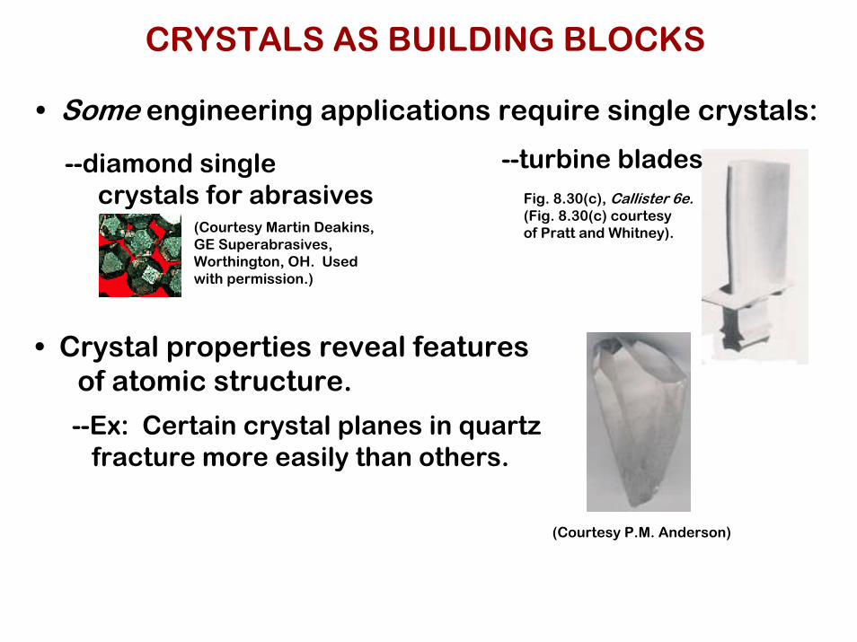
CRYSTALS AS BUILDING BLOCKS
• Some engineering applications require single crystals:
• Crystal properties reveal featuresof atomic structure.
--Ex: Certain crystal planes in quartzfracture more easily than others.
--diamond singlecrystals for abrasives
--turbine bladesFig. 8.30(c), Callister 6e.(Fig. 8.30(c) courtesyof Pratt and Whitney).(Courtesy Martin Deakins,
GE Superabrasives, Worthington, OH. Used with permission.)
(Courtesy P.M. Anderson)

POLYCRYSTALS
• Most engineering materials are polycrystals.
Adapted from Fig. K, color inset pages of Callister 6e.(Fig. K is courtesy of Paul E. Danielson, Teledyne Wah Chang Albany)
1 mm
• Nb-Hf-W plate with an electron beam weld.• Each "grain" is a single crystal.• If crystals are randomly oriented,
overall component properties are not directional.• Crystal sizes typ. range from 1 nm to 2 cm
(i.e., from a few to millions of atomic layers).
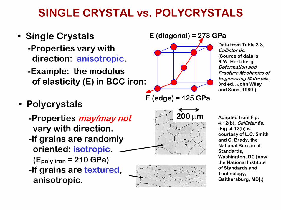
SINGLE CRYSTAL vs. POLYCRYSTALS
• Single Crystals-Properties vary with
direction: anisotropic.
-Example: the modulusof elasticity (E) in BCC iron:
• Polycrystals
-Properties may/may notvary with direction.
-If grains are randomlyoriented: isotropic.(Epoly iron = 210 GPa)
-If grains are textured,anisotropic.
E (diagonal) = 273 GPa
E (edge) = 125 GPa
200 µm
Data from Table 3.3, Callister 6e.(Source of data is R.W. Hertzberg, Deformation and Fracture Mechanics of Engineering Materials, 3rd ed., John Wiley and Sons, 1989.)
Adapted from Fig. 4.12(b), Callister 6e.(Fig. 4.12(b) is courtesy of L.C. Smith and C. Brady, the National Bureau of Standards, Washington, DC [now the National Institute of Standards and Technology, Gaithersburg, MD].)

DEMO: HEATING andCOOLING of an IRON WIRE
• Fe demonstrates "polymorphism" The same atoms can have more than one crystal structure.
Temperature, C
BCC Stable
FCC Stable
914
1391
1536
shorter
longer!shorter!
longer
Tc 768 magnet falls off
BCC Stable
Liquid
heat up
cool down

SUMMARY
• Atoms may assemble into crystalline oramorphous structures.
• We can predict the density of a material,provided we know the atomic weight, atomicradius, and crystal geometry (e.g., FCC,BCC, HCP).
• Material properties generally vary with singlecrystal orientation (i.e., they are anisotropic),but properties are generally non-directional(i.e., they are isotropic) in polycrystals withrandomly oriented grains.

CHAPTER 12: STRUCTURE AND PROPERTIES OF CERAMICS
ISSUES TO ADDRESS...
• Structures of ceramic materials:How do they differ from that of metals?
• Point defects:How are they different from those in metals?
• Impurities:How are they accommodated in the lattice and howdo they affect properties?
• Mechanical Properties:What special provisions/tests are made for ceramicmaterials?

CERAMIC BONDING
• Bonding:--Mostly ionic, some covalent.--% ionic character increases with difference in
electronegativity.
He -
Ne -
Ar -
Kr -
Xe -
Rn -
Cl 3.0
Br 2.8
I 2.5
At 2.2
Li 1.0
Na 0.9
K 0.8
Rb 0.8
Cs 0.7
Fr 0.7
H 2.1
Be 1.5
Mg 1.2
Sr 1.0
Ba 0.9
Ra 0.9
Ti 1.5
Cr 1.6
Fe 1.8
Ni 1.8
Zn 1.8
As 2.0
C 2.5Si
1.8
F 4.0
Ca 1.0
Table of Electronegativities
CaF2: large
SiC: small
Adapted from Fig. 2.7, Callister 6e. (Fig. 2.7 is adapted from Linus Pauling, The Nature of the Chemical Bond, 3rd edition, Copyright 1939 and 1940, 3rd edition. Copyright 1960 byCornell University.
• Large vs small ionic bond character:

IONIC BONDING and STRUCTURE
• Charge Neutrality:--Net charge in the
structure shouldbe zero.
--General form: AmXp
m, p determined by charge neutrality• Stable structures:
--maximize the # of nearest oppositely charged neighbors.
Adapted from Fig. 12.1, Callister 6e.
- -
- -+
unstable
- -
- -+
stable
- -
- -+
stable
CaF2: Ca2+cation
F-
F-
anions+

COORDINATION # and IONIC RADII
• Coordination # increases withIssue: How many anions can you
arrange around a cation?
rcationranion
rcationranion
Coord #
< .155 .155-.225 .225-.414 .414-.732 .732-1.0
ZnS (zincblende)
NaCl (sodium chloride)
CsCl (cesium
chloride)
2 3 4 6 8
Adapted from Table 12.2, Callister 6e.
Adapted from Fig. 12.2, Callister 6e.
Adapted from Fig. 12.3, Callister 6e.
Adapted from Fig. 12.4, Callister 6e.
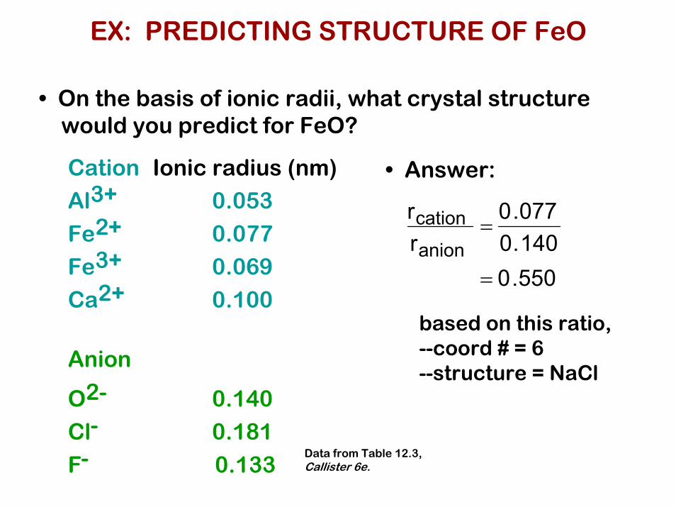
EX: PREDICTING STRUCTURE OF FeO
• On the basis of ionic radii, what crystal structurewould you predict for FeO?
Cation
Al3+
Fe2+
Fe3+
Ca2+ Anion
O2-
Cl-
F-
Ionic radius (nm)
0.053
0.077
0.069
0.100
0.140
0.181
0.133
• Answer:
rcationranion
=0.0770.140
= 0.550
based on this ratio,--coord # = 6--structure = NaCl
Data from Table 12.3, Callister 6e.

AmXp STRUCTURES
• Consider CaF2 :
rcationranion
=0.1000.133
≈ 0.8
• Based on this ratio, coord # = 8 and structure = CsCl.
• Result: CsCl structure w/only half the cation sitesoccupied.
• Only half the cation sitesare occupied since#Ca2+ ions = 1/2 # F- ions.
Adapted from Fig. 12.5, Callister 6e.

DEFECTS IN CERAMIC STRUCTURES
• Frenkel Defect--a cation is out of place.
• Shottky Defect--a paired set of cation and anion vacancies.
Shottky Defect:
Frenkel Defect
• Equilibrium concentration of defects ~ e−QD /kT
Adapted from Fig. 13.20, Callister 5e. (Fig. 13.20 is from W.G. Moffatt, G.W. Pearsall, and J. Wulff, The Structure and Properties of Materials, Vol. 1, Structure, John Wiley and Sons, Inc., p. 78.) See Fig. 12.21, Callister 6e.

IMPURITIES
• Impurities must also satisfy charge balance
• Ex: NaCl Na+ Cl-
• Substitutional cation impurity
initial geometry Ca2+ impurity resulting geometry
Ca2+
Na+
Na+Ca2+
cation vacancy
• Substitutional anion impurity
initial geometry O2- impurity
O2-
Cl-
anion vacancy
Cl-
resulting geometry
SUMMARY
• Ceramic materials have mostly covalent & some ionic bonding.
• Structures are based on:--charge neutrality--maximizing # of nearest oppositely charged neighbors.
• Structures may be predicted based on:--ratio of the cation and anion radii.
• Defects--must preserve charge neutrality--have a concentration that varies exponentially w/T.