Crystallization -...
23
Crystallization Stephen M. Glasgow 1.0 INTRODUCTION Crystallization is one of the oldest methods known for recovering pure solids from a solution. The Chinese, for example, were using crystallization to recover common salt from water some 5000 years ago. The perfection and beauty of the crystal which fascinated the early tribes now leads to a product of high purity and attractive appearance. By producing crystals of a uniform size, a product which has good flow, handling, packaging, and storage characteristics is obtained. Crystallization is still often thought of as an art rather than a science. While some of the aspects of art are required for control of an operating crystallizer, the discoveryby Miers of the metastable region of the supersatu- rated state has made it possibleto approachthe growth ofcrystals to aunifonn size in a scientific manner. To produce pure crystalline solids in an efficient manner, the designer of crystallization equipment takes steps to ensure the control of 1. The formation of a supersaturated solution 2. The appearance of crystal nuclei 3. The growth of the nuclei to the desired size 535
Transcript of Crystallization -...
Crystallization
Stephen M. Glasgow
1.0 INTRODUCTION
Crystallization is one of the oldest methods known for recovering pure solids from a solution. The Chinese, for example, were using crystallization to recover common salt from water some 5000 years ago.
The perfection and beauty of the crystal which fascinated the early tribes now leads to a product of high purity and attractive appearance. By producing crystals of a uniform size, a product which has good flow, handling, packaging, and storage characteristics is obtained.
Crystallization is still often thought of as an art rather than a science. While some of the aspects of art are required for control of an operating crystallizer, the discovery by Miers of the metastable region of the supersatu- rated state has made it possible to approach the growth ofcrystals to aunifonn size in a scientific manner.
To produce pure crystalline solids in an efficient manner, the designer of crystallization equipment takes steps to ensure the control of
1. The formation of a supersaturated solution 2. The appearance of crystal nuclei 3. The growth of the nuclei to the desired size
535
536 Fermentation and Biochemical Engineering Handbook
2.0 THEORY
The first consideration of the equipment designer is the control of the formation of a saturated solution. In order to do this, it is necessary to understand the field of supersaturation.
2.1 Field of Supersaturation
The solubility chart divides the field of the solution into two regions: the subsaturated region where the solution will dissolve more of the solute at the existing conditions, and the supersaturated region.
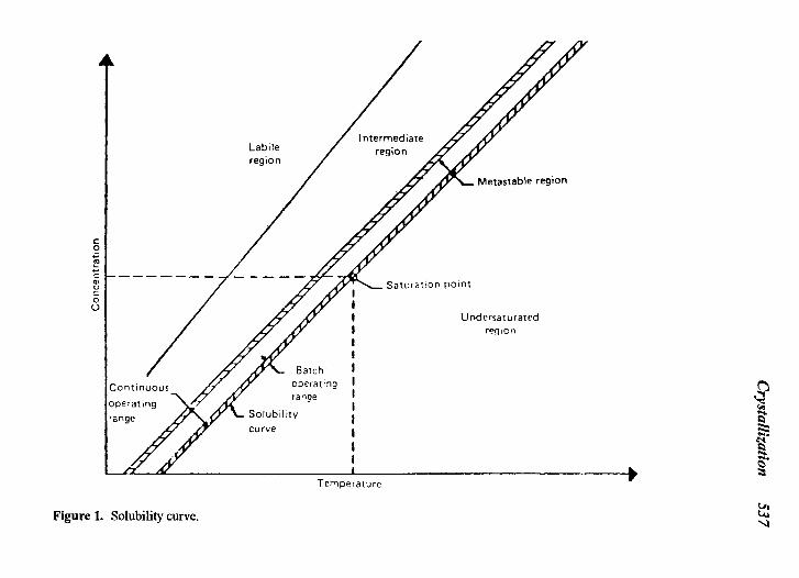
Before Miers identified the metastable field, it was thought that a solution with a concentration of solute greater than the equilibrium amount would immediately form nuclei. Miers’ research and the findings of subsequent researchers determined that the field of supersaturation actually consists of at least three loosely identified regions (Fig. 1):
Metastable region-where solute in excess of the equilib- rium concentration will deposit on existing crystals, but no new nuclei are formed. Intermediate region-where solute in excess of the equilib- rium concentration will deposit on existing crystals and new nuclei are formed. Labile region-where nuclei are formed spontaneously from a clear solution.
The equipment designer wishes to control the degree of supersaturation of the solution in the metastable region when designing a batch crystallizer. In this region, where growth takes place only on existing crystals, all crystals have the same growth time and a very uniform crystal size is obtained.
When designing a continuous crystallizer, the designer wishes to control the degree of supersaturation in the lower limits of the intermediate region. In continuous crystallization, it is necessary to replace each crystal removed from the process with a new nuclei. It is also necessary to provide some degree of crystal size classification if a uniform crystal size is to be obtained.
Solutions of most organic chemicals can, as a general rule, attain a considerably higher degree of supersaturation than inorganic chemicals. The formation of crystalline nuclei requires a definite orientation ofthe molecules
Crystallization
53 7
538 Fermentation and Biochemical Engineering Handbook
in the solution. This requires the proper orientation of several molecules at the moment of a random collision. Since the number of possible orientations increases with increasing complexity of the molecule, considerably higher degrees of supersaturation can be obtained for solutions of chemicals with complex molecules.
2.2 Formation of a Supersaturated Solution
If a solution is to have only a slight degree of supersaturation, then a cyclic system in which large quantities of liquor are supersaturated uniformly is required. The solution must then be brought back to saturation before feed liquor is allowed to enter the system and the mixture is again supersaturated in the next cycle.
The removal of the metastable supersaturation is a slow process. A large amount of crystal surface is required to allow for the large number of random collisions necessary to remove the supersaturation generated during the cycle. The proper orientation of both the molecules in solution and the molecule on the crystal surface is required for deposition, and the increased complexity of the molecule increases the number of collisions required for proper orientation.
If the supersaturation generated during the cycle is not completely removed, the level of supersaturation attained during the following cycle is increased. This increase from cycle to cycle will continue until the supersatu- ration level ofthe solution exceeds the metastable region and enters the labile region, where spontaneous nucleation occurs. The occurrence of spontane- ous nucleation means loss of control of crystal size.
Supersaturation is clearly the most important single consideration for any crystallization process. By giving proper attention to the degree of supersaturation generated during each cycle and its proper release during the design stage, half the battle will be won. Supersaturation should be controlled by making certain only small changes in temperature and composition occur in the mass of mother liquor.
2.3 Appearance of Crystalline Nuclei
Usually the crystallization equipment is charged with a clear feed solution. As this solution is saturated, it is important to control the increase in supersaturation as the labile region is approached. This is important since the formation of an excessive number of nuclei will cause a continuous crystallizer system to have an extremely long period before desired crystal
Crystallization 539
size can be achieved and prevent a batch system from ever producing desired crystal size during that particular run.
Once initial nucleation has been achieved successfully, the control of secondary nucleation becomes important. Since crystal growth is a surface phenomenon, each nuclei formed is available to absorb the supersaturation generated by the cycle. This means that only one nuclei is to be formed for each single crystal removed if a constant crystal size is to be maintained.
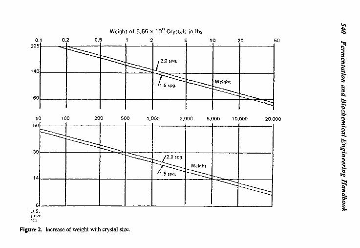
When an excessive number of nuclei are formed during operation ofthe crystallizer, the average size of the final product is reduced. As an example of this effect, one can assume the formation of 1 lb. of 200 mesh nuclei. Assuming that no further new nuclei are formed, this 1 lb would weigh 8 lbs. if grown to 100 mesh crystals. Following this trend further, it is found that growth to 60 mesh crystals will result in 38 lbs; 14 mesh crystals would yield 7000 lbs (see Fig. 2).
Secondary nucleation is constantly occurring. It occurs when a crystal collides with the vessel wall or with another crystal. To control this collision- induced nucleation the number of crystals in the system must be controlled.
Increasing the local supersaturation into the labile region will also cause secondary nucleation. This occurs when there are local cold spots caused by radiation from the vessel wall, subcooling caused by subsurface boiling and build up of residual supersaturation in solutions with high viscosity and insufficient agitation. This calls attention to the need for insulation ofthe vessel, for control to ensure that boiling occurs at the liquid- vapor interface, and for provision for sufficient agitation ofthe solution in the vessel.
Mechanically induced nucleation can result from excessive agitation caused by an impeller sweeping through a solution in the metastable region of supersaturation or turbulence caused by violent boiling. By limiting the tip speed of a pump or agitator and limiting the escape velocity at the vapor- liquid interface, this type of secondary nucleation can be minimized.
After the control of supersaturation, control of nuclei formation is the most important consideration in the design of crystallization equipment. If a constant number of crystals are maintained in the crystallizer, then a constant surface area for crystal growth will be available. This will result in good control of product size.
2.4 Growth of Nuclei to Size
As noted above, crystal growth is a surface phenomenon. Given sufficient agitation, the depositing of solute on the surface is controlled by
540 F
ermentation and B
iochemical E
ngineering Handbook
0 0
0.
N t
I/ I
Crystallization 541
proper orientation of the molecules, rather than by film diffusion to the surface; the crystal growth rate approaches zero order with increasing driving force. Since growth becomes a function of time only, the crystal must be retained in the crystallizer for a sufficient amount oftime to allow it togrow to the desired size.
The growth type crystallizers maintain the crystals in a fluidized bed (thereby providing both agitation and size classification of the crystals). The supersaturated solution flows through the fluidized bed and releases the supersaturation to the crystal surface.
Not all crystals will remain in the crystallizer the calculated retention time. This is only a statistical average. Since there will be a range of growth times, there will be a distribution of crystal sizes. The more narrow the range of actual retention times, the more narrow the crystal size distribution.
3.0 CRYSTALLIZATION EQUIPMENT
The type of equipment to be used in a crystallization process depends primarily upon the solubility characteristic of the solute. Solutions from fermentation processes can be classified as follows:
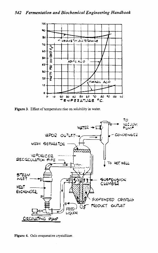
1. Chemicals where a change in solution temperature has little effect on the solubility. An example is hexamethyl- enetetramine as shown in Fig. 3 . The supersaturated solution is produced by evaporation of the solvent. The equipment needed here is called an evaporative crystal- lizer (see Fig. 4).
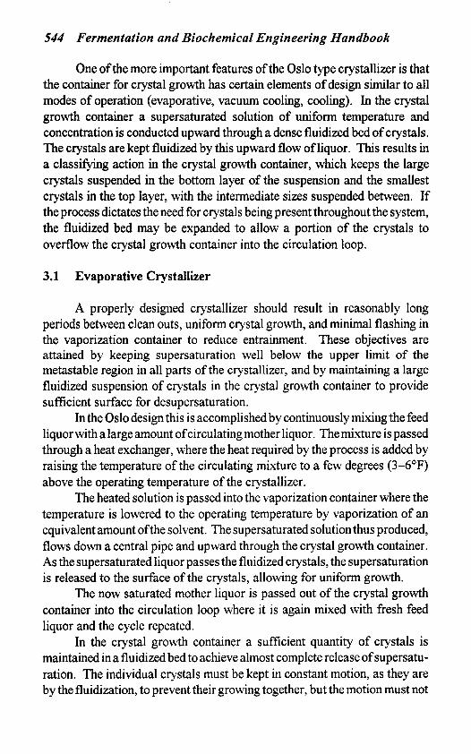
2. Chemicals, e.g., fumaric acid, which show only a moder- ate increase in solubility with increasing temperature. A combination of evaporation and cooling may be used to produce the supersaturated solution. Depending upon the yield required, this operation may be carried out in either a vacuum cooling crystallizer or an evaporative crystal- lizer (see Fig. 5) .
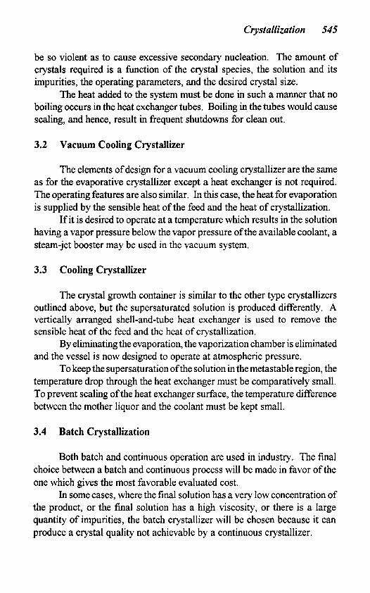
3. Chemicals, e.g., adipic acid, which show a large increase in solubility with increasing temperature. Cooling the solution can be an effective way to produce the supersatu- rated solution, although a combination of evaporation and cooling can also be employed. In addition to the two types of crystallizers mentioned above, a cooling crystallizer may be used (see Fig. 6).
542 Fermentation and Biochemical Engineering Handbook
Figure 3. Effect of temperature rise on solubility in water.
PEC
cteWunnrG w
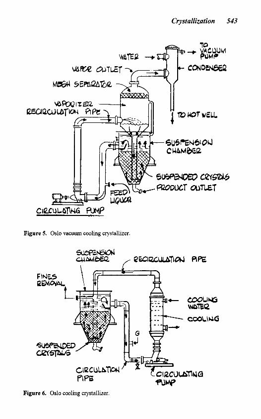
Figure 4. Oslo evaporative crystallizer.
Crystallization 543
Figure 5. Oslo vacuum cooling crystallizer.
- e o o u a
Figure 6. Oslo cooling crystalllzer
544 Fermentation and Biochemical Engineering Handbook
One of the more important features of the Oslo type crystallizer is that the container for crystal growth has certain elements of design similar to all modes of operation (evaporative, vacuum cooling, cooling). In the crystal growth container a supersaturated solution of uniform temperature and concentration is conducted upward through a dense fluidized bed of crystals. The crystals are kept fluidized by this upward flow of liquor. This results in a classifjrlng action in the crystal growth container, which keeps the large crystals suspended in the bottom layer of the suspension and the smallest crystals in the top layer, with the intermediate sizes suspended between. If the process dictates the need for crystals being present throughout the system, the fluidized bed may be expanded to allow a portion of the crystals to overflow the crystal growth container into the circulation loop.
3.1 Evaporative Crystallizer
A properly designed crystallizer should result in reasonably long periods between clean outs, uniform crystal growth, and minimal flashing in the vaporization container to reduce entrainment. These objectives are attained by keeping supersaturation well below the upper limit of the metastable region in all parts of the crystallizer, and by maintaining a large fluidized suspension of crystals in the crystal growth container to provide sufficient surface for desupersaturation.
In the Oslo design this is accomplished by continuously mixing the feed liquor with a large amount ofcirculatingmother liquor. The mixture is passed through a heat exchanger, where the heat required by the process is added by raising the temperature of the circulating mixture to a few degrees (3-6'F) above the operating temperature of the crystallizer.
The heated solution is passed into the vaporization container where the temperature is lowered to the operating temperature by vaporization of an equivalent amount ofthe solvent. The supersaturated solution thus produced, flows down a central pipe and upward through the crystal growth container. As the supersaturated liquor passes the fluidized crystals, the supersaturation is released to the surface of the crystals, allowing for uniform growth.
The now saturated mother liquor is passed out of the crystal growth container into the circulation loop where it is again mixed with fresh feed liquor and the cycle repeated.
In the crystal growth container a sufficient quantity of crystals is maintained in a fluidized bed to achieve almost complete release of supersatu- ration. The individual crystals must be kept in constant motion, as they are by the fluidization, to prevent their growing together, but the motion must not
Crystallization 545
be so violent as to cause excessive secondary nucleation. The amount of crystals required is a function of the crystal species, the solution and its impurities, the operating parameters, and the desired crystal size.
The heat added to the system must be done in such a manner that no boiling occurs in the heat exchanger tubes. Boiling in the tubes would cause scaling, and hence, result in frequent shutdowns for clean out.
3.2 Vacuum Cooling Crystallizer
The elements of design for a vacuum cooling crystallizer are the same as for the evaporative crystallizer except a heat exchanger is not required. The operating features are also similar. In this case, the heat for evaporation is supplied by the sensible heat of the feed and the heat of crystallization.
If it is desired to operate at a temperature which results in the solution having a vapor pressure below the vapor pressure of the available coolant, a steam-jet booster may be used in the vacuum system.
3.3 Cooling Crystallizer
The crystal growth container is similar to the other type crystallizers outlined above, but the supersaturated solution is produced differently. A vertically arranged shell-and-tube heat exchanger is used to remove the sensible heat of the feed and the heat of crystallization.
By eliminatingthe evaporation, the vaporization chamber is eliminated and the vessel is now designed to operate at atmospheric pressure.
To keep the supersaturation ofthe solution in themetastable region, the temperature drop through the heat exchanger must be comparatively small. To prevent scaling of the heat exchanger surface, the temperature difference between the mother liquor and the coolant must be kept small.
3.4 Batch Crystallization
Both batch and continuous operation are used in industry. The final choice between a batch and continuous process will be made in favor of the one which gives the most favorable evaluated cost.
In some cases, where the final solution has a very low concentration of the product, or the final solution has a high viscosity, or there is a large quantity of impurities, the batch crystallizer will be chosen because it can produce a crystal quality not achievable by a continuous crystallizer.
546 Fermentation and Biochemical Engineering Handbook
The basic design criteria used for a continuous crystallizer also apply to a batch crystallizer. These criteria are to:
1. Maintain the solution in the metastable region of super-
2. Provide a large fluidized bed of crystal to allow effective,
3, Minimize secondary nucleation
saturation
efficient release of supersaturation
The batch crystallizer is filled with hot feed solution and then cooled, either by evaporation of solvent by lowering of the operating pressure (vacuum cooling) or by using a heat exchanger and a coolant fluid. As the feed is cooled, a supersaturated solution is produced. From this supersatu- rated solution, the crystalline nuclei are formed. The crystals are grown to their final size as further cooling continues to produce supersaturation as the driving force. At the end of the batch cycle, the magma is removed from the crystallizer and sent to the dewatering equipment to recover the crystals.
4.0 DATA NEEDED FOR DESIGN
The first and most important piece of information required is a solubility curve. If solubility data for the specific solution is not available, information which is at least representative must be supplied.
The next set of information required is the physical properties of the solutions. These are viscosity, specific heat, specific gravity, boiling point elevation and thermal conductivity. While all these datamay not be available, those available will give the experienced designer the information required to make an intelligent “guess-timate” of the missing physical property values.
The third set of data includes those variables set by the plant. These are quality and quantity of utilities available; composition, temperature, and quantity offeed solution; and finally, desired production rate and quality (size distribution) of final product.
The final data the designer hopes for are pilot plant data from tests he has conducted. It is here that the designer determines what level of supersaturation the solution can support, the crystal surface area required for desupersaturation, the effect of secondary nucleation, and the residence time required for growth to desired size. Some of these values are measured directly while others are implied by indirect measurements.
Although the major suppliers of crystallization equipment have exten- sive experience in crystallization and can often design equipment which will
Crystallization 547
operate satisfactorily fromthe solubility curve and the values for the physical properties, it is still advisable to conduct pilot plant studies on typical solutions from an operating commercial plant or process pilot plant. The presence of impurities, pH of the solution, and solubility of the product at the operating temperature all have an effect on crystal growth rate, shape and purity. By running commercial solutions in a pilot plant, the designer can detect problems which may arise during the crystallization process and possible overall process problems may be anticipated.
Due to the importance of pilot plant test data, all of the major crystallization equipment suppliers maintain a wellsquipped pilot plant and have an experienced and knowledgeable staff. These operators, engineers, and designers have defined the parameters for scaleup very well, so well that scaleups of over 2,000 to 1 have been made successfdly.
5.0 SPECIAL CONSIDERATIONS FOR FERMENTATION PROCESSES
The preceding sections dealt with the design considerations for crystal- lization in general terms. Now emphasis is directed to areas of special concern for the processing of organic chemicals.
5.1 Temperature Limitation
Because the properties of an organic chemical can be altered by prolonged exposure to high temperature, an upper temperature limit of 70°C is set for solutions produced by fermentation processes. The value can be raised or lowered if test work so indicates.
5.2 High Viscosity
Most aqueous solutions of high molecular weight organic chemicals have a high viscosity. Since the upper temperature of the solution is limited, this problem cannot be overcome by raising the operating temperature. The high viscosity dampens the turbulence of the solution in the fluidized bed, making effective and efficient contact of the crystals and the supersaturated solution very difficult. Inefficient contact leads to a buildup in residual supersaturation and hence, excessive nucleation. Often equipment to remove fine (very small crystals) must be supplied as part of a crystallization system for aqueous solutions of organic compounds.
548 Fermentation and Biochemical Engineering Handbook
5.3 Long Desupersaturation Time
Due to the nature of long chain organic molecules, deposition on the crystal surface is more difficult and time consuming than for most inorganic chemicals. This must betaken into consideration and additional time allowed between cycles so that the supersaturation can be relieved. Another effective method for handling this potential problem is to limit the supersaturation generated during each cycle.
5.4 Slow Crystal Growth Rate
The problem of deposition is compounded by an increased film resistance, due to high viscosity and to the long chains of the molecules. The result is a decrease in the average growth rate; however, solutions of organic compounds can, as ageneral rule, support ahigher supersaturation than those of inorganic chemicals. This allows the designer to use a higher driving force, but usually, a longer retention time is also required.
6.0 METHOD OF CALCULATION
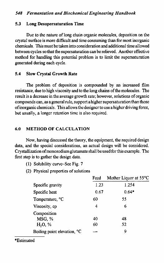
Now, having discussed the theory, the equipment, the required design data, and the special considerations, an actual design will be considered. Crystallization ofmonosodiumglutamate shall be used for this example. The first step is to gather the design data.
(1) Solubility curve-See Fig. 7 (2) Physical properties of solutions
Feed Mother Liquor at 55°C Specific gravity 1.23 1.254 Specific heat 0.67 0.64* Temperature, "C 60 5 5 Viscosity, cp 4 6 Composition MSG, % 40 48 H,O, % 60 52
Boiling point elevation, "C - 9
*Estimated
Crystallization 549
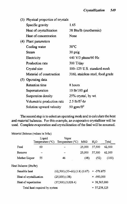
(3) Physical properties of crystals Specific gravity Heat of crystallization Heat of concentration
(4) Plant parameters Cooling water steam Electricity Production rate Crystal size Material of construction
(5) Operating data Retention time Supersaturation Suspension density Volumetric production rate Solution upward velocity
1.65 38 Btu/lb (exothermic) None
38OC 30 psig 440 V/3 phase160 Hz 300 T/day 100-125 U.S. standard mesh 3 16L stainless steel, food grade
8 hours 10 lb/ 100 gal 25% crystal, by wt.
2.5 lb/ft3-hr 50 gpdft2
The second step is to select an operating mode and to calculate the heat and material balances. For this example, an evaporative crystallizer will be used. Complete evaporation and crystallization of the feed will be assumed.
Material Balance (values in I b h ) Liquid Vapor
Temperature ("C) Temperature ("C) MSG H,O Total
Feed 60 - 25,000 37,500 62,500
Remove - - 25,000 37,500 62,500
Mother Liquor 55 46 (48) (52) (100)
Heat Balance (Btu/hr)
Sensible heat (62,500) (5540) (1.8) (0.67) = -376.875
Heat of crystallization (25,000) (-38) = -950,000
Heat of vaporization (37,500) (1,028.4) = 38,565,000
= 37,238,125 Total heat required by system
550 Fermentation and Biochemical Engineering Handbook
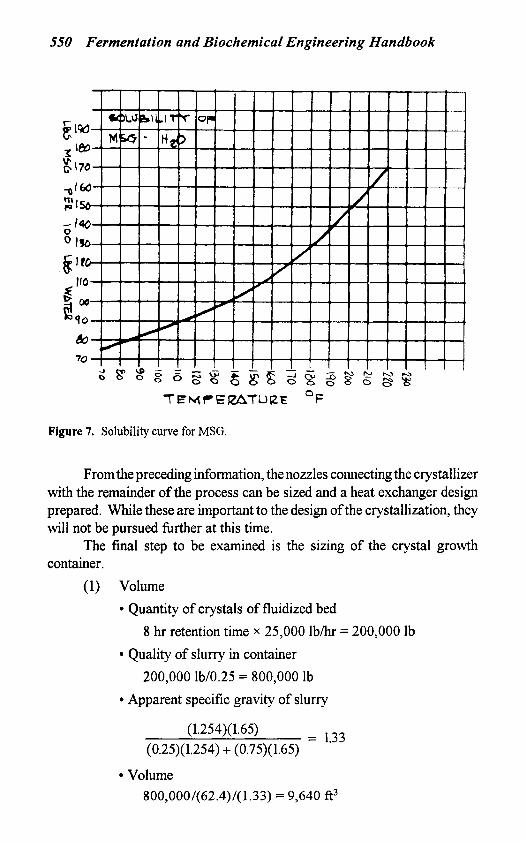
Figure 7. Solubility curve for MSG.
Fromthe preceding information, the nozzles connecting the crystallizer with the remainder of the process can be sized and a heat exchanger design prepared. While these are important to the design of the crystallization, they will not be pursued further at this time.
The final step to be examined is the sizing of the crystal growth container.
(1) Volume Quantity of crystals of fluidized bed
Quality of slurry in container 200,000 lb/0.25 = 800,000 Ib
Apparent specific gravity of slurry
(1.254)(1.65) (0.25)(1.254) + (0.75)( 1.65)
800,000/(62.4)/(1.33) = 9,640 ft3
8 hr retention time x 25,000 I b h = 200,000 Ib
= 1.33
Volume
Crystallization 551
Check-volumetric production rate 25,000/9,640 = 2.59 Ib/hr-ft3 Target value 2.5 Ib/hr-ft3 This is acceptable
(2) Diameter Circulation rate
25y0001b/hr X x 1,000=42,000gpm (60 min / hr) (1 0 Ib)
Cross-sectional area 42,000 g p d 5 0 gpdft2 = 840 ft2
Diameter-use 33'-0" (855.3 ft2)
Head volume-4,000 ft3 Volume of cylinder-5,640 ft3 Straight side
5,640 ft3/855.3 A* = 6.6 ft
(3) Vessel straight side
7.0 TROUBLESHOOTING
At some point during operation of a crystallizer, difficulties are going to occur. A list of some of the more common difficulties along with probable causes and recommended remedies is given below.
7.1 Deposits
1. Local cooling due to lack of insulation. This causes an increase in local supersaturation into the labile region. To remedy, insulate all areas of the crystallizer and piping carrying saturated liquors, particularly protruding points such as reinforcing rings.
2. Low suspension density. Since the solution cannot return to saturation before being resupersaturated in the circu- lation loop, the residual supersaturation builds up to the point that the solution is in the labile region. To remedy, increase the crystals in suspension to maintain the design density.
552 Fermentation and Biochemical Engineering Handbook
3. Protruding gaskets, rough areas on process surface. These areas provide a place for crystal nucleation and growth. Since the object is to grow the crystals in the solution, not on the vessel walls, it is necessary to remove protrusions and polish the rough areas.
7.2 Crystal Size Too Small
1. Low suspension density. This decreases average reten- tion time, hence, the amount of time for crystal growth is insufficient. To correct, increase crystals in suspension to maintain design density.
2. High circulation rate. This causes the fluidized crystal bed to become overextended resulting in too many void areas. This will result in improper release of supersatu- ration. To correct, maintain the circulation rate at the design rate.
3. Solids in feed. Th i s introduces nuclei into the crystallizer in excess of the number required for size control. To correct, make sure the feed solution is free of solids, especially crystals.
4. Design feed rate exceeded. At design suspension density, this results in a reduced average retention time. Within limits, this can be corrected by increasing the suspension density. An increase in production rate usually requires an increase in circulation rate to handle the additional supersaturation and the heavier fluidized bed of crystal
5 . Excessive nucleation. In addition to points 1 to 3 above, this is caused by excessive turbulence, local cold spots and subsurface boiling. To correct, maintain level at design point and maintain pump or agitator speed at design point.
6 . In some cases it is very difficult to prevent excess nucle- ation. Excess nucleation results in high surface area to weight ratio, which prevents proper growth. In some cases it becomes necessary to remove fine salt (nuclei) from the system by dissolving or settling. A portion of liquor which contains fine salt is pumped from the crystal- lizer to a settler or heat exchanger where either all or a portion of the fine salt is removed. This is referred to as afines removal system.
Crystallization 553
7.3 Insufficient Vacuum
1. Obstruction in vapor system. This causes excessive pressure drop. The obstruction is usually a deposit in the noncondensible take off nozzle of the condenser. The obstruction must be removed to correct the problem.
2 . Insuficient cooling water or cooling water above design temperature. This results in overloading the vacuum system because of insufficient subcooling of the noncondensible gases resulting in excess water of satura- tion in the noncondensible stream. Cooling water at the design flow rate and at or below the design temperature must be provided to correct the problem.
3 . Air leaks in system. This results in overloading the vacuum system because of excess noncondensibles and water ofsaturation in noncondensible stream. Air leakage must be stopped to correct the problem.
This is caused by an obstruction in the noncondensible discharge pipe or the discharge pipe sealed too deeply in the hot well. The obstruction must be removed or the depth of the seal in the hot well reduced to correct the problem.
5 . Flooded intercondenser. This is usually caused by a blockage in the discharge line or by using an excess amount of cooling water. The flooded condenser causes excessive pressure drop in the vacuum system. To correct, remove blockage or reduce cooling water flow to design rate.
6. Low steampressure. This applies to steam ejectors only. The cause is low line pressure, wet steam or blockage in the steam line. This reduces thedriving force ofthe ejector and reduces its air handling capacity. By removing the cause of the low steam pressure, the problem of insufi- cient vacuum is corrected.
7. Low seal waferflow. This applies to mechanical vacuum pumps only. This reduces the subcooling of the noncondensible, increasing the loading to the system.
4. Excessive backpressure on vacuum system.
554 Fermentation and Biochemical Engineering Handbook
Seal water must be maintained at design flow to correct the problem.
8 . Low rpm for vacuum pump. This usually is caused by V- belt slippage or low voltage to the motor. To correct, tighten V-belts or reduce load on electric circuit to motor.
7.4 Instrument Malfunction
1 . Air leaks. This causes erroneous reading at the instru- ment. To remedy, seal air leak.
2. Pluggedpurge line. If low pressure purge line is plugged, the instrument will givethe minimum reading; conversely, if the high pressure side is plugged, the maximum reading will be indicated. To prevent purge lines from plugging, they should be given a good flushing at least twice a shift.
3 . Purge liquor boiling in purge line. This occurs when vapor pressure of purge liquor is higher than vapor pressure in crystallizer vessel. To prevent this problem use purge liquor (usually water) which is at or below the maximum operating temperature of the crystallizer.
Proportioning band and reset should be adjusted to give smooth control. Damping must not be so great that sensitivity is lost. Consult manufacturer’s manual for instrument adjustment procedures.
4. Improper adjustment.
7.5 Foaming
1 . If foaming is not inherent to the solution, it can usually be traced to air entering the circulating piping via the feed stream, leakage at the flanges or by leakage through the pump packing. By eliminating the air leakage the problem is corrected.
2. If foaming is inherent to the solution, a suitable antifoam agent may be used. Selection of a suitable antifoam must include the effects upon the crystal habit and growth rate as well as the amount required, availability, and cost.
Crystallization 555
7.6 Pump Performance
1. Loss of capacify. This is usually caused by loose V-belts or blockage in line. Check pump rpm and tighten V-belts if below design speed. If pump speed is correct, check for blockage in piping.
2. Leaks in packing. Care must be taken to keep packing in good condition. When pump is repacked, wash out the packing housing thoroughly with clean water before installing new packing.
3. Cavitation. This can be detected by a popping, gravel- rolling-around sound in the pump. It is caused by air entering into suction or insufficient net positive suction head (NPSH). If the pump is operating at design condi- tion, check for air leaks or blockage in the pump suction piping. Before pump speed is increased above design point, consult the pump curve for rpm and N P S H data.
4. Low solids content in product slurry. The cause of this is probably a restriction in the slurry pump suction line. Lumps can cause such restrictions and act as partial filters. When the problem occurs, it can usually be corrected by flushing the slurry line.
5 . Slurry settling in line. This is usually caused by a heavy slurry or low slurry pump speed. Check pump rpm and tighten V-belts if necessary. If a heavy slurry is causing the problem, dilute the slurry with mother liquor before pumping to the dewatering equipment.
8.0 SUMMARY
In this chapter, crystallization technology and how it can be applied to
The main steps in the unit operation of crystallization are: fermentation processes have been examined.
1. Formation of a supersaturated solution 2. Appearance of crystalline nuclei 3. Growth of nuclei to size
556 Fermentation and Biochemical Engineering Handbook
The selection of crystallization equipment depends mainly upon the solubility characteristics ofthe solute. Several types of equipment have been described:
1. Evaporative crystallizer 2. Vacuum cooling crystallizer 3. Cooling crystallizer 4. Batch crystallizer
1. Solubility curve 2. Physical properties of the solution, heat of crystallization
3. Utilities available; production required 4. Pilot plant test or operating data
1 . Temperature limitation 2. High viscosity 3, Long desupersaturation time 4. Slow crystal growth rate
Data required for proper crystallizer design are:
and of concentration
Liquors from fermentation processes have special considerations, e.g.:
A sample calculation was shown to illustrate the basic approach to sizing a crystal growth container.
The author hopes that this chapter will enable the fermentation engineer to decide when crystallization may be useful in his process and what basic information he will have to provide the crystallizer designer.
9.0 AMERICAN MANUFACTURERS
1. Swenson Process Equipment Inc. 15700 Lathrop Avenue Harvey, Illinois 60426
2. HPD, Inc. 17 17 North Naper Blvd. Naperville, Illinois 60540
Crystallization 557
REFERENCES
1.
2. 3.
4.
5.
6.
7.
Mullin, J. W., Crystallization, Second Ed., Butterworth & Co., London (1972) Wilson, D. B., Crystallization, Chem. Eng., 119-138 @ec. 6 , 1965) Mullin, J. W., Crystallization, Encyclopedia of Chemical Technology, Vol. 6, Wrk and Other, eds.), John Wiley and Sons, New York. Svanoe, H., Solids RecoveIy by Crystallization, Chem. Eng. Progr., 5547-54 (May, 1959) Svanoe, H., Crystallization of Organic Compounds from Solution, J. Chem. Educ., 27:549-553 (Oct., 1950) Svanoe, H., “Krystal”, Classlfling Crystallizer, Ind. Eng. Chem., 32:636- 639 (May, 1960) Miers, H. A,, J. Institute ofMetals, 37:331 (1927)