Crypton C2L3000E - · PDF fileCrypton lifts are designed and built according to technical...
51
Crypton C2L3000E Electro Mechanical Two Post Lift 3000Kg OPERATING INSTRUCTIONS I322990 Iss 1 January 2015
Transcript of Crypton C2L3000E - · PDF fileCrypton lifts are designed and built according to technical...

Crypton C2L3000E
Electro Mechanical Two Post Lift
3000Kg
OPERATING INSTRUCTIONS
I322990 Iss 1 January 2015
Operating Instructions C2L3000E
I322990 Iss 1 Page 2
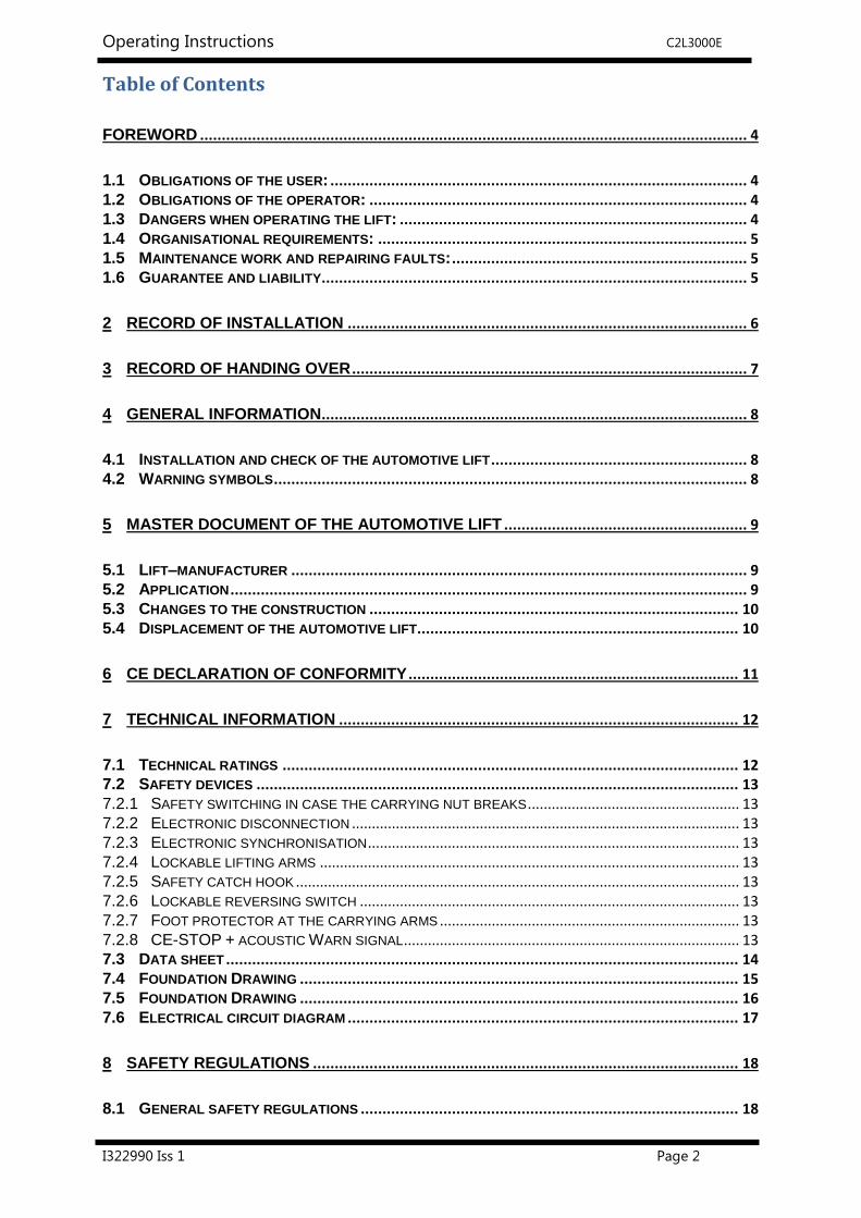
Table of Contents
FOREWORD .............................................................................................................................. 4
1.1 OBLIGATIONS OF THE USER: ................................................................................................ 4 1.2 OBLIGATIONS OF THE OPERATOR: ....................................................................................... 4 1.3 DANGERS WHEN OPERATING THE LIFT: ................................................................................ 4 1.4 ORGANISATIONAL REQUIREMENTS: ..................................................................................... 5 1.5 MAINTENANCE WORK AND REPAIRING FAULTS: .................................................................... 5 1.6 GUARANTEE AND LIABILITY .................................................................................................. 5
2 RECORD OF INSTALLATION ............................................................................................ 6
3 RECORD OF HANDING OVER ........................................................................................... 7
4 GENERAL INFORMATION .................................................................................................. 8
4.1 INSTALLATION AND CHECK OF THE AUTOMOTIVE LIFT ........................................................... 8 4.2 WARNING SYMBOLS ............................................................................................................. 8
5 MASTER DOCUMENT OF THE AUTOMOTIVE LIFT ........................................................ 9
5.1 LIFT–MANUFACTURER ......................................................................................................... 9 5.2 APPLICATION ....................................................................................................................... 9 5.3 CHANGES TO THE CONSTRUCTION ..................................................................................... 10 5.4 DISPLACEMENT OF THE AUTOMOTIVE LIFT .......................................................................... 10
6 CE DECLARATION OF CONFORMITY ............................................................................ 11
7 TECHNICAL INFORMATION ............................................................................................ 12
7.1 TECHNICAL RATINGS ......................................................................................................... 12 7.2 SAFETY DEVICES ............................................................................................................... 13 7.2.1 SAFETY SWITCHING IN CASE THE CARRYING NUT BREAKS ..................................................... 13 7.2.2 ELECTRONIC DISCONNECTION ................................................................................................. 13 7.2.3 ELECTRONIC SYNCHRONISATION ............................................................................................. 13 7.2.4 LOCKABLE LIFTING ARMS ......................................................................................................... 13 7.2.5 SAFETY CATCH HOOK ............................................................................................................... 13 7.2.6 LOCKABLE REVERSING SWITCH ............................................................................................... 13 7.2.7 FOOT PROTECTOR AT THE CARRYING ARMS ........................................................................... 13 7.2.8 CE-STOP + ACOUSTIC WARN SIGNAL .................................................................................... 13 7.3 DATA SHEET ...................................................................................................................... 14 7.4 FOUNDATION DRAWING ..................................................................................................... 15 7.5 FOUNDATION DRAWING ..................................................................................................... 16 7.6 ELECTRICAL CIRCUIT DIAGRAM .......................................................................................... 17
8 SAFETY REGULATIONS .................................................................................................. 18
8.1 GENERAL SAFETY REGULATIONS ....................................................................................... 18
Operating Instructions C2L3000E
I322990 Iss 1 Page 3
8.2 ADDITIONAL SAFETY REGULATIONS ................................................................................... 18
9 OPERATING INSTRUCTIONS .......................................................................................... 19
9.1 POSITIONING THE VEHICLE ................................................................................................. 19 9.2 LIFTING THE VEHICLE ......................................................................................................... 20 9.3 SYNCHRONISATION OF THE LIFT ......................................................................................... 21 9.4 LOWERING THE VEHICLE .................................................................................................... 21 9.5 LED - (VISIBLE DISPLAY) AT THE CONTROL PANEL ............................................................. 22
10 TROUBLESHOOTING ..................................................................................................... 24
10.1 EMERGENCY LOWERING IN CASE OF POWER FAILURE ....................................................... 25 10.2 LOWERING ONTO AN OBSTACLE ....................................................................................... 25 10.3 FUNCTION OF SAFETY DEVICE .......................................................................................... 25 10.4 MANUALLY EQUALIZING THE CARRIAGE ........................................................................... 25 10.5 ADJUSTING THE TOP AND BOTTOM LIMIT SWITCHES .......................................................... 26 10.6 INSPECTION AND MAINTENANCE ...................................................................................... 27 10.7 MAINTENANCE OVERVIEW ............................................................................................... 27 10.8 MAINTENANCE SCHEDULE ................................................................................................ 28 10.9 STABILITY OF THE LIFT ..................................................................................................... 31 10.10 ADJUSTING THE POLYLEX-BELT ..................................................................................... 32
10.11 CARRYING NUT SYSTEM (OPTICAL WEARING DEVICE). ...................................................... 33
11 INSTALLATION AND INITIATION .................................................................................. 34
11.1 INSTALLATION INSTRUCTIONS .......................................................................................... 34 11.2 ERECTION AND DOWELING OF THE LIFT ............................................................................ 34 11.3 WIRING AND POWER CONNECTION ................................................................................... 36 11.3.1 USING CROSS-BEAM AND ASCENDING PIPE: ......................................................................... 36 11.3.2 WITHOUT USING CROSS-BEAM AND ASCENDING PIPE (UNDER FLOOR) ................................ 37 11.4 INSTALLING THE CARRYING ARMS .................................................................................... 37 11.5 INITIATION ........................................................................................................................ 38 11.6 RELOCATION OF LIFT ....................................................................................................... 38
12 CHOICE OF DOWEL LENGTH ....................................................................................... 39
12.1 WITHOUT FLOOR PAVEMENT OR TILE SURFACE ................................................................. 39 12.2 WITH FLOOR PAVEMENT OR TILE SURFACE ....................................................................... 40 12.3 FISCHER – DÜBEL ............................................................................................................ 41 12.4 HILTI - INJECTION ANCHORS ............................................................................................ 42 12.5 FIRST SAFETY CHECK BEFORE INSTALLATION .................................................................. 43 12.6 REGULAR SAFETY CHECK AND MAINTENANCE .................................................................. 44 12.7 EXTRAORDINARY SAFETY CHECK ..................................................................................... 50
13 AFTER SALES SERVICE ................................................................................................ 51
13.1 ON-SITE SERVICE / OVERHAUL / SPARE PARTS ............................................................... 51 13.2 CONTACT DETAILS ..................................................................................................... 51

Operating Instructions C2L3000E
I322990 Iss 1 Page 4
Foreword
Crypton Lifts are the result of over 100 years experience in the automotive industry.
The high quality and the superior concept ensure reliability, a long lifetime and above all, economic
business solution. To avoid unnecessary damage, injury or even death, read the operating instructions
with care and observe the content.
Crypton is not responsible for incidents involving the use for applications other than those for
which they were designed.
Continental Corporation is not liable for any resulting damages. The user carries the risk alone.
1.1 Obligations of the user:
- To observe and adhere to the operating instructions.
- To follow the recommended inspection and maintenance procedures and carry out the prescribed
tests.
- The operating instructions must be observed by all persons working with or around the lift.
- Above all, the chapter entitled “Safety Regulations“ is very important and must be closely adhered
to.
- In addition to the safety regulations stated in the operating instructions manual, the appropriate
safety regulations and the operating procedures of the place of operation must also be considered.
1.2 Obligations of the operator:
The operator is obliged to allow only those persons complying with the following requirements to
work with or around the unit.
- Persons who are familiar with the basic regulations concerning labor safety and accident
prevention and who have been trained to operate the particular unit.
- Persons who have read and understood the chapters concerning safety and warning symbols.
Such persons are required to confirm that they have read and understood the chapter on safety
and warning symbols by signing the appropriate form.
1.3 Dangers when operating the lift:
Crypton lifts are designed and built according to technical standards and the approved regulations
for technical safety. The use of Crypton lifts for purposes other than those for which they were
designed may result in injury or even death.
The lift must only be operated:
- For its intended purpose.
- In faultless condition concerning technical safety.

Operating Instructions C2L3000E
I322990 Iss 1 Page 5
1.4 Organisational requirements:
- The instructions for use are to be kept at the place of operation, easily accessible at all times.
- In addition to the instructions for use, rules pertaining to other regulations i.e. accident prevention
and environmental rules are to be observed and adhered to.
- The owner of the Crypton lifting system must ensure that operators and persons working with
or around the lift occasionally conduct “refresher” courses to ensure that the appropriate operating
procedures and safety precautions are known.
- Personal Protective Equipment (PPE) must be used according to the appropriate regulations.
- All safety and danger signs on or around the lift are to be observed and followed!
- Spare parts must comply with the technical requirements specified by the manufacturer.
This is only warranted with original parts.
- Observe and adhere to the specified time intervals between tests and inspections.
1.5 Maintenance work and repairing faults:
- Adjustments, maintenance and inspections are to be followed according to the time intervals
specified. Details regarding the exchange of parts and components as mentioned in the operating
instructions are to be adhered to.
Such work may only be carried out by expert personnel.
- After maintenance and repair work, loose screws, nuts and bolts must always be firmly
tightened!
1.6 Guarantee and liability
- Our “General conditions of selling and delivering” are enforced.
There will be no guarantee or liability for incidents involving injuries, death or damage to
equipment if these incidents are the result of one or more of the following reasons:
- Inappropriate use of the lift
- Inappropriate installation, initiation, operation and maintenance of the lift.
- Use of the lift while one or several safety devices do not work, do not work properly or are not
installed properly.
- Failure to follow the regulations of the operating instructions regarding transport, storage,
installation, initiation, operation and maintenance of the lift.
- Unauthorized changes to the structure of the lift without first asking the manufacturer.
- Unauthorized changes or adjustments of important components of the lift (e.g. driving elements,
power rating, motor speed, etc.).
- Incorrect maintenance practices.
- Catastrophes, acts of God or external reasons.

Operating Instructions C2L3000E
I322990 Iss 1 Page 6
Fill out, sign and photocopy this sheet and send the original to the lift manufacturer.
The copy remains in the manual.
Continental Automotive Trading UK Ltd
36 Gravelly Industrial Park
Birmingham B24 8TA
United Kingdom
2 Record of installation
The automotive lift
with the serial number:...................................... was installed on:...............................................
at the firm:................................................. …… in:......................................................……….....
The initial safety check was carried out and the lift was started.
The installation was carried out by the operating authority/competent person (please delete as
applicable).
The initial safety check was carried out by a competent person before the initial operation.
The operating authority attests to the correct installation of the automotive lift, the competent person
attests to the correct initial operation.
Used dowels (*): ________________________________ (Type/Name)
Minimum anchorage depth (*) kept: _________________mm � ok
Starting torque (*) kept: __________________________NM � ok
...................... ................................................. ............. ..........................................
Date Name of the operating authority Signature of the operating authority
...................... ................................................. ............ ..........................................
Date Name of the competent person Signature of the competent person
Your customer service: ................................................................................. (stamp)
(*) see supplement of the dowel manufacturers

Operating Instructions C2L3000E
I322990 Iss 1 Page 7
3 Record of handing over
The automotive lift
with the serial number: ............................................ was installed on:...............................
at the firm:................................................. ……... in:.........................................................
The safety was checked and the lift was started.
The persons listed below were introduced after the installation of the automotive lift. The introduction
was carried out by an erector of the lift manufacturer or from a franchised dealer (competent person).
............................................ ..................................................... ............................................
Date Name Signature
............................................ ..................................................... ............................................
Date Name Signature
............................................ ..................................................... ............................................
Date Name Signature
............................................ ..................................................... ............................................
Date Name Signature
............................................ ..................................................... ............................................
Date Name Signature
............................................ ..................................................... ............................................
Date Name Signature
.................................. ......................................................... ......................................................
Date Name of the competent person Signature of the competent person
Your customer service: ............................................................................................... (stamp)

Operating Instructions C2L3000E
I322990 Iss 1 Page 8
4 General information
The document “Operating Instructions and Documentation” contains important information
about installation, operation and maintenance of the automotive lift.
- Confirmation of installation of the automotive lift is recorded on the “Record of installation”
form and must be signed and returned to the manufacturer.
- Confirmation of initial, regular and extraordinary service/safety checks is recorded in the respective
review forms. The forms are used to document the checks. They should not be removed from the
manual.
All changes to the structure and any change of location of the automotive lift must be registered
in the “Master document” of the lift.
4.1 Installation and check of the automotive lift
Only specialized staff/specialists are allowed to perform repair and maintenance work, and only
such specialists are allowed to conduct safety checks on the lift. For the purpose of this document,
these specialists will be called “experts” and “competent persons”.
Experts are persons (for example, self-employed engineers) who have received instructions and have
the appropriate experience to check and test automotive lifts. They are aware of the work involved and
know the accident prevention regulations.
Competent persons are persons who have acquired adequate knowledge and experience with
automotive lifts. They have completed the appropriate training provided by the lift manufacturer
(for example, the servicing technicians of the manufacturer or dealer are regarded as competent).
4.2 Warning symbols
The three symbols below are used to indicate danger and other important information. Pay attention
to areas on and around the lift that are marked with these symbols.
Danger! This sign indicates danger. Ignoring this warning may result in injury or
even death.
Caution! This sign cautions against possible damage to the automotive lift or
other material objects in the case of improper use.
Attention! This sign indicates an important function or other important
information regarding the operation of the lift.

Operating Instructions C2L3000E
I322990 Iss 1 Page 9
5 Master document of the automotive lift
5.1 Lift–manufacturer
Continental Automotive Trading UK Ltd
36 Gravelly Industrial Park
Birmingham B24 8TA
United Kingdom
5.2 Application
The automotive lift C2L3000E is a lifting mechanism for lifting motor vehicles with a laden weight of up
to 3000 kg. The maximum load distribution is 2:3 in or against drive in direction.
The automotive lift is only designed for servicing vehicles. It is not allowed to carry persons with the
lift.
It is not allowed to put the load on one or two carrying arms. It is not allowed to install the standard
automotive lift in a hazardous location or washing bays.
After changes to the construction and after major repairs to the component parts, the lift of an expert
re-examined and changes are confirmed.
When changing the site, the lift of a competent person re-examined and changes are confirmed.
The operating instruction and the instruction for maintenance have to be observed.
Lifting Arm Variants Standard Lifting Arms Optional Mini – Max Arms
C2L3000E 590-900 mm 600-980 mm
940-1495 mm 1000-1480 mm

Operating Instructions C2L3000E
I322990 Iss 1 Page 10
5.3 Changes to the construction
Changes to the construction, expert review, resumption of work (date, type of change, signature
of the expert)
..............................................................................................................................................................
..............................................................................................................................................................
..............................................................................................................................................................
Name and address of the expert
................................ ......................................................................................
Place and date Signature of the expert
5.4 Displacement of the automotive lift
Displacement of the automotive lift, review by competent person, resumption of work (date,
type of change, signature of the competent person)
..............................................................................................................................................................
..............................................................................................................................................................
..............................................................................................................................................................
Name and address of the competent person
........................................................... ............................................................
Place and date Signature of the competent person
Operating Instructions C2L3000E
I322990 Iss 1 Page 11
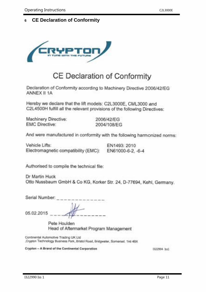
6 CE Declaration of Conformity

Operating Instructions C2L3000E
I322990 Iss 1 Page 12
7 Technical information
7.1 Technical ratings
Capacity 3000 kg
Load distribution max. 2:3
in or against the drive in direction
Lifting time approx. 40 sec
Lowering time approx. 40 sec
Lifting height max.1880mm (short version)
max. 2085mm (long version)
Line voltage in 400 volt 3 phase, 50Hz
Power rating 2 x 1.5kW
Motor speed 1420 rotation/min
Sound level LpA ≤ 70 dB
Connection by customer 3~/N+PE, 400V, 50 Hz
fuse T16A (time-lag fuse)
Observe the respective country regulations
Optional energy set Air pressure: 6-10 bar
Plug: 240v / 50Hz
Important note!
the lifting platform will be handed over without connection to the available electricity
supply, after being tested for function and safety.
A plug and socket connection, in direct proximity of the lifting platform, is the customers
responsibility.
The plug must be:
a) Positioned at a height which can only be reached with a device, such as a ladder, or
b) A lockable mains switch.

Operating Instructions C2L3000E
I322990 Iss 1 Page 13
7.2 Safety devices
7.2.1 Safety switching in case the carrying nut breaks
Examination of the carrying nut with a wear-pin into the lifting carriage.
7.2.2 Electronic disconnection
If the final position is reached, the lifting platform switched-off
7.2.3 Electronic synchronisation
Safety device against unequal run of the lifting carriage
7.2.4 Lockable lifting arms
Protection against unintentional adjusting of the arms
7.2.5 Safety catch hook
Safety device against repeated raising if the lifting nut is broken
7.2.6 Lockable reversing switch
Safety device against unauthorized use
Optional:
7.2.7 Foot protector at the carrying arms
Safety device to avoid crushing
7.2.8 CE-STOP + acoustic Warn signal
Safety device to avoid crushing
Operating Instructions C2L3000E
I322990 Iss 1 Page 14
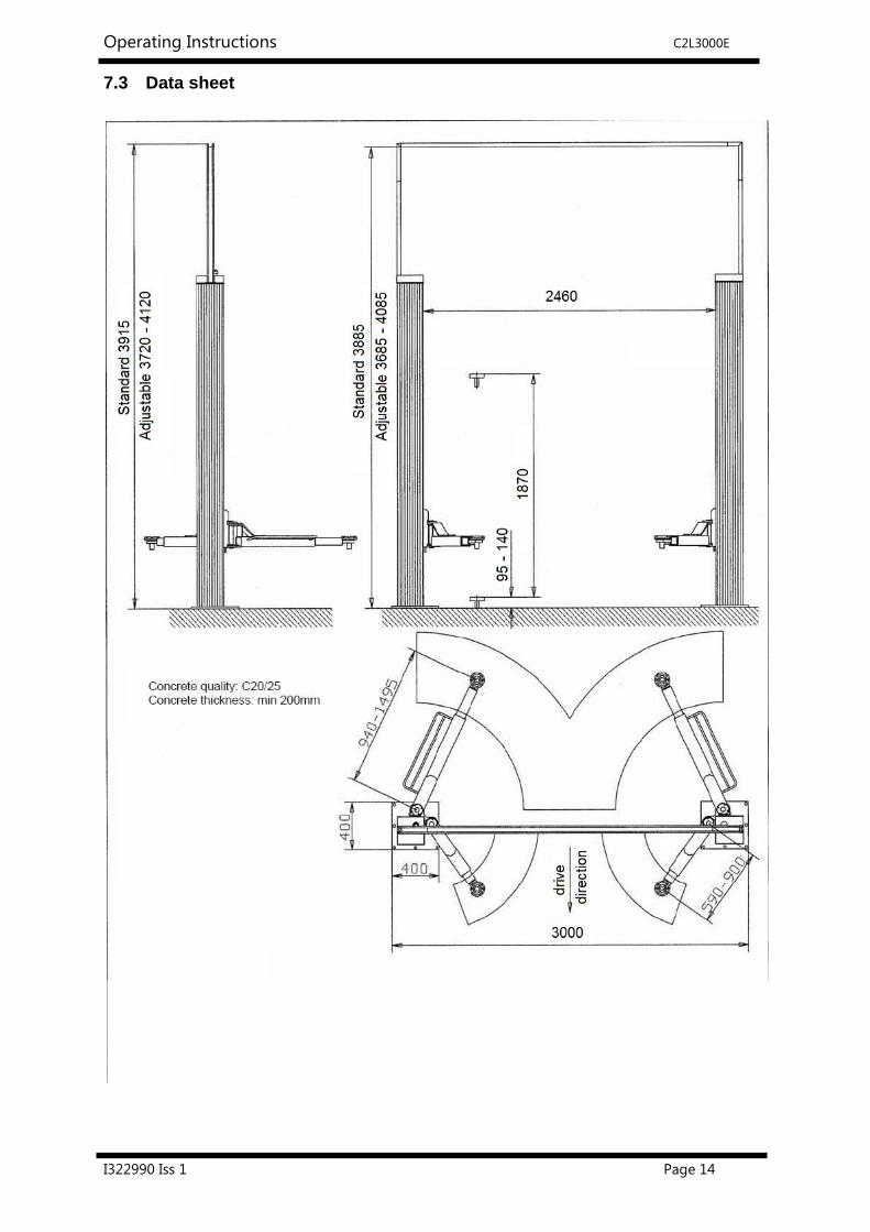
7.3 Data sheet

Operating Instructions C2L3000E
I322990 Iss 1 Page 15
7.4 Foundation Drawing

Operating Instructions C2L3000E
I322990 Iss 1 Page 16
7.5 Foundation Drawing

Operating Instructions C2L3000E
I322990 Iss 1 Page 17
7.6 Electrical circuit diagram

Operating Instructions C2L3000E
I322990 Iss 1 Page 18
8 Safety regulations
If you use the automotive lift, the following European regulations are to be considered:
BGG945: Examine of automotive-lifts; BGR500 Using automotive-lifts; (VBG14).
8.1 General safety regulations
When using your garage equipment, basic safety precautions should always be followed. This
includes the following:
Read all instructions.
Care must be taken as burns can occur from touching hot parts.
Do not operate equipment with a damaged cord or main disconnect switch until it has been
examined by a qualified service technician.
Always disconnect equipment from electrical outlet when not in use.
To reduce the risk of fire, do not operate equipment in the vicinity of open containers of
flammable liquids (gasoline).
Adequate ventilation should be provided when working on operating internal combustion
engines.
Keep hair, loose clothing, fingers and all parts of the body away from moving parts.
To reduce the risk of electric shock, do not use on wet surfaces or expose to rain.
Use only as described in this manual. Only use the manufacturer’s recommended attachments.
SAVE THESE INSTRUCTIONS
8.2 Additional safety regulations
The following regulations are particularly important:
• The laden weight of the lifted vehicle must not exceed 3000 kg for the automotive lift.
• The automotive lift must be in its lowest position (fully collapsed), before the vehicle can be driven
onto the lift. Only then can the vehicle be lifted.
• While working with the lift the operating instructions must be followed.
• Vehicles with low clearance or vehicles that are specially equipped should be pre tested to ensure
that they clear the lift ramp to avoid damage.
• Only trained personnel over the age of 18 years old are to operate this lift.
• No one is to stand within the working area (danger area) during lifting and lowering
• No one is to be raised or lowered either directly or in a vehicle by the automotive lift.
• No one is to climb onto the automotive lift or onto an already raised vehicle.
• The automotive column lift must be checked by an expert after changes in the construction have
been made.
• The main switch must be switched off and locked before work on the vehicle can commence. This
is a safety precaution to ensure that the lift does not move during work.
• The main switch must be switched off and locked before any maintenance or repair work on the
automotive lift itself can be carried out.
• During lifting or lowering the operator must observe the vehicle to ensure that the vehicle and the lift
are functioning correctly.
• Installation of the standard-mobile column lift in hazardous or dangerous locations such as washing
bays is dangerous and is not allowed.
• Check the centre of gravity of the vehicle if heavy parts (eg the motor) are removed.
• If heavy parts must be removed (motor) the centre of gravity will change. Secure the vehicle before
removing parts to avoid the possibility of the vehicle becoming insecure.
Do not position a magnet in the vicinity of the operating column or near the control unit.
Otherwise a malfunction can occur and synchronisation may not be possible!

Operating Instructions C2L3000E
I322990 Iss 1 Page 19
9 Operating instructions
The safety regulations must be observed and adhered to while working with the
automotive lift. Read the safety regulations carefully before working with the lift!
9.1 Positioning the vehicle
Position the vehicle as described at the picture (Pic. A and Pic. B). (necessary only with
asymmetrical lifting arms)
.
Position the adjustable rubber pads under the vehicle which are described by the vehicle
manufacturer. (see pic.1)
Pic. A) Position the column between
the steering wheel and the car-door
Pic. B) Drive the vehicle into the
centre of lifting platform.
pic 1: Version with Mini-Max lifting arms
Position the pads under the described
points of the vehicle.
Pic 2: Press the lever to position the pads
under the pickup points.
Examine the position of the teeth.
They must engages reliably in the
intended position.
Otherwise the "mini-max" can fall
down into the lowest position.

Operating Instructions C2L3000E
I322990 Iss 1 Page 20
Examine the locking device of the arms. They must be locked before raising the vehicle with
the lift.
After every lowering of the vehicle in the lowest position, examine the safe position of the
lifting arms under the vehicle. If necessary adjust it again.
Control the dangerous places of the lift and be sure that there are no objects or people in the
immediate area of the lift or on the lift.
9.2 Lifting the vehicle
Lift the vehicle free. Check the position of the pads under the vehicle. Activate the operating
element => “Lifting“ (see pic. 4)
If the wheels are free, stop the lifting procedure and check the sit of the pads again.
Lift the vehicle on the working height.
Observe the lifting procedure.
Check the pads under the vehicle again, otherwise the vehicle can fall down.
The automotive-lift can adjust several times depending upon distribution of the load.
Check the fixing device of the arms. The device must lock.
pic 4: control panel
If the top or bottom limit switches have been activated, red LED’s light up.
Do not alternately raise or lower the lift several times if the red LED’s are lit, otherwise
damage can occur.
Pic 3: Press the rear lever to unlock the pads.
Operating Instructions C2L3000E
I322990 Iss 1 Page 21
9.3 Synchronisation of the lift
The lift is equipped with an electronic synchronisation.
Potentiometers in the columns recognize the actual-position of the spindle. They recognise
the height of the lift.
If one lifting carriage is faster than the other, the electronic control system stops the faster
carriage until both carriages are at the same height again. The allowable range is 18 mm.
9.4 Lowering the vehicle
Ensure there are no obstructions, or people, in the immediate area, or upon, the lift before
operating.
Lower the lift to a working height, or until the carrying arms reach their lowest position.;
Activate the operating element => “Lowering“
The lift can adjust several times depending upon distribution of the load.
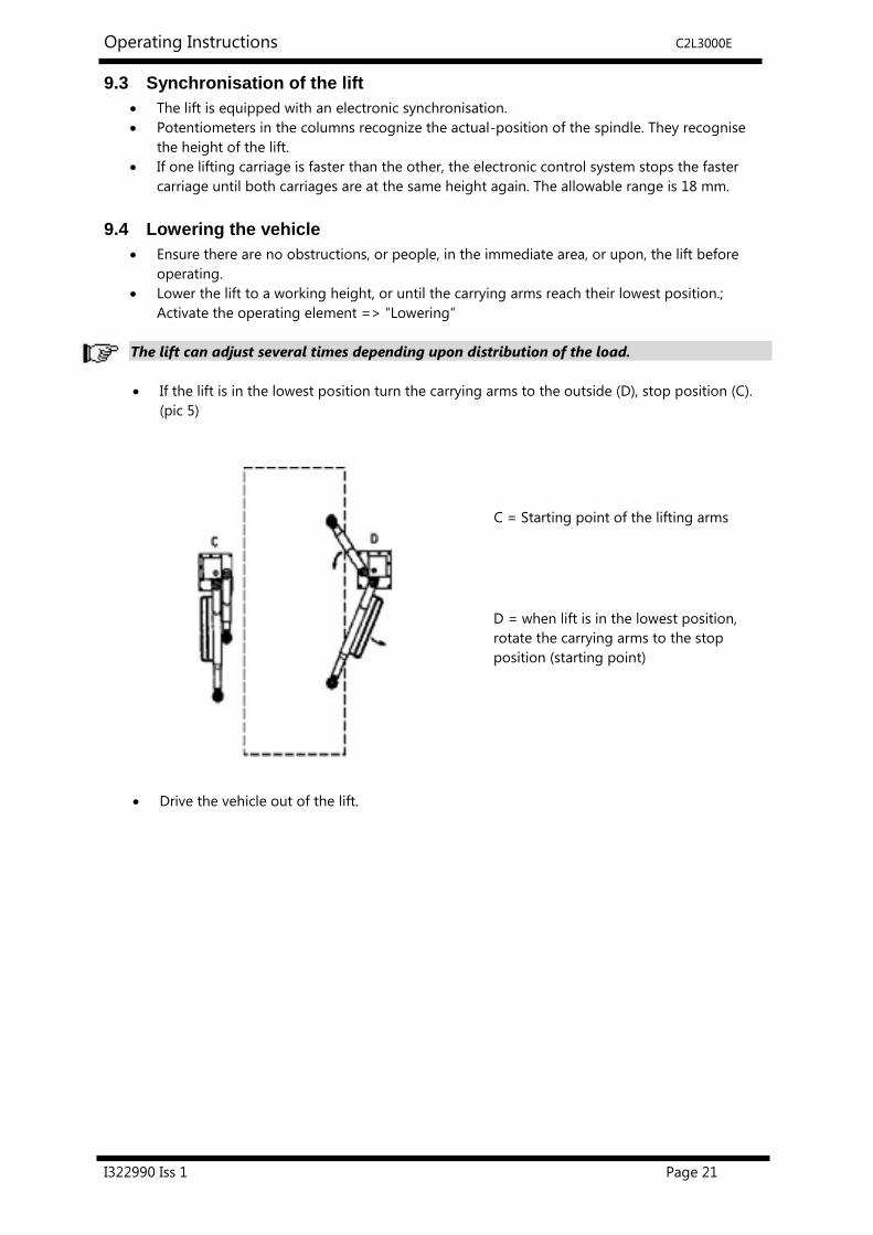
If the lift is in the lowest position turn the carrying arms to the outside (D), stop position (C).
(pic 5)
Drive the vehicle out of the lift.
C = Starting point of the lifting arms
D = when lift is in the lowest position,
rotate the carrying arms to the stop
position (starting point)

Operating Instructions C2L3000E
I322990 Iss 1 Page 22
9.5 LED - (visible display) at the control panel
A position measuring system monitors the lifting and lowering process. Additional the functions are
made by a visibly display. Find the explanations following:
pic 6: control panel at the column
Indications at standard function
• raising up:
the following LED lighten: lifting, K1,K2 - lowering glow
• lowering:
the following LED lighten: lowering, K1,K2 – lifting glow
• top position is reached (top limit switch is active):
the following LED lighten: OA1, OA2, lifting – lowering glow
• lower position is reached (below limit switch is active):
the following LED lighten: UA1, UA2, lowering – lifting glow
If following LED s are alight:
OA1 - LED red - top limit switch is active (master side)
K1 - LED green - Motor contactor is active (master side)
UA1 - LED red - below limit switch is active (master side)
OA2 - LED red - top limit switch is active (slave side)
K2 - LED green - Motor contactor is active (slave side)
UA2 - LED red - below limit switch is active (slave side)
Heben - LED green - the lift is raising
Senken - LED green - the lift is lowering

Operating Instructions C2L3000E
I322990 Iss 1 Page 23

Operating Instructions C2L3000E
I322990 Iss 1 Page 24
10 Troubleshooting
If the lift does not work properly, the reason for this might be quite simple. Please check the lift
for the potential reasons mentioned on the following pages. If the cause of trouble cannot be
found, please call the technical service of the dealer.
A simple fault delimitation can be carried out at the LED-display of the operating unit.
(see the step 5.5 LED-Display visibly at the operating unit).
Repairs and examination of safety devices and electrical components of the lift must
only be carried out by electrical experts.
Problem: The lift does not raise or lower!
Possible causes: Remedy:
No electrical power supply Examine the power supply
The main switch is not switched on Examine the main switch
The reversing switch is defective Examine the reversing switch
The fuse is faulty Examine the fuse, replace it if necessary
The feed line is cut Examine the feed line
The motor is overheated Let it cool down
The plug connection between the motors are loose Examine the plugs
The lift is not in the regulation range Equalize manually (see “manual equalization of
carriage” section)
V-Belt is broken or defective Shut off the lift. Replace the V-belt and adjust (see
“adjust the Polylex-belt” section)
Motor defective Follow “emergency lowering” section
The lift is in the lowest position. The safety device
(catch hook) is active and the lift is no longer in the
regular range
Lifting nut is defective. Call your service partner.
Problem: The lift does not raise!
possible causes: remedy:
Only 2 phases active
Examine by an electrician
V-Belt is broken or slack Shut off the lift. Replace the V-belt and adjust it
again (see “adjust the Polylex-belt” section)
The automotive-lift is in the lowest position. The
safety device (catch hook) is active and the lift is no
longer in the regular range
Lifting nut is defective. Call your service partner.
Top limit switch is active Only lowering procedure is possible
Problem: The lift does not lower!
possible causes: remedy:
The bottom limit switch is active Only lifting procedure is possible
The lifting arms is stuck on a obstacle and the lift is
no longer in the regular range. The lift is switched
off.
Equalise the lift manually

Operating Instructions C2L3000E
I322990 Iss 1 Page 25
10.1 Emergency lowering in case of power failure
In case of power failure the lift cannot be lowered with the motors. The lift must be lowered manually.
Emergency lowering must only carried out by persons who have been trained to use the
lift. Please refer to the section “Lowering the vehicle”.
Procedure – emergency lowering
Disconnect from the mains; switch off the main switch and lock it.
Remove the cover of the v-belt pulleys.
Lower the lift by turning the nuts (each side alternately 5 cm) until the lift has reached lowest
position.
After emergency lowering: do not use the lift until faulty parts have been replaced.
10.2 Lowering onto an obstacle
If the lifting arm, or the lifting carriage, is lowered onto an obstacle, the motor from this side is locked.
The lift is switched off if the lifting carriage is outside the allowable range (approx. 64 mm).
The motor is also protected by a temperature control, which interrupts the electrical circuit when it is
overloaded. The lift cannot be operated until the motor cools down. This takes approximately 5 – 10
min. depending on the outside temperature.
After the motor has locked, check the V-belt, and if necessary replace it. Then call your service-partner.
10.3 Function of safety device
The lift is equipped with safety switching, which controls the wear of the main nut.
If the lifting nut breaks, a safety nut which is positioned loose in the spindle, carries the load. This
ensures that, in the event of a broken nut, the lift can only be lowered to the lowest position.
Once the lift has reached the lowest position it is not possible to raise it again.
The lifting carriage of the broken side gets mechanically locked with a catch hook. During the
lifting procedure, if the other side is driven out of the allowable range, the lift is stopped and cannot
be operated anymore. Call your service-partner.
If the safety device is activated, switch off the lift and contact your service partner!
Switch off the main switch for all repairs and maintenance!
The electrical system should only be opened by trained persons!
10.4 Manually equalizing the carriage
The lift is fitted with a position measuring system which ensures that the lifting carriages are
synchronized. The electronic control detects if one lifting carriage is approx. 18 mm below the other.
The motor of the highest carriage is stopped until both carriages are at the same height again.
If the lifting carriages are driven out of the allowable “switch off” range, (approx. 64 mm) then the
electronic control switches off the lift.
To restore the normal function of the lift you must then manually equalize the carriages:
Remove the V-Belt pulley cover at the top of the lift.
Equalize the lift by manually turning one nut (at the top of the spindle) until both carriage are
at the same height.

Operating Instructions C2L3000E
I322990 Iss 1 Page 26
10.5 Adjusting the top and bottom limit switches
The operating unit of the lift is equipped with potentiometers. One is for the top limit switch and one
is for the bottom limit switch.
For safety reasons, the potentiometer must only be adjusted by a competent trained person.
The potentiometers must be set-up when assembling the lift
Disconnect the main plug before any maintenance or repair.
Pic. 7: Version without Ce-Stop
The Illustration can vary, depending the lift type
Pos. 3 Potentiometer for the upper end-point
Pos. 4 Potentiometer for the lower end-point
pic 8: Version with CE-Stop
Incorrect adjustments could cause lift malfunctions.
This could endanger your life, the lift and vehicles.
Loosen screws of the operating unit and pull it careful out of the column.
Turning Potentiometer 3 anticlockwise raises the upper end-point, so the lift stops later.
Turning Potentiometer 3 clockwise lowers the upper end-point, so that the lift stops earlier.
Turning Potentiometer 4 anticlockwise raises the lower end-point, so that the lift stops earlier.
Turning Potentiometer 4 clockwise lowers the lower end-point, so that the lift stops later.
After the adjusting, do not raise or lower to the end position. The lift can lock or jam!
Adjust the potentiometer a small amount, then operate the lift.
Repeat this process until the correct end position is achieved.
Take care not to damage the rubber seal behind the cover, otherwise the IP54 protection
against liquids cannot be ensured.
Potentiometer for
the upper end point
Potentiometer for
the lower end point
Potentiometer for
the end point
Loudspeaker

Operating Instructions C2L3000E
I322990 Iss 1 Page 27
10.6 Inspection and Maintenance
Before conducting any maintenance work, ensure that there is no risk to the safety of
people, or damage to equipment in the vicinity of the lift.
To maximize productivity and to ensure that the lift remains safe and functional, maintenance
contracts are available from Crypton.
Service must be carried out at regular 3 month intervals by the operator in accordance to the following
procedures. If the lift is continuously operated in a dirty environment, the maintenance rate must be
increased.
During daily operation the lift should be closely observed to ensure that it is functioning correctly. In
the case of a malfunction or leakage, Crypton Technical Support must be informed.
European legal guidelines : BSV (Prescription of working tools) + BGR500 (Work with
working tools)
10.7 Maintenance Overview
Lubrication and maintenance plan:
For example: 1B = grease every six month with a multipurpose grease
5C = clean every month with air pressure

Operating Instructions C2L3000E
I322990 Iss 1 Page 28
10.8 Maintenance schedule
Before beginning any maintenance work isolate the power supply and lock the main
switch. Secure the danger area around the lift and protect against unintentional lowering
Location Type Maintenance Plan Period
Check the condition of the serial plate, sticker and
short operating instruction. Clean and, if necessary,
replace.
Daily
A
Remove the spindle cover (g).
Lubricate the nipples with a multipurpose grease.
(eg: Auto Top 2000 LTD. Agip).
Avoid too much grease.
Minimum every 12
months
B
Check condition the Poly-V belt. and if necessary
replace.. Follow the section describing V-Belt
replacement.
Minimum every 12
months
C
Check the spindle for wear Minimum every 12
months

Operating Instructions C2L3000E
I322990 Iss 1 Page 29
D
Oil the spindle and the lubricating felt between the
carrying nut and the spindle.
After applying, raise and lower the lift twice whilst
loaded.
Oil the nut between the column (c) and the cover
(g).
Regular lubrication ensures smooth operation of
the lift.
Do not use normal adhesive oil. The formation of
resin can occur resulting in damage.
We recommended SAE 15W40, or equivalent
After installation
and then minimum
once a month.
E
Check the carrying nut (optical wearing device).
Remove the spindle cover and inspect the carrying
plate pin. It should be even with the top edge of
the carrying plate (upper side of the lifting
carriage; built-in state).
If the pin is more than 2 mm from the top edge,
then both the carrying nut and the sequence nut
must be replaced.
Minimum every 12
months
F
Examine the condition and function of the spindle
centering (after a delay in running)
If necessary. adjust it by filing.
When it is not possible to adjust the spindle
centering anymore, change it.
Set the initial spindle centering with a torque
key at 4 Nm. Gap should be approx. 1mm
with the half shells touching at the back
Switch off the main switch.
Take one hand on the spindle and rotate it
easily back and forth.
Whilst rotating, tighten the hose clamp with
the torque key until it’s not possible to rotate
with one hand.
Then use both hands to rotate the spindle.
The spindle centering is correctly adjusted
when the spindle can be rotated with both
hands.
Carry out the same procedure at the second
column.
If the spindle can still be easily rotated with
one hand, despite tightening the spindle
centering, then it is necessary to remove
some of the cut edge of the spindle centering
with a file. Otherwise the spindle centering
will need to be replaced.
Note: After this procedure, both lifting carriages
must be level. If necessary, adjust the spindle
manually. (see section “manually equalizing the
carriage”)
Minimum every 12
months
1 mm
Set 4 Nm
Do not saw
plastic parts.
File only!

Operating Instructions C2L3000E
I322990 Iss 1 Page 30
G
Check condition and function of the locking device
and crown gear of the lifting arms. In case of
damage replace it.
Minimum every 12
months
H
Check the DU-bearing for wear.
Oil the bearing with SAE 15W40, or equivalent
Minimum every 12
months
J,K,O
Check condition and function of the lifting arms
and threaded bolts.
Grease the bolts and the threaded liberally.
Minimum every 12
months
L
Check condition and function of the foot
protection of the lifting arms.
Replace if damaged.
Daily
M
Check the condition and function of the rubber
pads.
Replace if damaged.
Daily
N
Remove the spindle cover (g) at the column.
Lubricate the second lifting nut nipple through the
access hole in the lifting carriage.
Use multipurpose grease.
Note: do not apply excessive amount of grease, as
this will reduce the efficiency of the lift.
Monthly
P
Check the condition and function of the sliding
blocks of the lifting carriage and also the sliding
surfaces of the columns.
After cleaning apply lubrication..
Minimum every 12
months
MINI-MAX
lifting arm
To ensure troublefree operation, regularly clean
the Mini-Max.
Use an air line to blow dirt from the bolts
Test the roll on wear.
Check the safety screws. (The screw is loosely
fastened and kept in position with adhesive -
Loctite)
The screw cannot be too tight otherwise the
mechanism will not operate smoothly.
Clean the surface and spray it.
After the cleaning, lubricate the surfaces (for
example: the bolt) with oil.
Check the safety sheet.
monthly
Q
Check that all screws and bolts are all torqued
correctly, as below:
Minimum every 12
months

Operating Instructions C2L3000E
I322990 Iss 1 Page 31
General
Cleaning
Regular cleaning of all kinds of dirt is the best
protection against wear and corrosion, and will
prolong the life of the lift
Dirty deposits that can cause rust include:
de-icing salt
sand, pebble stone, natural soil
water
humidity caused by insufficient ventilation
Clean the lift and the floor area with a non-
aggressive and non-abrasive detergent. Use a
gentle detergent to clean the parts, such as
standard washing-up liquid and lukewarm water.
Do not use steam jet cleaners.
Monthly
Welded joints
Inspect all welded joints on the lift for cracks.
If any cracks are found on the lift cease use
immediately.
Switch-off power and lock the main switch
Contact your service partner.
Minimum every 12
months
Paintwork and
surface finishes
Any damage to external surfaces, must be
immediately repaired, otherwise permanent
damage to the powder-coated surface may result.
Corrosion can result from the accumulation of
moisture or poor ventilation.
Corrosion can also result from mechanical damage,
wear, aggressive sediments (de-icing salt, liquids)
or insufficient cleaning.
Repair and clean damaged painted areas with
an abrasive paper (grain 120), then cover the
damaged area with a suitable paint (observe
the RAL Number).
Zinc surfaces can be repaired with abrasive
paper (grain 280). ), then sealing with a
suitable paint (observe the RAL Number).
Minimum every 12
months
Electrics
Check the electrical components for damage.
- plug / male plug
- Reversing switch and LED lights
Check the condition of all electrical cables.
cables and wires must be secured, so that
they are not crushed or kinked, and that they
do not touch rotating components (e.g. V-
belt pulley contact, etc.).
Check for damage or wear.
Optional Energy set:
Check pneumatic connection
Minimum every 12
months
10.9 Stability of the lift
Check the dowels with a torque key as described by the dowel manufacturer. Follow the dowel
manufacturer instructions.

Operating Instructions C2L3000E
I322990 Iss 1 Page 32
10.10 Adjusting the Polylex-belt
If the V-belt is replaced, the V-belt must be re-adjusted:
Remove the cover of the Vbelt.
Pic.12: cover of the belt (version with raising pipe)
1: column
2: raising pipe
3: cover of the belt
4: spindle
The new V-belt tension must be adjusted at the stretch device. (pic.13). Loosen the three screws at the
motor. (pic. 13, No.1). The belt can be loosened or tightened at the screws. (pic.14, No.2).
Pic.13: position of the belt
1: raising pipe (optional)
2: stretch device
3: V-belt pulley
4: Polyflex-belt
5: shaft of the motor
pic.14: adjust the belt tension
1: the three screws of the motor
2: adjusting screws
The belt tension can be adjusted with the help of an accessory. (pic. 14; This accessory can be
ordered from Crypton).
Pic 15: accessory
Operating Instructions C2L3000E
I322990 Iss 1 Page 33
Put the device on a solid flat surface. Push it down until the pin is also on the flat surface.
Put the clock on zero – turn the clock dial until the indicators are on zero.
Put the device on the V- belt. The indicator of the clock may only move between a tolerance of 1 to
1.5mm.
pic16: measuring instrument
pic 17: Put the measuring device on the V-belt
Bring the screws back to their initial position.
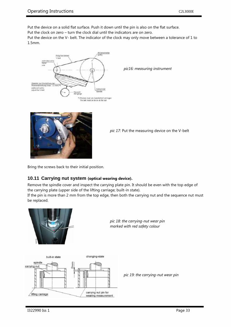
10.11 Carrying nut system (optical wearing device).
Remove the spindle cover and inspect the carrying plate pin. It should be even with the top edge of
the carrying plate (upper side of the lifting carriage; built-in state).
If the pin is more than 2 mm from the top edge, then both the carrying nut and the sequence nut must
be replaced.
pic 18: the carrying-nut wear pin
marked with red safety colour
pic 19: the carrying-nut wear pin

Operating Instructions C2L3000E
I322990 Iss 1 Page 34
11 Installation and Initiation
pic20
11.1 Installation instructions
The installation of the lift must be carried out by trained technicians of the manufacturer or its
distribution partner. The installation has to be done according to this instruction.
The lift must not be installed in hazardous locations or washing areas.
Before installation a suitable foundation must be proven or constructed.
The surface must be level
The foundations must be to a frost resistant depth.
An electrical supply 3~/N+PE, 400 V, 50 Hz must be provided. The supply line must be protected
with 16 Ampere time lag (VDE0100 European regulation). The minimum diameter amounts to 2,5
qm².
The supply cable usually enters the top of the operating column, however it is possible to enter
through a hole in the base of the column. The cable must be secured with cable bushing.
Do not fold the cables!
After assembly of the lift, the protective grounding must be examined according to International
Electronic Commission (IEC) guidelines (60364-6-61) before first start-up by operators. Also an
insulation resistance examination is recommended.
11.2 Erection and doweling of the lift
Before installation of the lift, secure the area preventing access to unauthorized persons.
Use devices such as cranes, fork lift trucks and supports to transport the lift and avoid
accidents.
The customer is responsible for preparing the ground ready for installation and the condition of the
local site (for example: the ground under the foundation).
Concrete with a minimum quality of C20/25 and a depth according to the Crypton foundation
drawing..
The installation site must be individually specified by the planning architect or by a suitably qualified
engineer.
In case of doubt, a test boring should be carried out and a dowel inserted. The dowel must be
tightened to a torque value, which is specified by the dowel manufacturer.
If there are any defects (such as cracks or hairline cracks) in the zone of influence Ø200 mm, the
foundation cannot be used to install the lift on it.

Operating Instructions C2L3000E
I322990 Iss 1 Page 35
pic 21: complete view: automotive lift with
ascending pipe and traverse.
A foundation must be constructed in accordance with the data sheet “foundation plan”. The surface
between lift and concrete floor must be level.
pic.22: doweling
1: column
2: base plate
3: dowel
As protection against liquids, put a thin foil between the base plate and concrete before doweling.
The gap between base plate and workshop soil should be filled with silicone after doweling.
In order to position the dowels correctly, drill through the guide holes in the base plates (pic.22).
Clean out the holes with pressure air before inserting the dowels. Crypton recommends safety dowels
from various manufacturers (under license).
Follow the specific instructions of the dowel manufacturer (see following pages).
Operating Instructions C2L3000E
I322990 Iss 1 Page 36
Set up the columns, in the correct position, with a spirit level.
If necessary use thin metal sheets between the base plate and the floor, until the lift is in the
correct vertical position.
Tighten the dowels with the torque wrench. Observe the instructions of the dowel manufacturer.
Each dowel must be tightened with the specified torque. Otherwise the normal operation of
the lift cannot be guaranteed.
When the dowel is tightened with the specified torque, the curved washer lies flat on the base
plate. This indicates that the dowel is correctly tightened.
11.3 Wiring and power connection
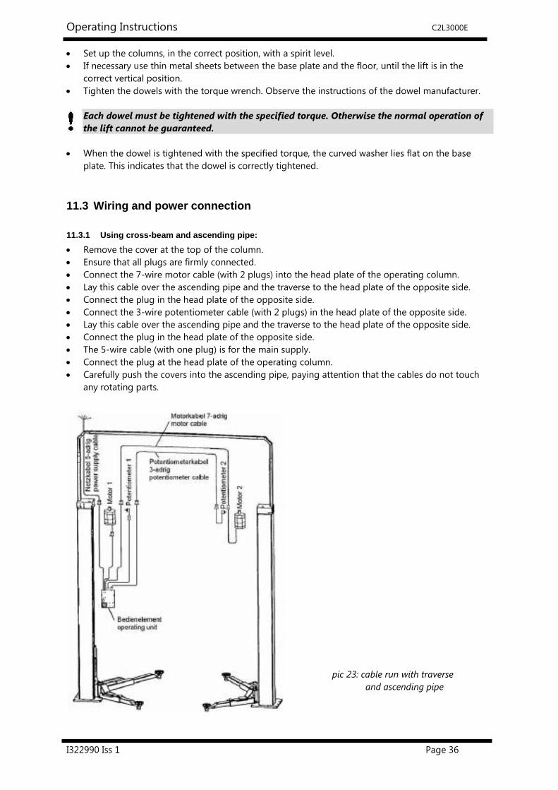
11.3.1 Using cross-beam and ascending pipe:
Remove the cover at the top of the column.
Ensure that all plugs are firmly connected.
Connect the 7-wire motor cable (with 2 plugs) into the head plate of the operating column.
Lay this cable over the ascending pipe and the traverse to the head plate of the opposite side.
Connect the plug in the head plate of the opposite side.
Connect the 3-wire potentiometer cable (with 2 plugs) in the head plate of the opposite side.
Lay this cable over the ascending pipe and the traverse to the head plate of the opposite side.
Connect the plug in the head plate of the opposite side.
The 5-wire cable (with one plug) is for the main supply.
Connect the plug at the head plate of the operating column.
Carefully push the covers into the ascending pipe, paying attention that the cables do not touch
any rotating parts.
` pic 23: cable run with traverse
and ascending pipe

Operating Instructions C2L3000E
I322990 Iss 1 Page 37
11.3.2 without using cross-beam and ascending pipe (under floor)
It is possible to lay the cable under the floor.
In this case, the traverse and ascending pipes are not required.
Construct a foundation in accordance with the relevant drawing.
The opening for the cable is in the base plate of the lift.
Pay attention to the cable when you mount the column.
Pass the cable through the empty pipe before positioning the column.
Move the column to the installation place. Lay the cable through the hole in the base plate to the
head plate of the column. Raise the column.
Connect the cables (Plugs) in accordance with the drawing.(pic.24)
Pay attention that the cables do not touch any rotating parts.
pic 24: cable run without
traverse and ascending pipe
11.4 Installing the carrying arms
Secure the carrying arm bolts with the enclosed Seeger circlip ring.
The carrying arms must be secured at both sides, otherwise a correct connection between
the lift carriage and the carrying arm cannot be guaranteed.
Raise and lower a vehicle, with the lift, several times
Tighten the dowels a second time with the correct torque.

Operating Instructions C2L3000E
I322990 Iss 1 Page 38
11.5 Initiation
A safety check must be carried out before initiation using the form:
First safety check.
If the lift is installed by a competent person, he or she must perform the safety check. If
the operator installs the lift by him or herself, he or she must instruct a competent person to
perform the safety check.
A competent person must
a) confirm that the lift operates correctly in the installation record and the safety check form
b) authorizes the use of the lift.
After installation, please send the completed installation record to the manufacturer.
11.6 Relocation of lift
If the lift is moved to a new location, the new site has to be prepared according to the original
installation instructions. The relocation should be carried out respecting the following points:
Position the carriage to medium height.
Disconnect the power supply to the lift.
Remove the cover.
Remove carrying arms.
Disconnect the plugs.
If necessary, remove the ascending pipe and the traverse.
Loosen the dowels.
Install the lift in accordance with Section “ Installation and Initiation”
Always use new dowels, the original ones cannot be re-used.
A safety check must be performed by a competent person, before re initiation. Use the sheet
“Regular safety check”.
Safety check
The safety check is necessary to guarantee the safety of the lift during use. It has to be carried out in
the following situations:
1. Before the initial operation, after the first installation.
Use the form “First safety check before initiation”
2. At regular intervals after the initial operation, at least every 12 months.
Use the form “Regular safety check at least every 12 months”
3 Every time the construction of that particular lift has been changed.
Use the form “Extraordinary safety check”
The first and the regular safety check must be performed by a competent person.
It is also recommended to carry out a service on the lift at this time.
After the construction of the lift has been changed (eg changing the lifting height or
capacity) and after serious maintenance work (eg welding load bearing parts) an
extraordinary safety check must be performed by an expert.
This manual contains forms with a schedule for the safety checks. Please use the appropriate forms for
the safety checks. The forms should remain in this manual after they have been filled out.

Operating Instructions C2L3000E
I322990 Iss 1 Page 39
12 Choice of dowel length
12.1 without floor pavement or tile surface
BM12-20
Liebig-dowels
Dowel type BM12-20/80/40
Drilling depth a 100
Min. anchorage depth b 80
Thickness of concrete c min.160 (*)
Diameter of bore d 20
Thickness of the lift-pieces e 0-40
Quality of concrete min. C20/25 with normal armouring
Number of dowels 12
Starting torque 70 Nm
(*) minimum thickness of concrete by using the mentioned dowels. Otherwise, observe the
regulations of the foundation plan.
You can use equivalent dowels from another dowel manufacturer (with license) but observe their
respective regulations.

Operating Instructions C2L3000E
I322990 Iss 1 Page 40
12.2 with floor pavement or tile surface
Liebig-dowels
Dowel type BM12-20/80/65 BM12-20/80/100 BM12-20/80/140
Drilling depth a 100 100 100
Min. anchorage depth b 80 80 80
Thickness of concrete c min.160 (*) min.160 (*) min.160 (*)
Diameter of bore d 20 20 20
Thickness of the lift-pieces e-f 40-65 65-100 100-140
Quality of concrete min. C20/25 with normal armouring
Number of dowels 12 12 12
Starting torque 70 Nm 70Nm 70Nm
(*) minimum thickness of concrete by using the mentioned dowels. Otherwise, observe the
regulations of the foundation plan.
You can use equivalent dowels from another dowel manufacturer (with license) but
observe their respective regulations.

Operating Instructions C2L3000E
I322990 Iss 1 Page 41
12.3 Fischer – Dübel
Subject to change without notice!
-
type of dowel FH 18 x 100/100 B
drilling depth td 230
min. anchorage depth hef 100
thickness of concrete c see current foundation-diagram drawing
diameter of bore do 18
thickness of the lift-piece tfix 0-100
turníng moment MD 80
total length I 230
thread M12
Number of bolts 12
It is possible to use equivalent safety-dowels of other manufacturers (with license) but
follow their regulations.

Operating Instructions C2L3000E
I322990 Iss 1 Page 42
12.4 Hilti - Injection Anchors
Subject to change without notice!
concrete floor without floor pavement (tiles)
type of dowel
HIT-V-5.8 M12x150
Art.Nr.387061
drilling depth ho 108
min.anchorage depth (mm) hef 108
thickness of concrete (mm) Hmin min.138
diameter of bore do 14
thickness of the lift-piece (mm) tfix max.19
turníng moment (Nm) Tinst 40
total length (mm) l 150
thread M 12
number of bolts d 12
Always observe the dowel manufacturers installation regulations.
Use longer dowels with floor pavement and tiles
It is possible to use equivalent safety-dowels of other manufacturers (with license) but
follow their regulations.

Operating Instructions C2L3000E
I322990 Iss 1 Page 43
12.5 First safety check before installation
Complete and leave in this manual Serial number: ........................................
Type of Check OK Defect or Missing Verification Remarks
Type plate/label
Short operating instructions
Sticker “max. capacity”
Sticker lubrication / maintenance plan
Condition automotive-lift
Function button „lifting”
Function “Lowering Lever“
Function button reversing switch
Function CE stop + acoustic signal (option)
Condition plastic window led display
Condition lockable main switch
Condition of rubber pads and threads
Condition function foot protection
Condition bolts and DU bearings
Condition of the colour
Construction (deformation, cracks)
Torque of the dowels (bolts)
Condition of Poly V-belt
Function spindle centering
Function locking system of lifting arms
Function moveable lifting arms
Function mini-max arms
Condition safety sheet for mini-max arms
Condition crossbeam and cable channel
Condition of the covers
Condition spindle and carrying nut
Condition carrying nut wear pin
Condition safety pin of the pads
Stability of the lift
Condition of the concrete
Condition of the electrical cables
Function test with vehicle
Function test “driving to the end position”
Function equalization of the lift
Safety seeger ring at lifting arm bolts
(Mark here if applicable. In case of verification, mark in addition to the first mark!)
Safety check carried out by: ..................................................................................................................................
Name of company: ………………....................................................................................................................................
Name and address of the competent person: .....................................................................................................
Result of the Check: � Initiation not permitted, verification necessary
� Initiation possible, repair failures until ……………..............................................
� No failings, initiation possible
........................................ Signature of the expert .................................................. Signature of the operator
If failures must be repaired:
Failures repaired at: .......................... ................................................. Signature of the operator
(Use another form for verification!)

Operating Instructions C2L3000E
I322990 Iss 1 Page 44
12.6 Regular safety check and maintenance
Complete and leave in this manual Serial number: ........................................
Type of Check OK Defect or Missing Verification Remarks
Type plate/label
Short operating instructions
Sticker “max. capacity”
Sticker lubrication / maintenance plan
Condition automotive-lift
Function button „lifting”
Function “Lowering Lever“
Function button reversing switch
Function CE stop + acoustic signal (option)
Condition plastic window led display
Condition lockable main switch
Condition of rubber pads and threads
Condition function foot protection
Condition bolts and DU bearings
Condition of the colour
Construction (deformation, cracks)
Torque of the dowels (bolts)
Condition of Poly V-belt
Function spindle centering
Function locking system of lifting arms
Function moveable lifting arms
Function mini-max arms
Condition safety sheet for mini-max arms
Condition crossbeam and cable channel
Condition of the covers
Condition spindle and carrying nut
Condition carrying nut wear pin
Condition safety pin of the pads
Stability of the lift
Condition of the concrete
Condition of the electrical cables
Function test with vehicle
Function test “driving to the end position”
Function equalization of the lift
Safety seeger ring at lifting arm bolts
(Mark here if applicable. In case of verification, mark in addition to the first mark!)
Safety check carried out by: ..................................................................................................................................
Name of company: ………………....................................................................................................................................
Name and address of the competent person: .....................................................................................................
Result of the Check: � Initiation not permitted, verification necessary
� Initiation possible, repair failures until ……………..............................................
� No failings, initiation possible
........................................ Signature of the expert .................................................. Signature of the operator
If failures must be repaired:
Failures repaired at: .......................... ................................................. Signature of the operator
(Use another form for verification!)

Operating Instructions C2L3000E
I322990 Iss 1 Page 45
Regular safety check and maintenance
Complete and leave in this manual Serial number: ........................................
Type of Check OK Defect or Missing Verification Remarks
Type plate/label
Short operating instructions
Sticker “max. capacity”
Sticker lubrication / maintenance plan
Condition automotive-lift
Function button „lifting”
Function “Lowering Lever“
Function button reversing switch
Function CE stop + acoustic signal (option)
Condition plastic window led display
Condition lockable main switch
Condition of rubber pads and threads
Condition function foot protection
Condition bolts and DU bearings
Condition of the colour
Construction (deformation, cracks)
Torque of the dowels (bolts)
Condition of Poly V-belt
Function spindle centering
Function locking system of lifting arms
Function moveable lifting arms
Function mini-max arms
Condition safety sheet for mini-max arms
Condition crossbeam and cable channel
Condition of the covers
Condition spindle and carrying nut
Condition carrying nut wear pin
Condition safety pin of the pads
Stability of the lift
Condition of the concrete
Condition of the electrical cables
Function test with vehicle
Function test “driving to the end position”
Function equalization of the lift
Safety seeger ring at lifting arm bolts
(Mark here if applicable. In case of verification, mark in addition to the first mark!)
Safety check carried out by: ..................................................................................................................................
Name of company: ………………....................................................................................................................................
Name and address of the competent person: .....................................................................................................
Result of the Check: � Initiation not permitted, verification necessary
� Initiation possible, repair failures until ……………..............................................
� No failings, initiation possible
........................................ Signature of the expert .................................................. Signature of the operator
If failures must be repaired:
Failures repaired at: .......................... ................................................. Signature of the operator
(Use another form for verification!)

Operating Instructions C2L3000E
I322990 Iss 1 Page 46
Regular safety check and maintenance
Complete and leave in this manual Serial number: ........................................
Type of Check OK Defect or Missing Verification Remarks
Type plate/label
Short operating instructions
Sticker “max. capacity”
Sticker lubrication / maintenance plan
Condition automotive-lift
Function button „lifting”
Function “Lowering Lever“
Function button reversing switch
Function CE stop + acoustic signal (option)
Condition plastic window led display
Condition lockable main switch
Condition of rubber pads and threads
Condition function foot protection
Condition bolts and DU bearings
Condition of the colour
Construction (deformation, cracks)
Torque of the dowels (bolts)
Condition of Poly V-belt
Function spindle centering
Function locking system of lifting arms
Function moveable lifting arms
Function mini-max arms
Condition safety sheet for mini-max arms
Condition crossbeam and cable channel
Condition of the covers
Condition spindle and carrying nut
Condition carrying nut wear pin
Condition safety pin of the pads
Stability of the lift
Condition of the concrete
Condition of the electrical cables
Function test with vehicle
Function test “driving to the end position”
Function equalization of the lift
Safety seeger ring at lifting arm bolts
(Mark here if applicable. In case of verification, mark in addition to the first mark!)
Safety check carried out by: ..................................................................................................................................
Name of company: ………………....................................................................................................................................
Name and address of the competent person: .....................................................................................................
Result of the Check: � Initiation not permitted, verification necessary
� Initiation possible, repair failures until ……………..............................................
� No failings, initiation possible
........................................ Signature of the expert .................................................. Signature of the operator
If failures must be repaired:
Failures repaired at: .......................... ................................................. Signature of the operator
(Use another form for verification!)
Operating Instructions C2L3000E
I322990 Iss 1 Page 47
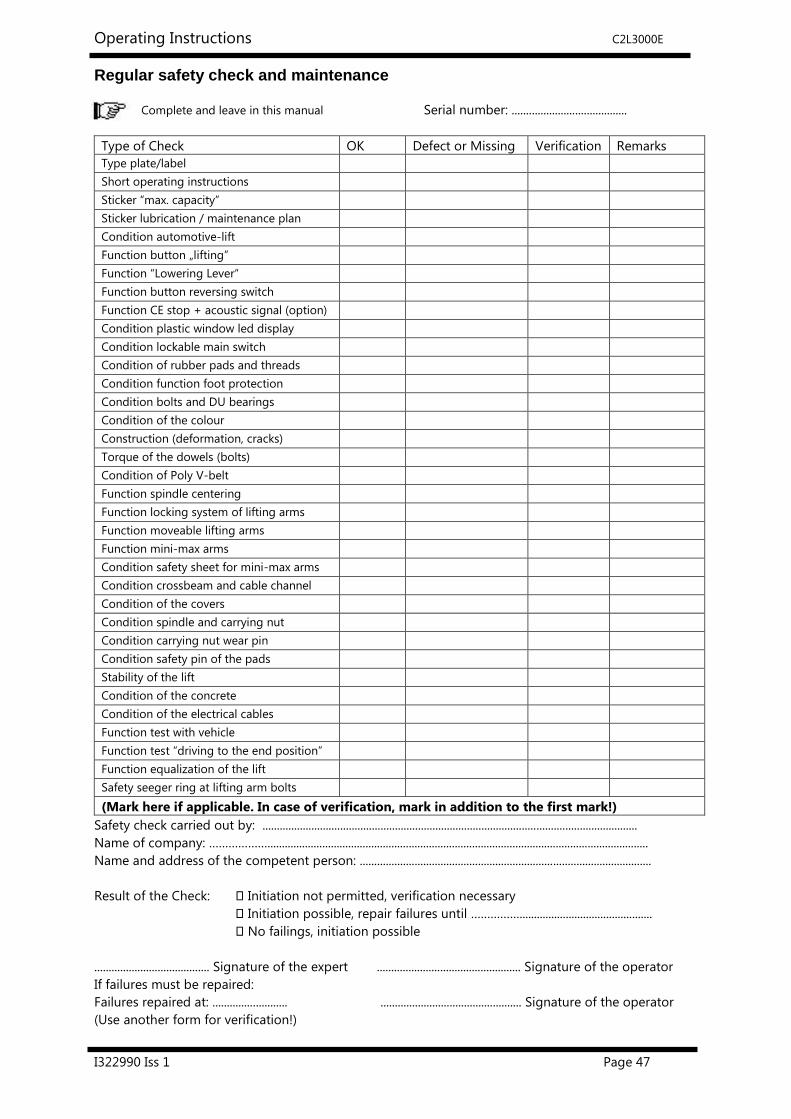
Regular safety check and maintenance
Complete and leave in this manual Serial number: ........................................
Type of Check OK Defect or Missing Verification Remarks
Type plate/label
Short operating instructions
Sticker “max. capacity”
Sticker lubrication / maintenance plan
Condition automotive-lift
Function button „lifting”
Function “Lowering Lever“
Function button reversing switch
Function CE stop + acoustic signal (option)
Condition plastic window led display
Condition lockable main switch
Condition of rubber pads and threads
Condition function foot protection
Condition bolts and DU bearings
Condition of the colour
Construction (deformation, cracks)
Torque of the dowels (bolts)
Condition of Poly V-belt
Function spindle centering
Function locking system of lifting arms
Function moveable lifting arms
Function mini-max arms
Condition safety sheet for mini-max arms
Condition crossbeam and cable channel
Condition of the covers
Condition spindle and carrying nut
Condition carrying nut wear pin
Condition safety pin of the pads
Stability of the lift
Condition of the concrete
Condition of the electrical cables
Function test with vehicle
Function test “driving to the end position”
Function equalization of the lift
Safety seeger ring at lifting arm bolts
(Mark here if applicable. In case of verification, mark in addition to the first mark!)
Safety check carried out by: ..................................................................................................................................
Name of company: ………………....................................................................................................................................
Name and address of the competent person: .....................................................................................................
Result of the Check: � Initiation not permitted, verification necessary
� Initiation possible, repair failures until ……………..............................................
� No failings, initiation possible
........................................ Signature of the expert .................................................. Signature of the operator
If failures must be repaired:
Failures repaired at: .......................... ................................................. Signature of the operator
(Use another form for verification!)

Operating Instructions C2L3000E
I322990 Iss 1 Page 48
Regular safety check and maintenance
Complete and leave in this manual Serial number: ........................................
Type of Check OK Defect or Missing Verification Remarks
Type plate/label
Short operating instructions
Sticker “max. capacity”
Sticker lubrication / maintenance plan
Condition automotive-lift
Function button „lifting”
Function “Lowering Lever“
Function button reversing switch
Function CE stop + acoustic signal (option)
Condition plastic window led display
Condition lockable main switch
Condition of rubber pads and threads
Condition function foot protection
Condition bolts and DU bearings
Condition of the colour
Construction (deformation, cracks)
Torque of the dowels (bolts)
Condition of Poly V-belt
Function spindle centering
Function locking system of lifting arms
Function moveable lifting arms
Function mini-max arms
Condition safety sheet for mini-max arms
Condition crossbeam and cable channel
Condition of the covers
Condition spindle and carrying nut
Condition carrying nut wear pin
Condition safety pin of the pads
Stability of the lift
Condition of the concrete
Condition of the electrical cables
Function test with vehicle
Function test “driving to the end position”
Function equalization of the lift
Safety seeger ring at lifting arm bolts
(Mark here if applicable. In case of verification, mark in addition to the first mark!)
Safety check carried out by: ..................................................................................................................................
Name of company: ………………....................................................................................................................................
Name and address of the competent person: .....................................................................................................
Result of the Check: � Initiation not permitted, verification necessary
� Initiation possible, repair failures until ……………..............................................
� No failings, initiation possible
........................................ Signature of the expert .................................................. Signature of the operator
If failures must be repaired:
Failures repaired at: .......................... ................................................. Signature of the operator
(Use another form for verification!)

Operating Instructions C2L3000E
I322990 Iss 1 Page 49
Regular safety check and maintenance
Complete and leave in this manual Serial number: ........................................
Type of Check OK Defect or Missing Verification Remarks
Type plate/label
Short operating instructions
Sticker “max. capacity”
Sticker lubrication / maintenance plan
Condition automotive-lift
Function button „lifting”
Function “Lowering Lever“
Function button reversing switch
Function CE stop + acoustic signal (option)
Condition plastic window led display
Condition lockable main switch
Condition of rubber pads and threads
Condition function foot protection
Condition bolts and DU bearings
Condition of the colour
Construction (deformation, cracks)
Torque of the dowels (bolts)
Condition of Poly V-belt
Function spindle centering
Function locking system of lifting arms
Function moveable lifting arms
Function mini-max arms
Condition safety sheet for mini-max arms
Condition crossbeam and cable channel
Condition of the covers
Condition spindle and carrying nut
Condition carrying nut wear pin
Condition safety pin of the pads
Stability of the lift
Condition of the concrete
Condition of the electrical cables
Function test with vehicle
Function test “driving to the end position”
Function equalization of the lift
Safety seeger ring at lifting arm bolts
(Mark here if applicable. In case of verification, mark in addition to the first mark!)
Safety check carried out by: ..................................................................................................................................
Name of company: ………………....................................................................................................................................
Name and address of the competent person: .....................................................................................................
Result of the Check: � Initiation not permitted, verification necessary
� Initiation possible, repair failures until ……………..............................................
� No failings, initiation possible
........................................ Signature of the expert .................................................. Signature of the operator
If failures must be repaired:
Failures repaired at: .......................... ................................................. Signature of the operator
(Use another form for verification!)

Operating Instructions C2L3000E
I322990 Iss 1 Page 50
12.7 Extraordinary safety check
Complete and leave in this manual Serial number: ........................................
Type of Check OK Defect or Missing Verification Remarks
Type plate/label
Short operating instructions
Sticker “max. capacity”
Sticker lubrication / maintenance plan
Condition automotive-lift
Function button „lifting”
Function “Lowering Lever“
Function button reversing switch
Function CE stop + acoustic signal (option)
Condition plastic window led display
Condition lockable main switch
Condition of rubber pads and threads
Condition function foot protection
Condition bolts and DU bearings
Condition of the colour
Construction (deformation, cracks)
Torque of the dowels (bolts)
Condition of Poly V-belt
Function spindle centering
Function locking system of lifting arms
Function moveable lifting arms
Function mini-max arms
Condition safety sheet for mini-max arms
Condition crossbeam and cable channel
Condition of the covers
Condition spindle and carrying nut
Condition carrying nut wear pin
Condition safety pin of the pads
Stability of the lift
Condition of the concrete
Condition of the electrical cables
Function test with vehicle
Function test “driving to the end position”
Function equalization of the lift
Safety seeger ring at lifting arm bolts
(Mark here if applicable. In case of verification, mark in addition to the first mark!)
Safety check carried out by: ..................................................................................................................................
Name of company: ………………....................................................................................................................................
Name and address of the competent person: .....................................................................................................
Result of the Check: � Initiation not permitted, verification necessary
� Initiation possible, repair failures until ……………..............................................
� No failings, initiation possible
........................................ Signature of the expert .................................................. Signature of the operator
If failures must be repaired:
Failures repaired at: .......................... ................................................. Signature of the operator
(Use another form for verification!)

Operating Instructions C2L3000E
I322990 Iss 1 Page 51
13 AFTER SALES SERVICE
Apart from the routine maintenance and adjustments stipulated in this manual the equipment must
not be tampered with in any way. All further servicing must be carried out only by an engineer from
an Authorised Agent. Failure to observe these conditions will invalidate the Guarantee.
13.1 On-Site Service / Overhaul / Spare Parts
If you require a Service Engineer to attend ON SITE, either due to an equipment fault, or for
machine calibration, or if the equipment covered by this manual requires to be sent back for
factory overhaul, or if you need spare parts, please contact our Product Support Department
Outside UK mainland
Service for export customers are provided by the agent from whom your equipment was
purchased.
UK After-Sales Service
Call Crypton Support for details of local service agents.
Technical Information
Crypton also provide information and contracts covering:
Car Data, Fault Code Information, Diagnostic Information, Software Support Contracts,
Software Updates & Accessories.
13.2 CONTACT DETAILS
Contact UK Sales on 0844 665 7613
Email [email protected]
Contact Support – 0844 665 7610
Support Fax - UK 0844 665 7604
Email [email protected]
Continental Automotive Trading UK Ltd
36 Gravelly Industrial Park
Birmingham B24 8TA
United Kingdom
www.cryptontechnology.com
Crypton - A Brand of the Continental Corporation
E & O E. The Company reserves the right to introduce improvements in design or specification without prior notice.
The sale of this product is subject to our standard terms, conditions and relevant product warranty


![U.S. ACCESS BOARD TECHNICAL GUIDE Elevators and Platform Lifts · Chapter 4: Accessible Routes Elevators and Platform Lifts 2 Elevator Landing Requirements [§407.2] Hall Signals](https://static.fdocuments.us/doc/165x107/5eb55d8cd642b900bf1a9e5b/us-access-board-technical-guide-elevators-and-platform-chapter-4-accessible-routes.jpg)