Cryogenic Recovery of VOC Emissions - InfoHouseinfohouse.p2ric.org/ref/29/28031.pdf · CRYOGENIC...
20
CRYOGENIC RECOVERY OF VOC EMISSIONS G. T. Sameshima J. D. Eisenwasser Liquid Carbonic Industries Corporation Chicago, IL . Presented at TheU.S. Department of Energy, Office of Industrial Technologies Industrial Solvent Recycling Conference May 24,1991 San Diego, California 297
-
Upload
truongkiet -
Category
Documents
-
view
224 -
download
3
Transcript of Cryogenic Recovery of VOC Emissions - InfoHouseinfohouse.p2ric.org/ref/29/28031.pdf · CRYOGENIC...

CRYOGENIC RECOVERY OF VOC EMISSIONS
G. T. Sameshima
J. D. Eisenwasser
Liquid Carbonic Industries Corporation
Chicago, IL
. Presented at TheU.S. Department of Energy, Office of Industrial Technologies
Industrial Solvent Recycling Conference
May 24,1991 San Diego, California
297

troduction A new method of condensing vapors using liquid nitrogen (LN2) as a refrigerant has been developed to reduce emissions of potentially dangerous Volatile Organic Compounds (VOCs) used in many industrial processes. The need to reduce these emissions is increasing due to stricter emission standards and the public's demands for a cleaner environment.
Current emission control processes include: adsorption (carbon beds), incineration and condensation. Regenerative adsorption equipment can be expensive, extremely large and must be desorbed to recover VOCs. Incinemion equipment destroys the VOCs but can result in secondary pollutants. Conventional mechanical condensing equipment can comprise multiple compressors, pumps and heat exchangers which can be difficult to maintain. Liquid Carbonic Industries Corporation has developed a condensing technique that uses the natural refrigerating ability of LN2 to condense VOCs.
Condensation Condensation is the process where by a substance experiences a change of phase from a gas to a liquid. Two ways of triggering this process are compression and temperature reduction. The figure below shows the effect that temperature has on the maximum concentration of a vapor such as methyl ethyl ketone (MEK).
Maximum Concentration at 1 Atmosphere
-125 -100 -75 -50 -25 0 25 50 75 100 125 150 175 Temperature ( O F )
- Figure 1. Maximum Concentration of MEK at 1 Atmosphere
LN2 is a cryogenic fluid (-320°F @ 1 atmosphere) that is produced from air. In fact, close to 80% of the air we breathe is gaseous nitrogen. LN2 can be used as a refrigerant to lower the temperature and condense the vapors of a vapor laden gas stream.
I I I I 1
1 1 I i
1 j
Liquid Carbonic Industries Corporation Cryogenic Recovery of VOC Emissions
298

Crvoggnic C o n d e w T e c h n b There are several techniques for using LN2 to lower the temperature of a gas flow. Three common methods are described below.
LN2
GN2 Exhaust Exhaust
LN2
H/X H/X A H/X Fluid
4 I f--
L :ontrot Valve e - I v Pump - Condensate
Figure 3. Indirect Contact - Dual Heat Exchanger
In another indirect method, LN2 is used to cool a heat transfer fluid in a heat exchanger. The heat transfer fluid is then pumped to a second heat exchanger that cools and condenses the vapors to be recovered. The capital cost, maintenance cost and overall complexity limit this method's usefulness.
Liquid Carbonic Industries Corporation Cryogenic Recovery of VOC Emissions
299

Exhaust
Vapor Laden Gas Flow
Condhsate Figure 4. Direct Contact
The direct contact method as its name implies, allows the LN2 to contact the condensible vapors. This results in very fast heat transfer in a simple system with very few moving parts. This method was chosen by Liquid Carbonic as the most practical due to its simplicity, cost, and ease of operation. Mathematical models showed that the direct contact method could be an excellent emission reduction device as well as economically attractive.
The mathematical models for the vapor recovery system were based on numerous thermodynamic equations as well as Wagner's Equation which correlates the vapor pressure of a chemical to its temperature.
I
ln(Pup/pc) = (l-x)-l[ (VP A)x + (VP B)x1.5 + (VP C)x3 + (VP D)x6]
T 1 - - TC Vapor Pressure critical pressure
- - where X
PC Tc = CriticalTemperature T = Temperature, VP A, VP B, VP C, and VP D are experimental constants
- p.p - - -
Application of Wagner's Equation and the Ideal Gas Law produces a description of the vapor laden gas flow. By applying several common thermodynamic equations, the amount of LN2 required for recovery can be established. Once this is done, a mathematical model of the vapor recovery system is easily constructed. Three basic thermodynamic equations are used. They are:
i I 1
I i I I 1 I I i I I i i 1
Liquid Carbonic Industries Corporation Cryogenic Recovery of VOC Emissions
300

‘1 1 3 1 -
:-I i.. 7 3 3 n 3 II :I :I :1 3 Li
4 I] I
where: Q = Energy,inBtu M = Mass in, Ibm Cpv = Specific Heat as Gas, in Btu
Cpl = Specific Heat as Liquid, in Btu AT = Change in Temperature, in OF
BN Heat of Vaporization, in
A consequence of these mathematical models was the realization that higher vapor concentrations result in more economical recovery of condensible vapors. This can be explained by examining how the LN2 is used to condense the vapors. The LN2 is condensing the targeted vapor as well as cooling the gas in which the condensible vapor is carried. If the vapor concentration is high, a ,greater percentage of the LN2’s thermal energy is used to condense the vapors and a lesser percentage is used to cool the carrier gas.
The diagram below illustrates the effect vapor concentration has on the theoretical amount of LN2 required to condense one pound of MEK for otherwise identical process conditions.
Ibs of LN2 per Ib MEK Recovered
30 rz 20
10
0 - 1% 5% 10% 20% 30%
Vapor Concentration Figure 5. Concentration Effect on LN2 Usage
A difference-between the direct and indirect methods is the dilution effect. The dilution effect results from the mixing of the LN2 with the process gas stream which increases the volumetric flow rate from the vapor recovery system. Since the operating temperature limits the exhaust concentration, the direct contact vapor recovery system theoretically emits more vapors due to its higher exhaust flow rate than an indirect contact system. However, the difference in performance is very small. Figure 6 compares the performance using the direct and indirect contact methods for identical process streams.
Liquid Carbonic Industries Corporation Cryogenic Recovery of VOC Emissions
301
Emission Reduction
loo%%
I I
-90°F -1 00°F -1 1 0°F , Operatinn Temperature
1 I 81 Direct Indirect I I
Figure 6. C o m p a r i s o n i i Reduction for Direc t versus Indirect Methods
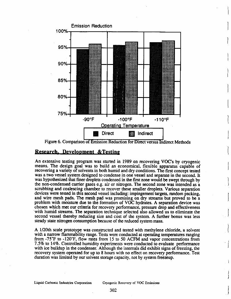
An extensive testing program was started in 1989 on recovering VOC's by cryogenic means. The design goal was to build an economical, flexible apparatus capable of recovering a variety of solvents in both humid and dry conditions. The first concept tested was a two vessel system designed to condense in one vessel and separate in the second. It was hypothesized that f i e r droplets condensed in the first zone would be swept through by the non-condensed carrier gases e.g. air or nitrogen. The second zone was intended as a scrubbing and coalescing chamber to recover these smaller droplets. Various separation devices were tested in this second vessel including: impingement targets, random packing, and wire mesh pads. The mesh pad was promising on dry streams but proved to be a problem with moisture due to the formation of VOC hydrates. A separation device was chosen which met our criteria for recovery performance, pressure drop and effectiveness with humid streams. The separation technique selected also allowed us to eliminate the second vessel thereby reducing size and cost of the system. A further bonus was less steady state nitrogen consumption because of the reduced system mass.
A 1/20th scale prototype was constructed and tested with methylene chloride, a solvent with a narrow flammability range. Tests were conducted at operating temperatures ranging from -75'F to -120"F, flow rates from 15 to 50 ACFM and vapor concentrations from 7.5% to 14%. Controlled humidity experiments were conducted to evaluate performance with ice buildup in the condenser. Although the internals did exhibit signs of freezing, the recovery system operated for up to 8 hours with no effect on recovery performance. Test duration was limited by our solvent storage capacity, not by system freezeup.
i I 1
i i i I I I I
i ! i i i
i I
Liquid Carbonic Industries Corporation Cryogenic Recovery of VOC Emissions
302

hoduction VaDor Recoverv Svstem As a result of the encouraging test results, it was decided to build a commercial size vapor recovery system. The drawing below is a schematic of this system.
I -Exhaust
LN2 Condenser
Figure 7. Schematic of a Vapor Recovery System
In many cases, it is prudent to use the exhaust gas of the vapor recovery system to precool the vapor laden gas entering the system. This makes the most efficient use of the thermal energy of liquid nitrogen. The drawing below is a schematic of a vapor recovery system with a recuperator.
- LN2
1
Secondary Separator
Exhaust
-4 Condensate
Vapor' Laden Gas Flow
Figure 8. Schematic of a Vapor Recovery System with Recuperator
Liquid Carbonic Industries Corporation Cryogenic Recovery of VOC Emissions
303

A manufacturer of colored aquarium gravel in New Jersey uses methylene chloride as part of his coatings process. Previous attempts at recovering the methylene chloride vapors using compression and mechanical refrigeration had proved ineffective at meeting newer New Jersey EPA regulations. Carbon beds were looked at but were found to be too expensive to purchase, too large and required additional labor. Liquid Carbonic suggested a cryogenic condensation vapor recovery system with a recuperator. The vapor recovery system was installed and started up in April of 1990. The process data for the flow into the vapor recovery system is given below.
Temperam
I I 1
~ 1 2 0 ° F I I Flow Rate ~ 1 5 0 ACFM I
Pressure 0.1 psig 0.7 psig
100% go%-----
80%--
60%
40%
30%-- 20% lo%---
70%
50%
0%
I ! Methylene Chloride Concentration =11% I
-- -- -..-- --
--
I. ' - .
I Methylene Chloride Throughput I ~3.50 lb/min I Below is a graph showing how the concentration of methylene chloride can be reduced by cooling and condensing the methylene chloride.
II Concentration at 1 Atmosphere
1 ' . " 1 ~ " ' 1 . " . 1
25 -100 -75 -50 -25 0 25 50 75 100 1 Temperature O F
I-------- Maximum Concentration - Process Concentration I
I
!5
Figure 9. Vapor Recovery Process Profile
The above graph shows that the methylene chloride level in the gas flow is constant until the gas flow temperature is reduced to approximately 13°F. At this temperature the methylene chloride starts to condense into a liquid. As the temperature continues to
Liquid Carbonic Industries Corporation Cryogenic Recovery of VOC Emissions
304

decrease the gas flow's ability to hold methylene chloride in its vapor phase is decreased. The methylene chloride is forced to become a liquid. Operating at -120'F. the vapor recovery system has been found to reduce emissions by as much as 98%. The table below shows the operating data of the recovery system.
Operating Temperature -120°F
Emission Reduction (mass) =98%
LN2 Used Vapor Recoveredwi* Recupmf
3.02
* Carbon Bed System includes: two 8' diameter adsorber vessels, two fans, control panel, 11,200 Ibs activated carbon, ductwork & air filter, valves, precooler, boiler, cooling tower, chiller, air compressor, product storage tank, transfer pump, hydrocarbon analyzer, and steam stripper.
- -
Liquid Carbonic VRS
A dual vapor recovery system is being built to operate 24 hours a day 7 days a week to recover a monomer in a chemical plant, The two vapor recovery systems will share a common recuperator and electrical controls. Two vapor recovery systems are needed to enable one unit to defrost while the other is in use. Although freezing of the monomer is unlikely, two units will guarantee that the monomer emission is controlled 24 hours a day.
Carbon Bed
System*
Liquid Carbonic Industries Corporation Cryogenic Recovery of VOC Emissions
305
Capital Cost $75,000 $250,000

Tests are being conducted to develop an indirect contact LN2 vapor recovery system. Although this method is more complex than the direct contact method, indirect contact's major advantage is the availability of clean gaseous N2 as a byproduct of the process. The N2 could then be used for inerting, blanketing or sparging.
Several methods of increasing the VOC concentration going into the vapor recovery system are being explored as well. As mentioned earlier, higher VOC concentrations result in lower LN2 consumption and lower operating costs.
Conclusion Cryogenic condensation of VOCs using LN2 has been shown to be an economical method of reducing VOC emissions. In the past, people had assumed that this method was not economically competitive with more traditional emission control devices due to its perceived higher operating costs, i.e. LN2 costs. However, the simplicity of the vapor recovery system reduces the initial capital expense and maintenance costs. Also, the Liquid Carbonic vapor recovery system has the ability to handle a wide range of flows with little or no modifications. The recent emphasis on the environment by both the government and the public has made pollution control devices a must for doing business in the 1990s. The Liquid Carbonic vapor recovery system can economically reduce VOC emissions by using a refrigerant that is both safe and natural.
Liquid Carbonic Industries Corporation Cryogenic Recovery of VOC Emissions
306

Liquid Carbonic Industries Corporation
R. J. Spencer Manager of Cryogenic Applications
Condensation
307
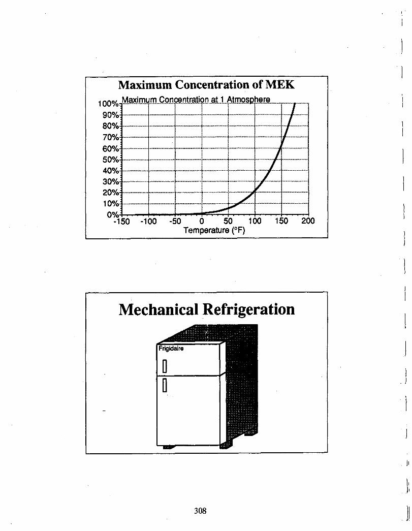
Maximum Concentration of MEK
Temperature (OF)
Mechanical Refrigeration
i I I I I i I
I 1 J i
I I
308 i t JI II

GN2 Exhaust Exhaust
H/X
Va rLaden g. Flow
Valve Condknsate
Indirect Contact Method Single Heat Exchanger
Indirect Method I Dual Heat Exchanger
H/X
309

Direct Contact Exhaust
a rLaden Gs Flow
I Valve
+ Condensate
1 Effect of Vapor Concentration 25
20
15
10
5
0
........................................................................................................................................
1% 5% 10% 20% 30% Vapor Concentration
I
I I I I i I I
I I I
I
I I
i
3 10

n n
Liquid Carbonic VRS Va rLaden Es Fbw-
Secondary Sewator
Exhaust
Condensate
Liquid Carbonic VRS with Recuperator
I-K Control
as Fbw
Condensate
311

Economics
Case Study Data
Flow Rate Temperature
pressure Methylene Chloride Concentration Methylene Chloride Throughput
150 ACFM 120°F
I 0.25 psig 11%
3.50 lb/min I ~~ ~~ ~
Operating Temperature Emission Reduction r - Cryogen Consumption Ratio
-120°F 98%
3.02: 1.00
i I 1 I I I I 1 I I
I I i
I 1
1 I
3 12

3 1 3
3 3 3 3 :1
3
Case Study Process Profile Vapor Concentration at 1 Atmosphere 1100%3 i i 1 i
-1 50 -1 00 -50 0 50 100 150 I Temperature I - Maximum Concentration - Process Concentration I
Economic Comparison Liquid CHrbOnic Carbon
VRS Bed ~- ~~~ ~ ~
Capital Cost: Installation Cost Amortized Capital & Installation Costa
$er month over 10 years @ 10% per annum:
Operating Costs, per month: LN2 Tank Service Fee, per month: LN2 Cost, per month @ 4.5e / lb: Solvent Recovered, per month:
Cost per Pound of Solvent Recovered
~~~ ~
$75,000 $5,500
$1,100
$1,200 $5,000 36,800 lbs
2051
~
$250,000 $24,000
$3,600 $5,000
36,000 lbs
Nsl
3 13

Case Study #2 Process Profile
-225 -200 -175 -150 -125 -100 -75 -50 -25 0 25 Temperature ( O F )
.A. .../. ......... Maximum Concentration - Process Concentration 1
Case Study #2 Economics Capital Cost $150,000 Installation Cost $10,000 Amortized Capital & Installation Cost,
per month over 10 years @ 10% per annum $2,110
LN2 Tank Service Fee, per month LN2 Cost, per month @ 4.5$ / lb Solvent Recovered, per month
Cost per Pound of Solvent Recovered
$1,800 $14,220 143,640 lbs
12.65
-
I !
3 14

1 :1
Conclusion Low Capital Cost High Concentration Vapor Flammable Vapors Intermittent Processes
Streams
Turn Up 1 Turn Down Capability Recovered Solvent No Secondary Waste
315

1
i