Cryogenic LNG Expanders Reduce Natural Gas Liquefaction · PDF fileCryogenic LNG Expanders...
36
Cryogenic LNG Expanders Reduce Natural Gas Liquefaction Costs Hans E. Kimmel Executive Director R&D [email protected] Ebara International Corporation Sparks, Nevada, USA
Transcript of Cryogenic LNG Expanders Reduce Natural Gas Liquefaction · PDF fileCryogenic LNG Expanders...
Cryogenic LNG Expanders Reduce Natural Gas Liquefaction Costs
Hans E. KimmelExecutive Director R&D [email protected]
Ebara International CorporationSparks, Nevada, USA
Company Profile
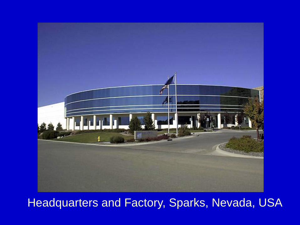
Headquarters and Factory, Sparks, Nevada, USA
EBARA International CorporationCryodynamics Division
Company Profile
•Established in 1973•Manufacturer of custom engineered liquefied gas pumps and expanders•Located in Sparks, Nevada, USA•Division of Ebara Corporation of Japan•5000 M2 factory with a modern, dedicatedliquefied gas test facility
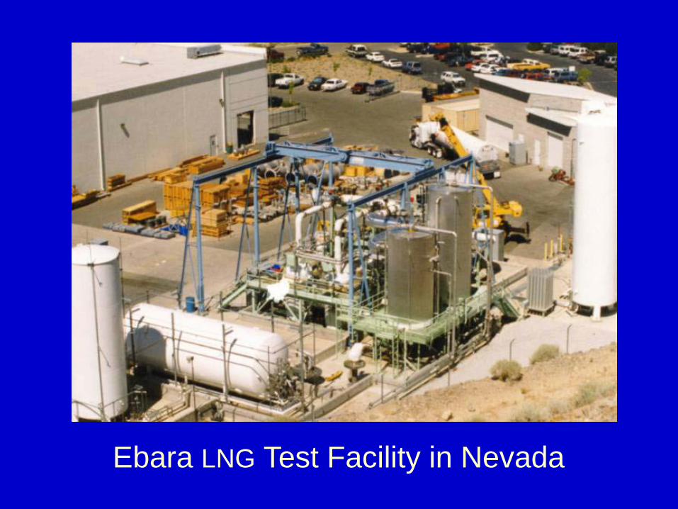
Ebara LNG Test Facility in Nevada
The liquefaction of Natural Gas requires a significant amount
of energy for the refrigeration process
Cryogenic LNG Expanders reduce this amount of energy
by replacing the throttling Joule-Thomson Valve
with a power generating Expansion Turbine.
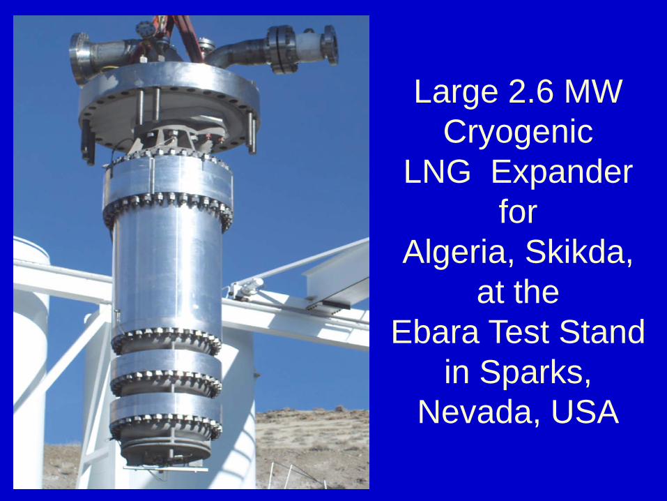
Large 2.6 MWCryogenic
LNG Expanderfor
Algeria, Skikda, at the
Ebara Test Stand in Sparks,
Nevada, USA
In existing older LNG plants with a liquefaction capacity
of 100% the pressurized condensed LNG is passed across a Joule-Thomson
Valve reducing the pressure to storage conditions
The pressure reduction across the J-T valve
produces 10% undesirable LNG vapour and only 90% of
the liquid LNG is delivered to the storage tank
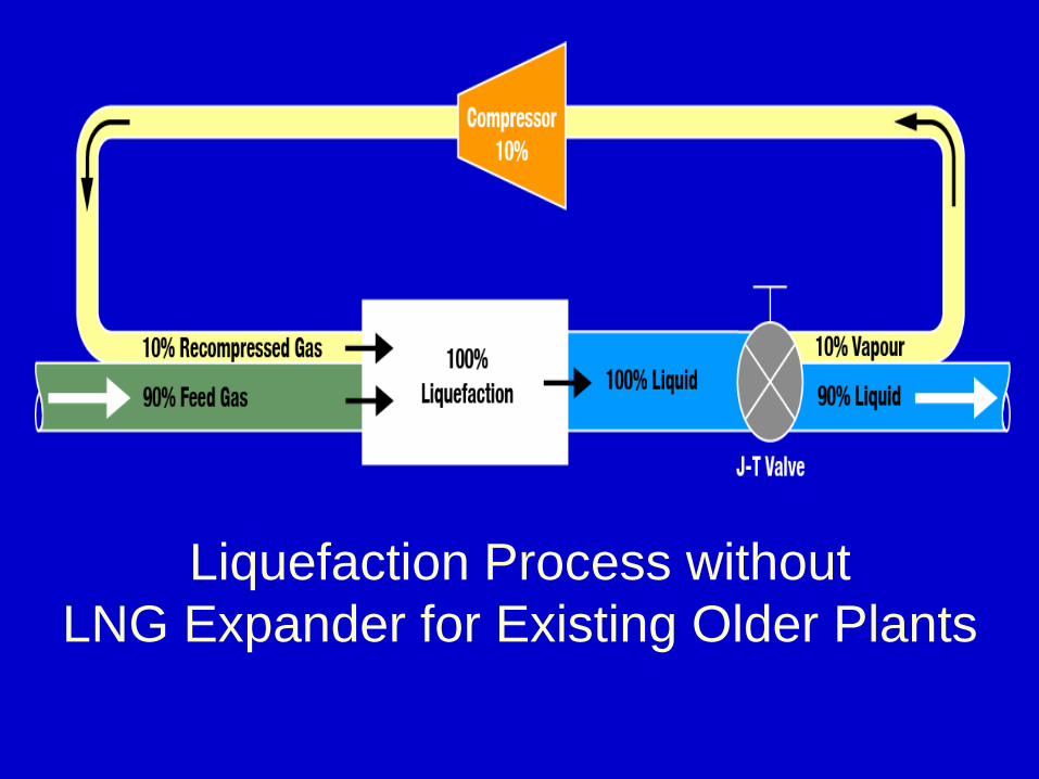
Liquefaction Process without LNG Expander for Existing Older Plants
By replacing the J-T valve with a cryogenic LNG expander the amount of undesirable
LNG vapour is reduced from 10% to only 5%, and in
existing older plants 95% of the liquid LNG is delivered
to the storage tank
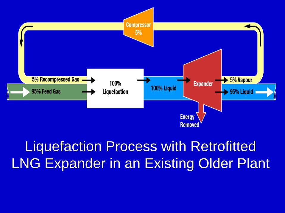
Liquefaction Process with RetrofittedLNG Expander in an Existing Older Plant
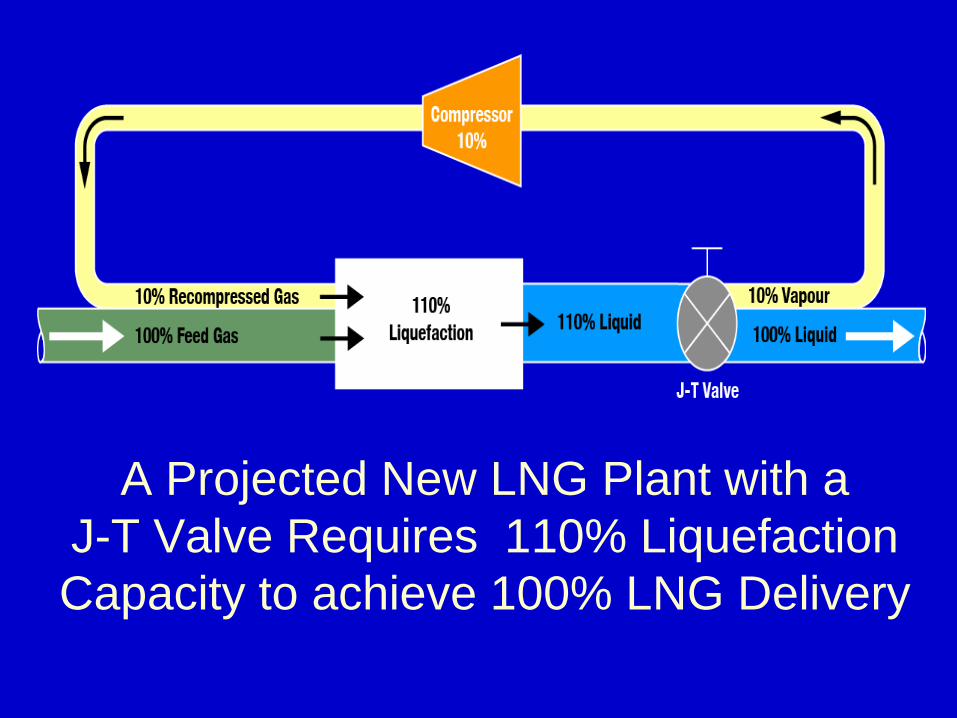
A Projected New LNG Plant with aJ-T Valve Requires 110% Liquefaction Capacity to achieve 100% LNG Delivery
If in a projected new plant the LNG pressure reduction occurs across a cryogenic LNG Expander, the entire liquefaction plant has to be
sized only for 105% capacity for a delivery of 100% LNG
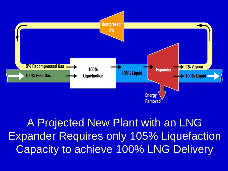
A Projected New Plant with an LNG Expander Requires only 105% Liquefaction
Capacity to achieve 100% LNG Delivery
Cryogenic Expanders remove
Pressure Energy from the LNG Stream
and convert it into Electrical Power
The overall efficiency of the liquefaction process is
inversely proportional to the Specific Power Consumption,
which is defined as the ratio of the
Total Power Consumption over the
Total LNG Production
The LNG Expander typically increases the LNG Production
between 3 – 5 % and decreases the Total Power Consumption
by the same percentage of 3-5%
By adding 3-5% to the LNG Production
and subtracting 3-5% from the Total Power Consumption,
the Specific Power Consumption reduces by 6-10%,
and the Overall Plant Efficiency increases by 6-10%
Cryogenic LNG Expanders are field proven for 15 years
They are installed and successfully operating in
most LNG liquefaction plants since 1996 until today,
and are also projected for installation in future plants
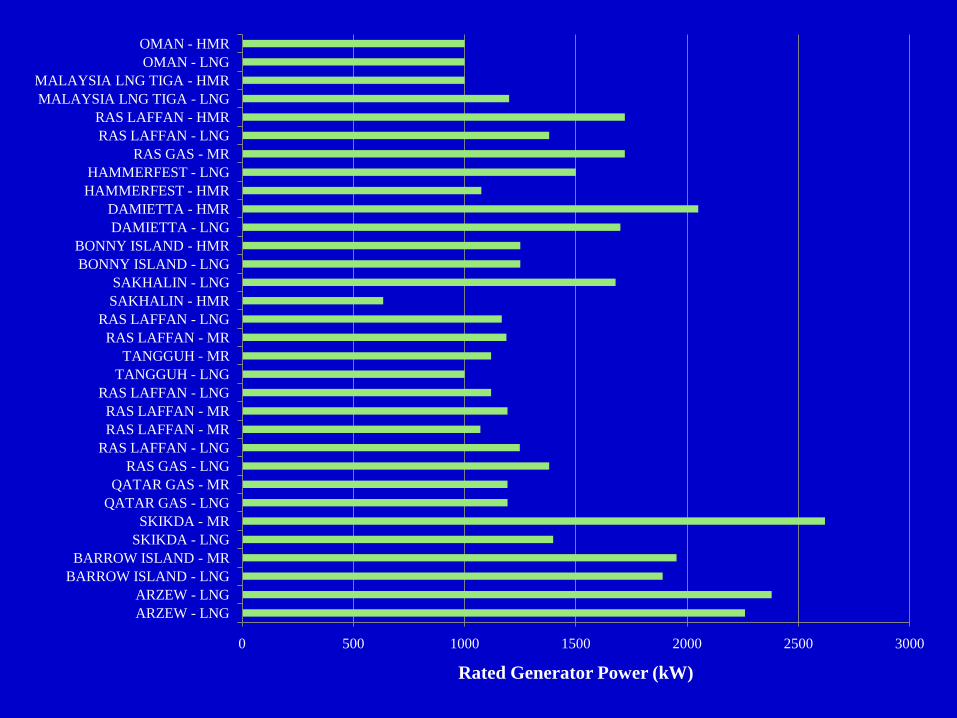
0 500 1000 1500 2000 2500 3000
ARZEW - LNGARZEW - LNG
BARROW ISLAND - LNGBARROW ISLAND - MR
SKIKDA - LNGSKIKDA - MR
QATAR GAS - LNGQATAR GAS - MR
RAS GAS - LNGRAS LAFFAN - LNGRAS LAFFAN - MRRAS LAFFAN - MR
RAS LAFFAN - LNGTANGGUH - LNGTANGGUH - MR
RAS LAFFAN - MRRAS LAFFAN - LNG
SAKHALIN - HMRSAKHALIN - LNG
BONNY ISLAND - LNGBONNY ISLAND - HMR
DAMIETTA - LNGDAMIETTA - HMR
HAMMERFEST - HMRHAMMERFEST - LNG
RAS GAS - MRRAS LAFFAN - LNGRAS LAFFAN - HMR
MALAYSIA LNG TIGA - LNGMALAYSIA LNG TIGA - HMR
OMAN - LNGOMAN - HMR
Rated Generator Power (kW)
The increase in LNG Production is directly proportional to the energy removed by
the LNG Expander.
1 kW of removed electrical power produces
60 tons/year of additional LNG
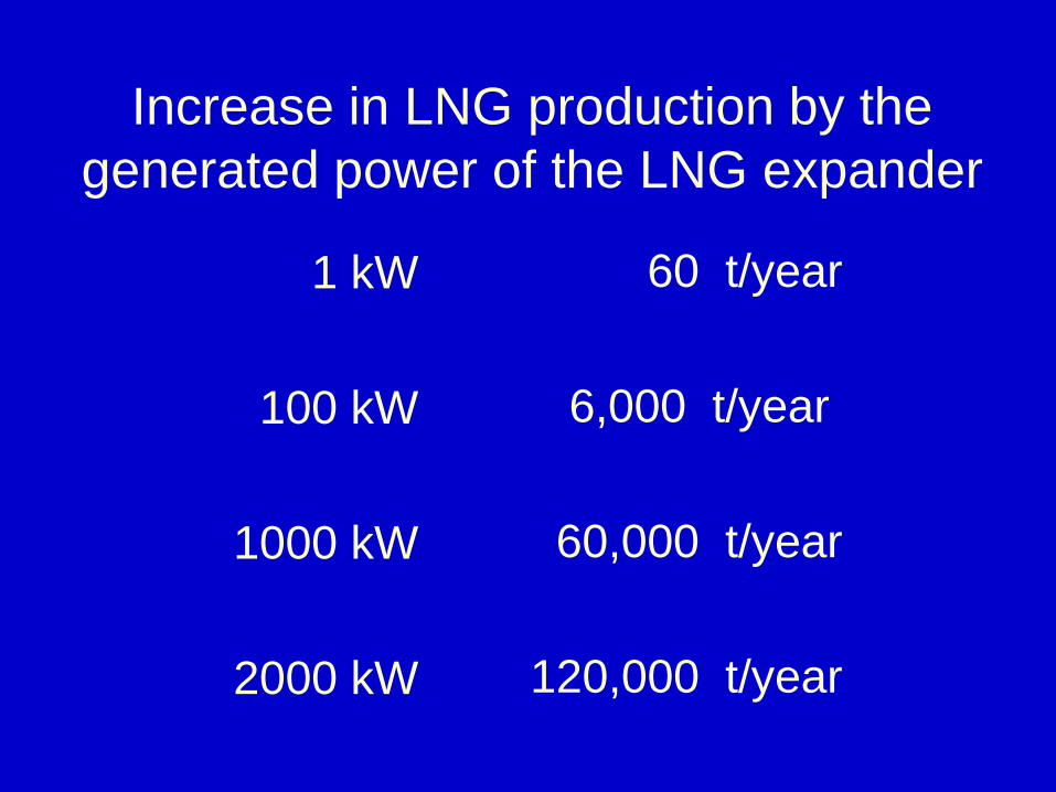
Increase in LNG production by the generated power of the LNG expander
1 kW
100 kW
1000 kW
2000 kW
60 t/year
6,000 t/year
60,000 t/year
120,000 t/year
An LNG Expander removing 2500 kW of electrical power
from the LNG stream produces 150,000 t/year
additional LNG for an annual revenue of 37.5 Mill US $
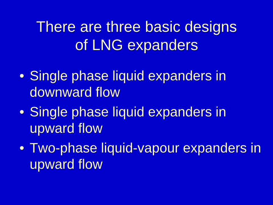
There are three basic designs of LNG expanders
• Single phase liquid expanders in downward flow
• Single phase liquid expanders in upward flow
• Two-phase liquid-vapour expanders in upward flow
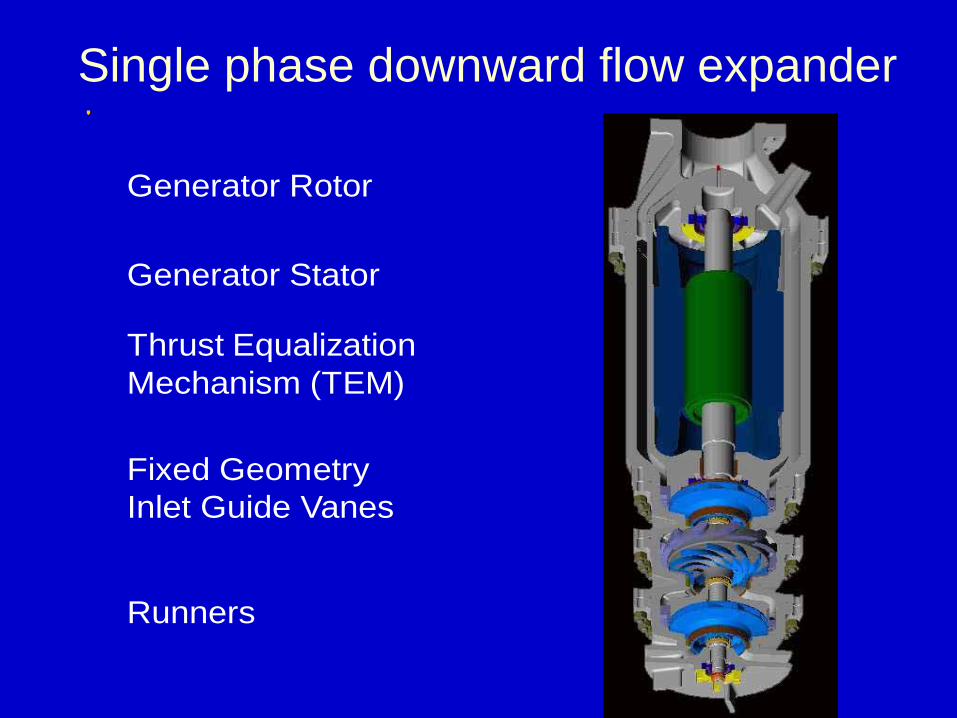
Single phase downward flow expander
Generator Rotor
Generator Stator
Thrust Equalization Mechanism (TEM)
Fixed Geometry Inlet Guide Vanes
Runners
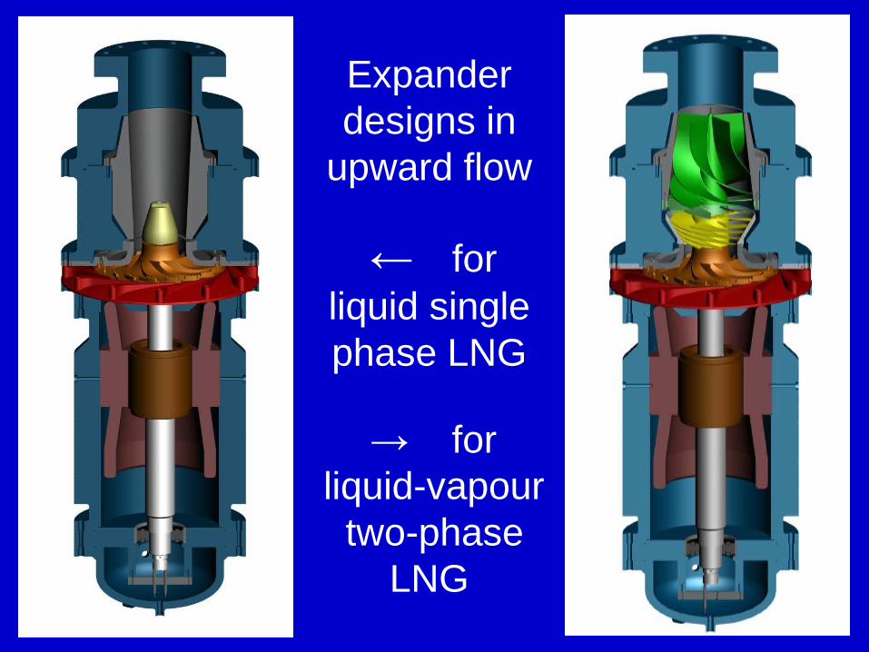
Expander designs in
upward flow
← for liquid singlephase LNG
→ forliquid-vapour
two-phase LNG
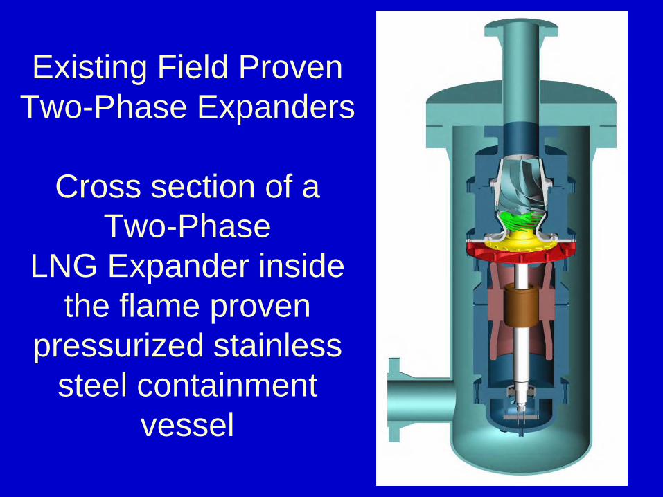
Existing Field Proven Two-Phase Expanders
Cross section of a Two-Phase
LNG Expander inside the flame proven
pressurized stainless steel containment
vessel
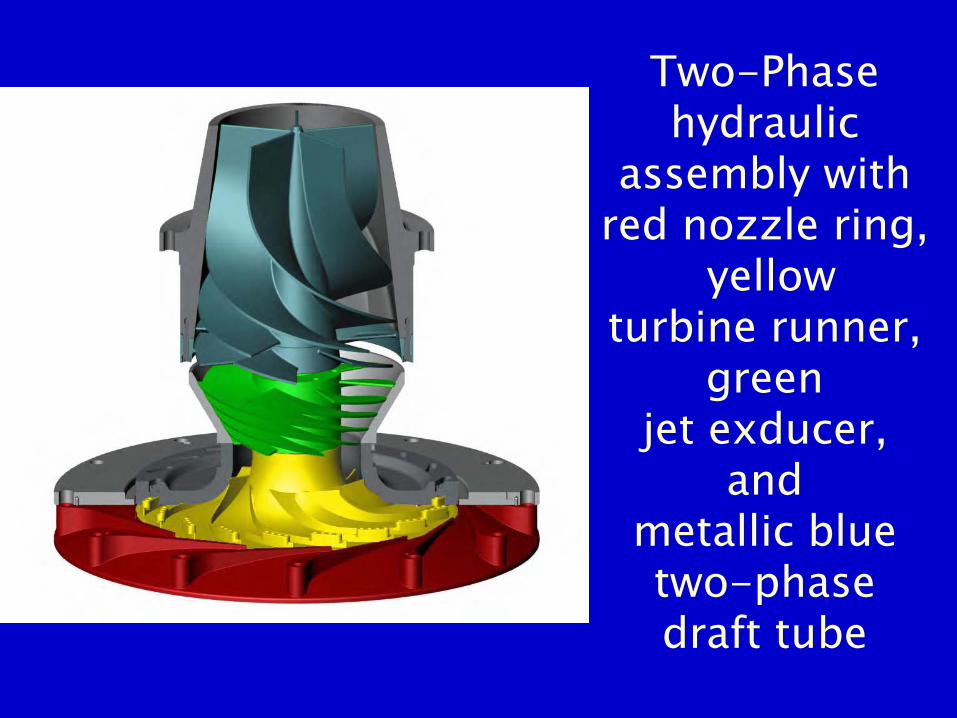
Two-Phasehydraulic
assembly with red nozzle ring,
yellow turbine runner,
green jet exducer,
and metallic blue two-phase draft tube
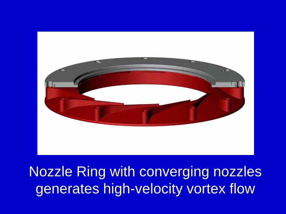
Nozzle Ring with converging nozzles generates high-velocity vortex flow
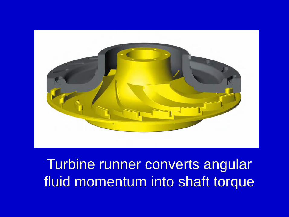
Turbine runner converts angular fluid momentum into shaft torque
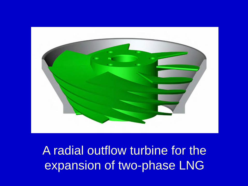
A radial outflow turbine for the expansion of two-phase LNG
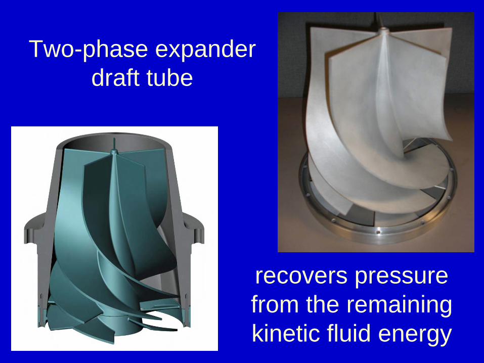
Two-phase expander draft tube
recovers pressure from the remaining kinetic fluid energy
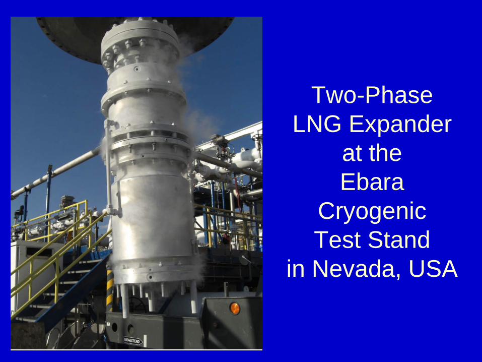
Two-Phase LNG Expander
at the Ebara
Cryogenic Test Stand
in Nevada, USA
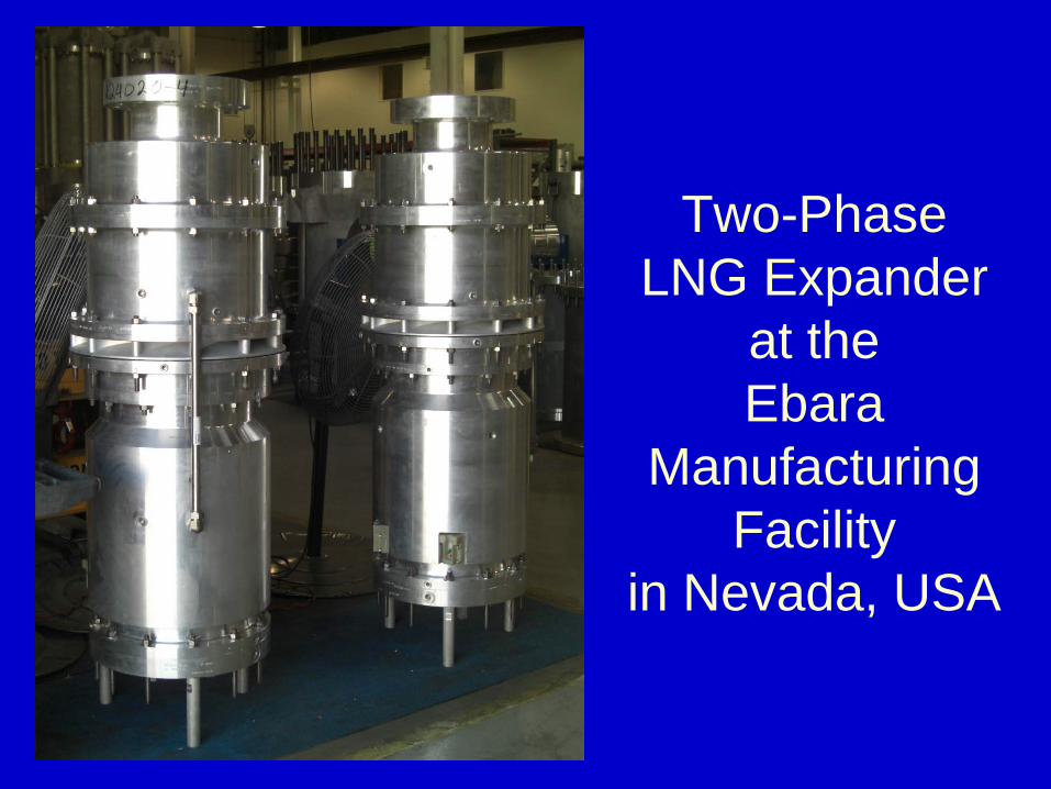
Two-Phase LNG Expander
at the Ebara
Manufacturing Facility
in Nevada, USA

Terima kasih atas perhatian Anda
Thank you for your attention
Hans E. Kimmel