CRUISE KIT NUMBERS 2008-2010 FORD F250/F350 2008 …2008-2010 FORD F250/F350 . 2008-2010 FORD...
12
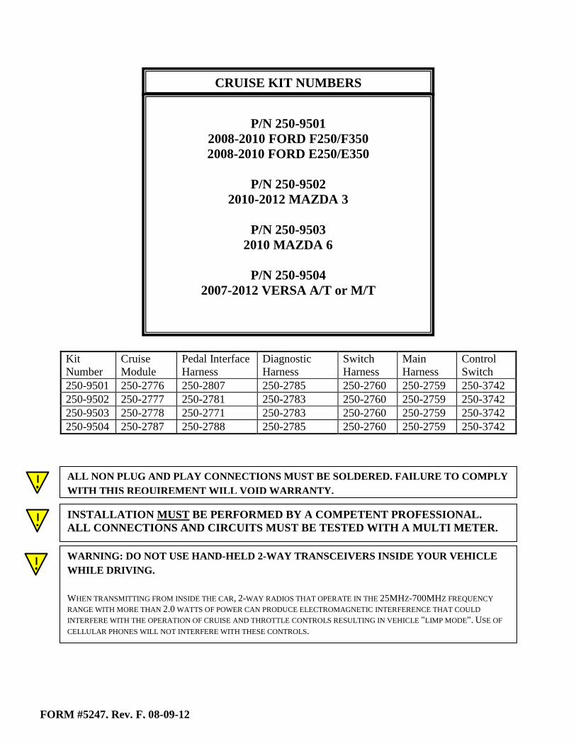
Kit Number Cruise Module Pedal Interface Harness Diagnostic Harness Switch Harness Main Harness Control Switch 250-9501 250-2776 250-2807 250-2785 250-2760 250-2759 250-3742 250-9502 250-2777 250-2781 250-2783 250-2760 250-2759 250-3742 250-9503 250-2778 250-2771 250-2783 250-2760 250-2759 250-3742 250-9504 250-2787 250-2788 250-2785 250-2760 250-2759 250-3742 FORM #5247, Rev. F, 08-09-12 CRUISE KIT NUMBERS P/N 250-9501 2008-2010 FORD F250/F350 2008-2010 FORD E250/E350 P/N 250-9502 2010-2012 MAZDA 3 P/N 250-9503 2010 MAZDA 6 P/N 250-9504 2007-2012 VERSA A/T or M/T ALL NON PLUG AND PLAY CONNECTIONS MUST BE SOLDERED. FAILURE TO COMPLY WITH THIS REQUIREMENT WILL VOID WARRANTY. INSTALLATION MUST BE PERFORMED BY A COMPETENT PROFESSIONAL. ALL CONNECTIONS AND CIRCUITS MUST BE TESTED WITH A MULTI METER. WARNING: DO NOT USE HAND-HELD 2-WAY TRANSCEIVERS INSIDE YOUR VEHICLE WHILE DRIVING. WHEN TRANSMITTING FROM INSIDE THE CAR, 2-WAY RADIOS THAT OPERATE IN THE 25MHZ-700MHZ FREQUENCY RANGE WITH MORE THAN 2.0 WATTS OF POWER CAN PRODUCE ELECTROMAGNETIC INTERFERENCE THAT COULD INTERFERE WITH THE OPERATION OF CRUISE AND THROTTLE CONTROLS RESULTING IN VEHICLE "LIMP MODE". USE OF CELLULAR PHONES WILL NOT INTERFERE WITH THESE CONTROLS.
Transcript of CRUISE KIT NUMBERS 2008-2010 FORD F250/F350 2008 …2008-2010 FORD F250/F350 . 2008-2010 FORD...
Kit Number
Cruise Module
Pedal Interface Harness
Diagnostic Harness
Switch Harness
Main Harness
Control Switch
250-9501 250-2776 250-2807 250-2785 250-2760 250-2759 250-3742 250-9502 250-2777 250-2781 250-2783 250-2760 250-2759 250-3742 250-9503 250-2778 250-2771 250-2783 250-2760 250-2759 250-3742 250-9504 250-2787 250-2788 250-2785 250-2760 250-2759 250-3742
FORM #5247, Rev. F, 08-09-12
CRUISE KIT NUMBERS
P/N 250-9501
2008-2010 FORD F250/F350 2008-2010 FORD E250/E350
P/N 250-9502
2010-2012 MAZDA 3
P/N 250-9503 2010 MAZDA 6
P/N 250-9504
2007-2012 VERSA A/T or M/T
ALL NON PLUG AND PLAY CONNECTIONS MUST BE SOLDERED. FAILURE TO COMPLY WITH THIS REQUIREMENT WILL VOID WARRANTY. INSTALLATION MUST BE PERFORMED BY A COMPETENT PROFESSIONAL. ALL CONNECTIONS AND CIRCUITS MUST BE TESTED WITH A MULTI METER.
WARNING: DO NOT USE HAND-HELD 2-WAY TRANSCEIVERS INSIDE YOUR VEHICLE WHILE DRIVING. WHEN TRANSMITTING FROM INSIDE THE CAR, 2-WAY RADIOS THAT OPERATE IN THE 25MHZ-700MHZ FREQUENCY RANGE WITH MORE THAN 2.0 WATTS OF POWER CAN PRODUCE ELECTROMAGNETIC INTERFERENCE THAT COULD INTERFERE WITH THE OPERATION OF CRUISE AND THROTTLE CONTROLS RESULTING IN VEHICLE "LIMP MODE". USE OF CELLULAR PHONES WILL NOT INTERFERE WITH THESE CONTROLS.
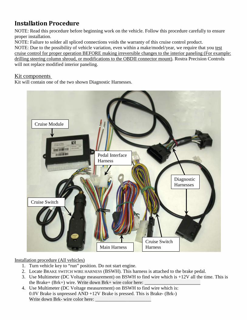
Installation Procedure NOTE: Read this procedure before beginning work on the vehicle. Follow this procedure carefully to ensure proper installation. NOTE: Failure to solder all spliced connections voids the warranty of this cruise control product. NOTE: Due to the possibility of vehicle variation, even within a make/model/year, we require that you test cruise control for proper operation BEFORE making irreversible changes to the interior paneling (For example: drilling steering column shroud, or modifications to the OBDII connector mount). Rostra Precision Controls will not replace modified interior paneling. Kit components Kit will contain one of the two shown Diagnostic Harnesses.
Installation procedure (All vehicles)
1. Turn vehicle key to “run” position. Do not start engine. 2. Locate BRAKE SWITCH WIRE HARNESS (BSWH). This harness is attached to the brake pedal. 3. Use Multimeter (DC Voltage measurement) on BSWH to find wire which is +12V all the time. This is
the Brake+ (Brk+) wire. Write down Brk+ wire color here: _______________________ 4. Use Multimeter (DC Voltage measurement) on BSWH to find wire which is:
0.0V Brake is unpressed AND +12V Brake is pressed. This is Brake- (Brk-) Write down Brk- wire color here: _______________________
Cruise Module
Cruise Switch
Pedal Interface Harness
Cruise Switch Harness Main Harness
Diagnostic Harnesses
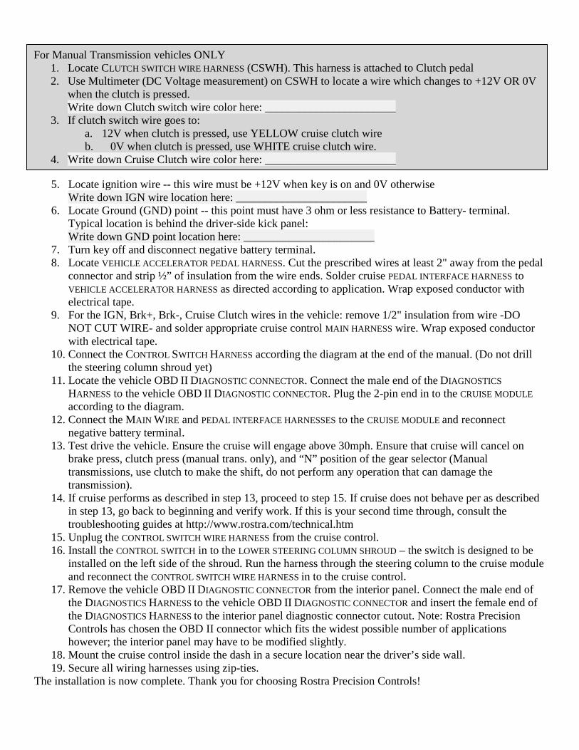
5. Locate ignition wire -- this wire must be +12V when key is on and 0V otherwise Write down IGN wire location here: _______________________
6. Locate Ground (GND) point -- this point must have 3 ohm or less resistance to Battery- terminal. Typical location is behind the driver-side kick panel: Write down GND point location here: _______________________
7. Turn key off and disconnect negative battery terminal. 8. Locate VEHICLE ACCELERATOR PEDAL HARNESS. Cut the prescribed wires at least 2" away from the pedal
connector and strip ½” of insulation from the wire ends. Solder cruise PEDAL INTERFACE HARNESS to VEHICLE ACCELERATOR HARNESS as directed according to application. Wrap exposed conductor with electrical tape.
9. For the IGN, Brk+, Brk-, Cruise Clutch wires in the vehicle: remove 1/2" insulation from wire -DO NOT CUT WIRE- and solder appropriate cruise control MAIN HARNESS wire. Wrap exposed conductor with electrical tape.
10. Connect the CONTROL SWITCH HARNESS according the diagram at the end of the manual. (Do not drill the steering column shroud yet)
11. Locate the vehicle OBD II DIAGNOSTIC CONNECTOR. Connect the male end of the DIAGNOSTICS HARNESS to the vehicle OBD II DIAGNOSTIC CONNECTOR. Plug the 2-pin end in to the CRUISE MODULE according to the diagram.
12. Connect the MAIN WIRE and PEDAL INTERFACE HARNESSES to the CRUISE MODULE and reconnect negative battery terminal.
13. Test drive the vehicle. Ensure the cruise will engage above 30mph. Ensure that cruise will cancel on brake press, clutch press (manual trans. only), and “N” position of the gear selector (Manual transmissions, use clutch to make the shift, do not perform any operation that can damage the transmission).
14. If cruise performs as described in step 13, proceed to step 15. If cruise does not behave per as described in step 13, go back to beginning and verify work. If this is your second time through, consult the troubleshooting guides at http://www.rostra.com/technical.htm
15. Unplug the CONTROL SWITCH WIRE HARNESS from the cruise control. 16. Install the CONTROL SWITCH in to the LOWER STEERING COLUMN SHROUD – the switch is designed to be
installed on the left side of the shroud. Run the harness through the steering column to the cruise module and reconnect the CONTROL SWITCH WIRE HARNESS in to the cruise control.
17. Remove the vehicle OBD II DIAGNOSTIC CONNECTOR from the interior panel. Connect the male end of the DIAGNOSTICS HARNESS to the vehicle OBD II DIAGNOSTIC CONNECTOR and insert the female end of the DIAGNOSTICS HARNESS to the interior panel diagnostic connector cutout. Note: Rostra Precision Controls has chosen the OBD II connector which fits the widest possible number of applications however; the interior panel may have to be modified slightly.
18. Mount the cruise control inside the dash in a secure location near the driver’s side wall. 19. Secure all wiring harnesses using zip-ties.
The installation is now complete. Thank you for choosing Rostra Precision Controls!
For Manual Transmission vehicles ONLY 1. Locate CLUTCH SWITCH WIRE HARNESS (CSWH). This harness is attached to Clutch pedal 2. Use Multimeter (DC Voltage measurement) on CSWH to locate a wire which changes to +12V OR 0V
when the clutch is pressed. Write down Clutch switch wire color here: _______________________
3. If clutch switch wire goes to: a. 12V when clutch is pressed, use YELLOW cruise clutch wire b. 0V when clutch is pressed, use WHITE cruise clutch wire.
4. Write down Cruise Clutch wire color here: _______________________
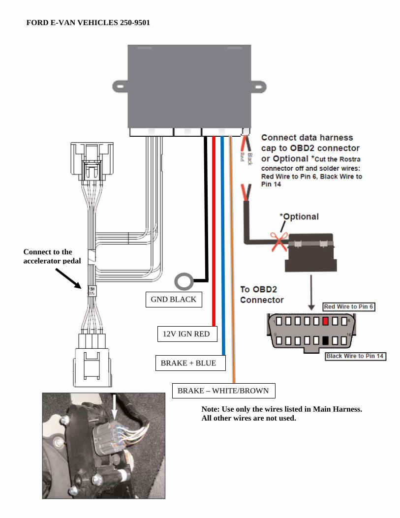
Note: Use only the wires listed in Main Harness. All other wires are not used.
FORD E-VAN VEHICLES 250-9501
12V IGN RED
BRAKE + BLUE
GND BLACK
BRAKE – WHITE/BROWN
Connect to the accelerator pedal
Solder Direction
Pedal Interface Harness Color
Connector Position
CONNECTOR GRAY PIN 5
CONNECTOR WHITE PIN 2
HARNESS BLUE PIN 5
HARNESS GREEN PIN 2 2011 Connector
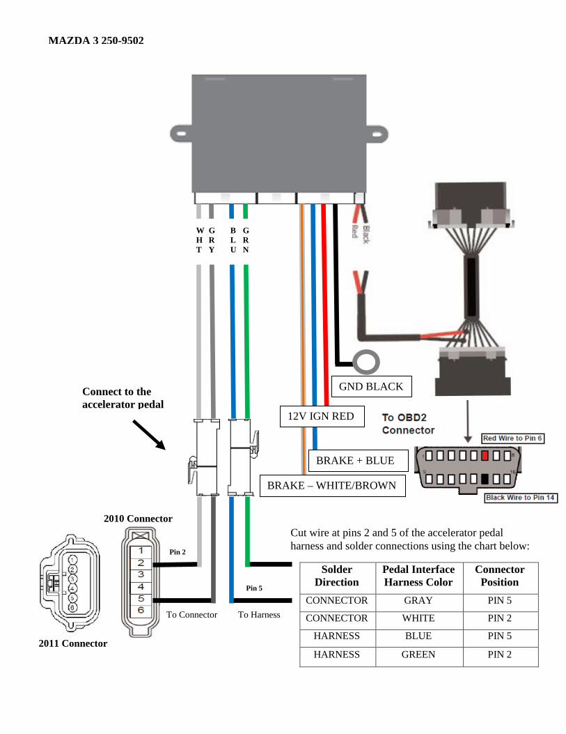
MAZDA 3 250-9502
To Connector To Harness
Cut wire at pins 2 and 5 of the accelerator pedal harness and solder connections using the chart below:
2010 Connector
GND BLACK
BRAKE + BLUE
BRAKE – WHITE/BROWN
12V IGN RED
GRN
BLU
GRY
WHT
Connect to the accelerator pedal
Pin 2
Pin 5
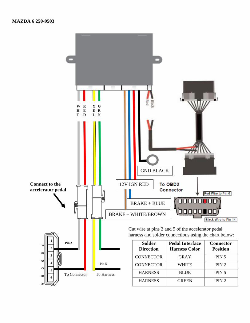
Solder Direction
Pedal Interface Harness Color
Connector Position
CONNECTOR GRAY PIN 5
CONNECTOR WHITE PIN 2
HARNESS BLUE PIN 5
HARNESS GREEN PIN 2
MAZDA 6 250-9503
To Connector To Harness
GND BLACK
BRAKE + BLUE
BRAKE – WHITE/BROWN
12V IGN RED
Cut wire at pins 2 and 5 of the accelerator pedal harness and solder connections using the chart below:
1
2
3
4
5
6
WHT
GRN
RED
YEL
Connect to the accelerator pedal
Pin 2
Pin 5
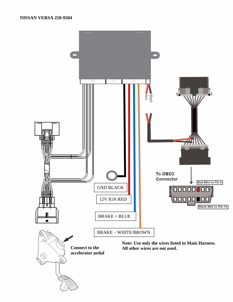
NISSAN VERSA 250-9504
12V IGN RED
BRAKE + BLUE
GND BLACK
BRAKE – WHITE/BROWN
Note: Use only the wires listed in Main Harness. All other wires are not used.
Connect to the accelerator pedal
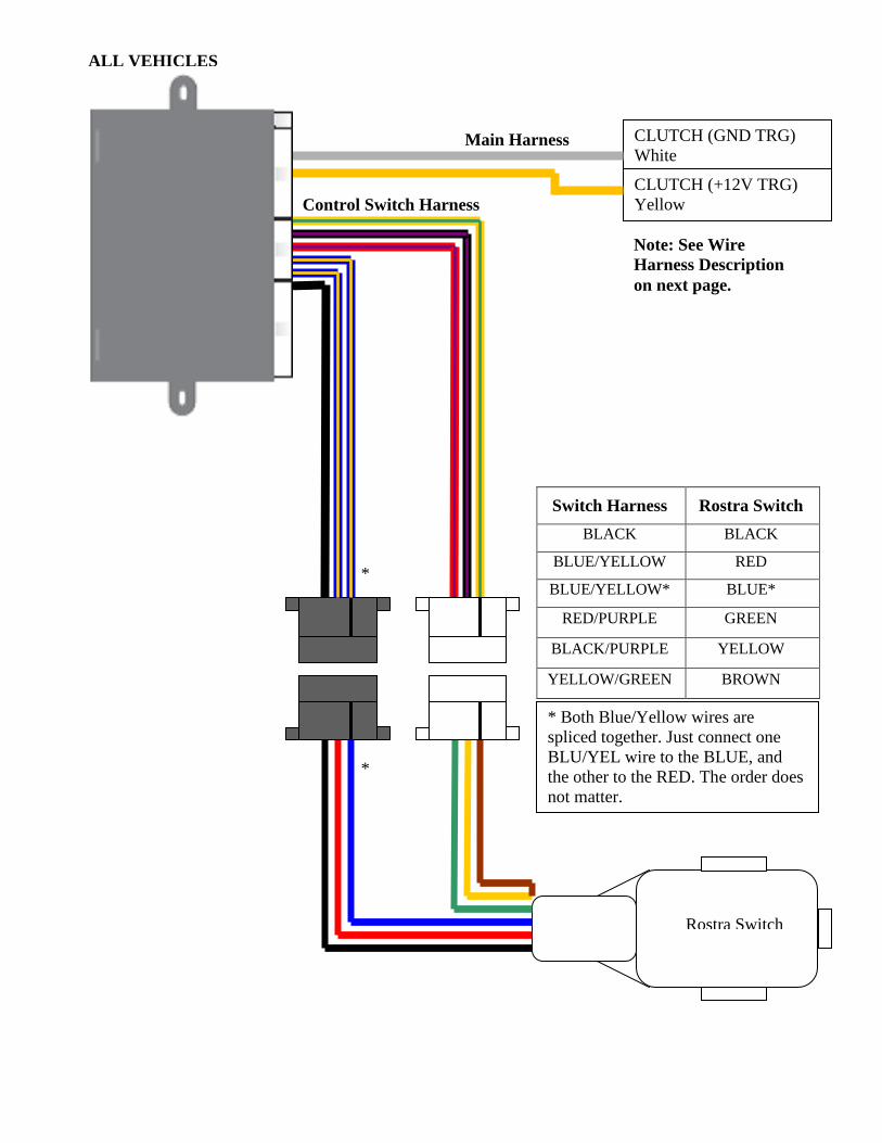
Control Switch Harness
Rostra Switch
Switch Harness Rostra Switch BLACK BLACK
BLUE/YELLOW RED
BLUE/YELLOW* BLUE*
RED/PURPLE GREEN
BLACK/PURPLE YELLOW
YELLOW/GREEN BROWN
*
*
Main Harness
Note: See Wire Harness Description on next page.
CLUTCH (GND TRG) White
CLUTCH (+12V TRG) Yellow
* Both Blue/Yellow wires are spliced together. Just connect one BLU/YEL wire to the BLUE, and the other to the RED. The order does not matter.
Cruise Module
ALL VEHICLES
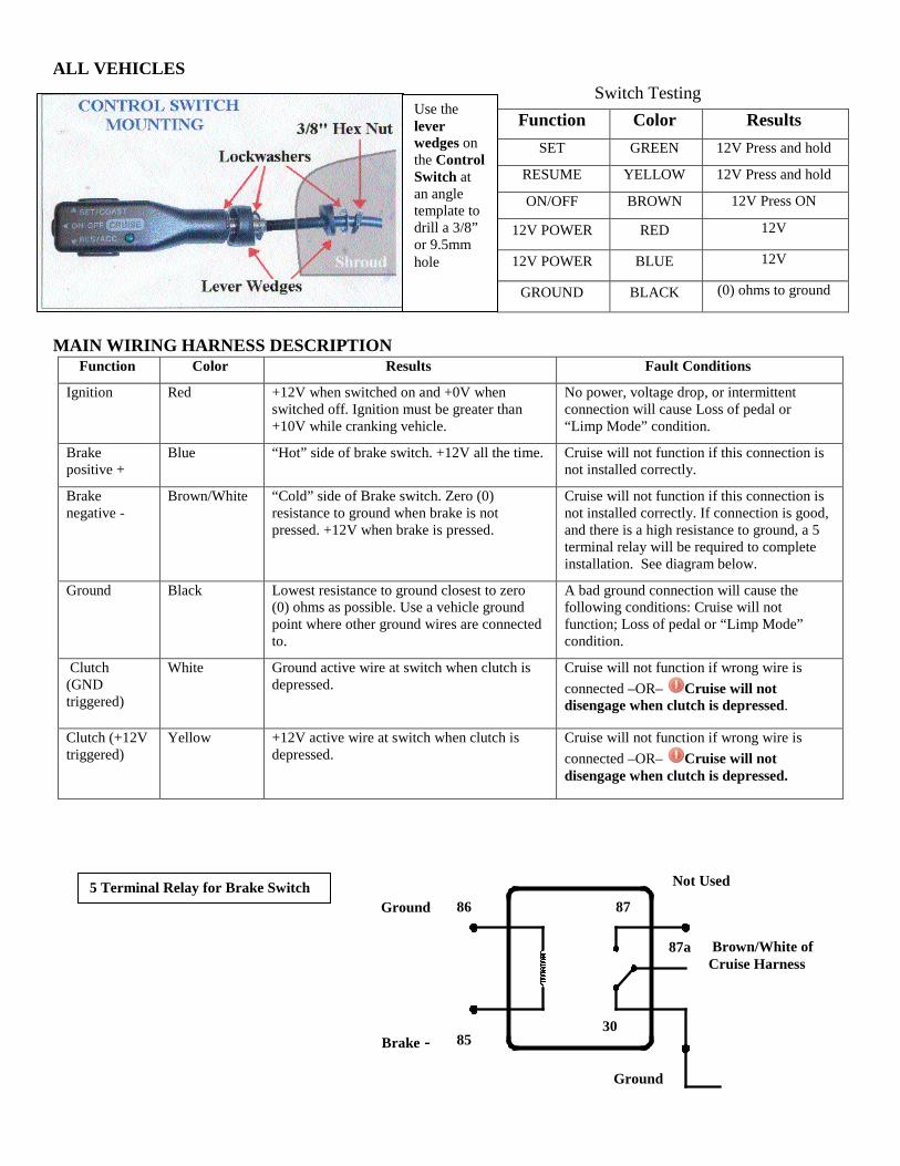
MAIN WIRING HARNESS DESCRIPTION
Function Color Results Fault Conditions
Ignition Red +12V when switched on and +0V when switched off. Ignition must be greater than +10V while cranking vehicle.
No power, voltage drop, or intermittent connection will cause Loss of pedal or “Limp Mode” condition.
Brake positive +
Blue “Hot” side of brake switch. +12V all the time. Cruise will not function if this connection is not installed correctly.
Brake negative -
Brown/White “Cold” side of Brake switch. Zero (0) resistance to ground when brake is not pressed. +12V when brake is pressed.
Cruise will not function if this connection is not installed correctly. If connection is good, and there is a high resistance to ground, a 5 terminal relay will be required to complete installation. See diagram below.
Ground Black Lowest resistance to ground closest to zero (0) ohms as possible. Use a vehicle ground point where other ground wires are connected to.
A bad ground connection will cause the following conditions: Cruise will not function; Loss of pedal or “Limp Mode” condition.
Clutch (GND triggered)
White Ground active wire at switch when clutch is depressed.
Cruise will not function if wrong wire is connected –OR– Cruise will not disengage when clutch is depressed.
Clutch (+12V triggered)
Yellow +12V active wire at switch when clutch is depressed.
Cruise will not function if wrong wire is connected –OR– Cruise will not disengage when clutch is depressed.
5 Terminal Relay for Brake Switch
86
85
87
87a
30
Ground
Brake -
Not Used
Brown/White of Cruise Harness
Ground
Switch Testing Function Color Results
SET GREEN 12V Press and hold
RESUME YELLOW 12V Press and hold
ON/OFF BROWN 12V Press ON
12V POWER RED 12V
12V POWER BLUE 12V
GROUND BLACK (0) ohms to ground
Use the lever wedges on the Control Switch at an angle template to drill a 3/8” or 9.5mm hole
ALL VEHICLES
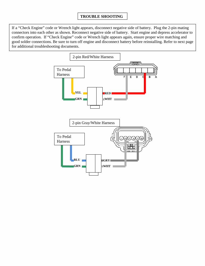
TROUBLE SHOOTING
If a “Check Engine” code or Wrench light appears, disconnect negative side of battery. Plug the 2-pin mating connectors into each other as shown. Reconnect negative side of battery. Start engine and depress accelerator to confirm operation. If “Check Engine” code or Wrench light appears again, ensure proper wire matching and good solder connections. Be sure to turn off engine and disconnect battery before reinstalling. Refer to next page for additional troubleshooting documents.
2-pin Red/White Harness
RED
WHT GRN
YEL
To Pedal Harness
2-pin Gray/White Harness
GRY
WHT GRN
BLU
To Pedal Harness
TECHNICAL TIPS
Loss of Pedal/Limp Mode/Check Engine/Wrench Light:
1. Check Red power wire at control module for +12 volts with ignition on and 0 volts when switched off. Ignition must be greater than 10 volts while cranking and with engine running.
2. Check Black ground wire for lowest resistance to ground and less than 5 ohms. Use a vehicle ground point where other ground wires are connected to.
3. Check Pedal Interface Harness connections for cold solder joints. Do not use splice connectors. Check 2-pin connectors of Pedal Interface Harness for complete connection. Check continuity from each spliced vehicle wire at accelerator pedal to Pedal Interface Harness connector at control module.
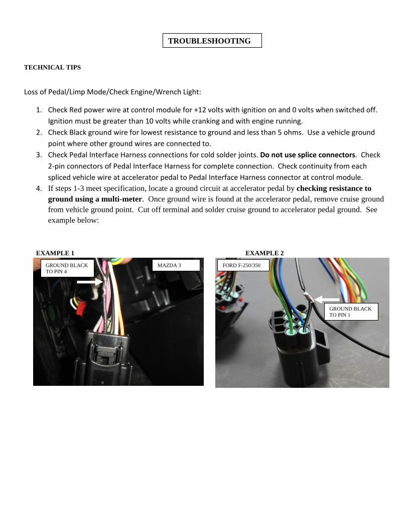
4. If steps 1-3 meet specification, locate a ground circuit at accelerator pedal by checking resistance to ground using a multi-meter. Once ground wire is found at the accelerator pedal, remove cruise ground from vehicle ground point. Cut off terminal and solder cruise ground to accelerator pedal ground. See example below:
EXAMPLE 1 EXAMPLE 2
GROUND BLACK TO PIN 4
TROUBLESHOOTING
GROUND BLACK TO PIN 1
FORD F-250/350 MAZDA 3