CRUISE CONTROL WITH ELECTRIC ACTUATOR Group...
14
CRUISE CONTROL WITH ELECTRIC ACTUATOR Group 61 - Chassis Electrics Produced By: BMW of North America, Inc Issued 7/83 61-09
-
Upload
truongdang -
Category
Documents
-
view
223 -
download
2
Transcript of CRUISE CONTROL WITH ELECTRIC ACTUATOR Group...
CRUISE CONTROL WITH ELECTRIC ACTUATOR
Group 61 - Chassis Electrics
Produced By:
BMW of North America, Inc
Issued 7/83 61-09
CRUISE CONTROL WITH ELECTRIC ACTUATOR
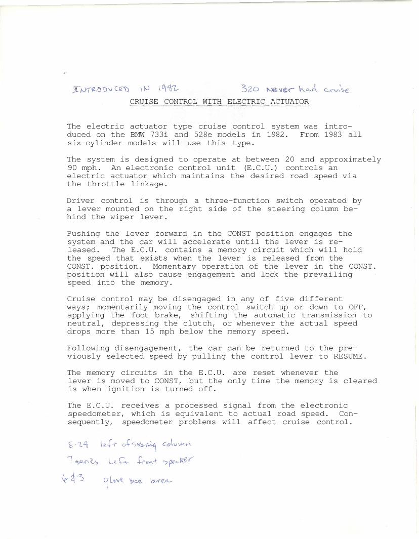
The electric actuator type cruise control system was intro-duced on the BMW 733i and 528e models in 1982. From 1983 allsix-cylinder models will use this type.
The system is designed to operate at between 20 and approximately90 mph. An electronic control unit (E.C.U.) controls anelectric actuator which maintains the desired road speed viathe throttle linkage.
Driver control is through a three-function switch operated bya lever mounted on the right side of the steering column be-hind the wiper lever.
Pushing the lever forward in the CONST position engages thesystem and the car will accelerate until the lever is re-leased. The E.C.U. contains a memory circuit which will holdthe speed that exists when the lever is released from theCONST. position. Momentary operation of the lever in the CONST.position will also cause engagement and lock the prevailingspeed into the memory.
Cruise control may be disengaged in any of five differentways; momentarily moving the control switch up or down to OFF,applying the foot brake, shifting the automatic transmission toneutral, depressing the clutch, or whenever the actual speeddrops more than 15 mph below the memory speed.
Following disengagement, the car can be returned to the pre-viously selected speed by pulling the control lever to RESUME.
The memory circuits in the E.C.U. are reset whenever thelever is moved to CONST, but the only time the memory is clearedis when ignition is turned off.
The E.C.U. receives a processed signal from the electronicspeedometer, which is equivalent to actual road speed. Con-sequently, speedometer problems will affect cruise control.
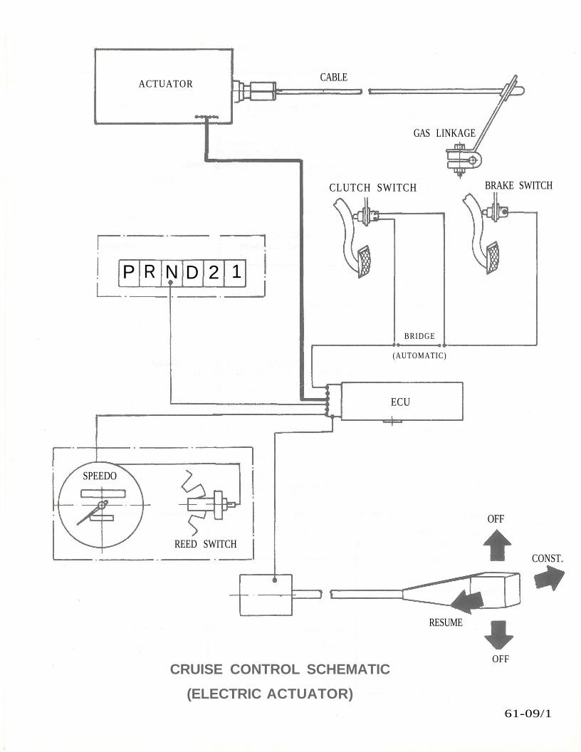
ACTUATOR
CLUTCH SWITCH BRAKE SWITCH
CRUISE CONTROL SCHEMATIC
(ELECTRIC ACTUATOR)
OFF
61-09/1
CABLE
GAS LINKAGE
BRIDGE
(AUTOMATIC)
ECU
SPEEDO
OFF
REED SWITCH
RESUME
CONST.
R N D 2 1P
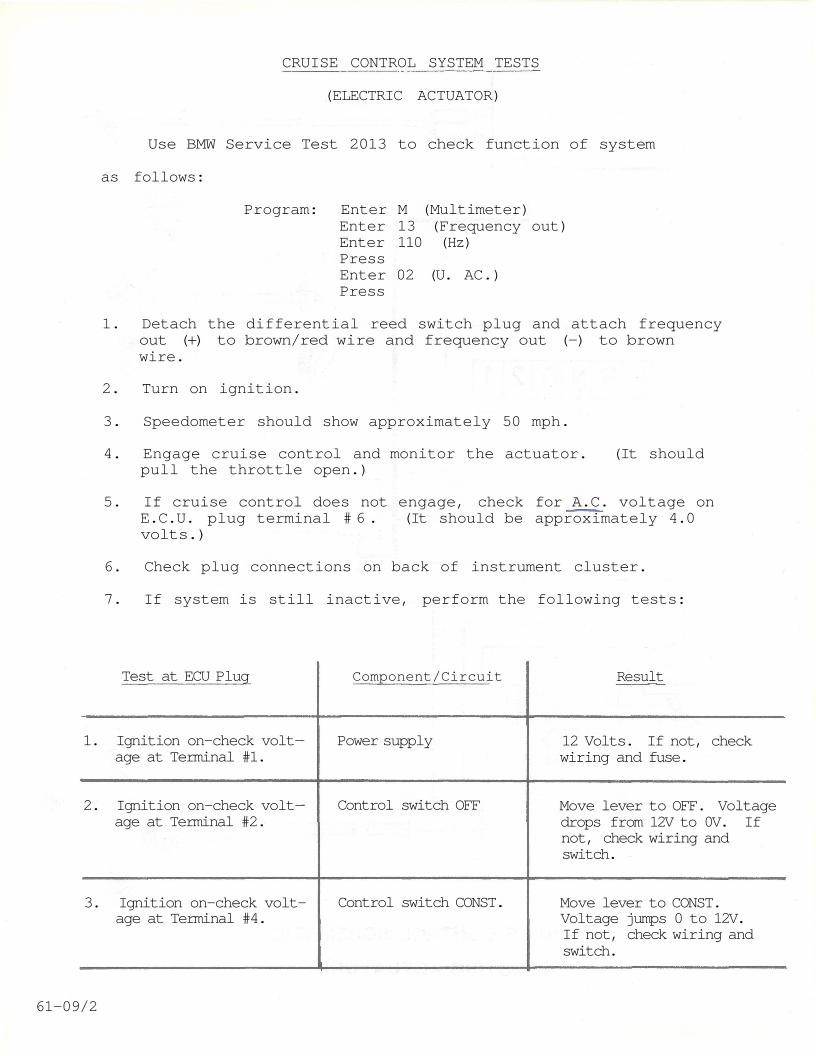
CRUISE CONTROL SYSTEM TESTS
(ELECTRIC ACTUATOR)
Use BMW Service Test 2013 to check function of system
as follows:
Program: Enter M (Multimeter)Enter 13 (Frequency out)Enter 110 (Hz)PressEnter 02 (U. AC.)Press
1. Detach the differential reed switch plug and attach frequencyout (+) to brown/red wire and frequency out (-) to brownwire.
2. Turn on ignition.
3. Speedometer should show approximately 50 mph.
4. Engage cruise control and monitor the actuator. (It shouldpull the throttle open.)
5. If cruise control does not engage, check for A.C. voltage onE.C.U. plug terminal # 6 . (It should be approximately 4.0volts.)
6. Check plug connections on back of instrument cluster.
7. If system is still inactive, perform the following tests:
Test at ECU Plug Component/Circuit Result
1. Ignition on—check volt-age at Terminal #1.
Power supply 12 Volts. If not, checkwiring and fuse.
2. Ignition on—check volt-age at Terminal #2.
Control switch OFF Move lever to OFF. Voltagedrops from 12V to 0V. Ifnot, check wiring andswitch.
3. Ignition on—check volt-age at Terminal #4.
Control switch CONST. Move lever to CONST.Voltage jumps 0 to 12V.If not, check wiring andswitch.
61-09/2
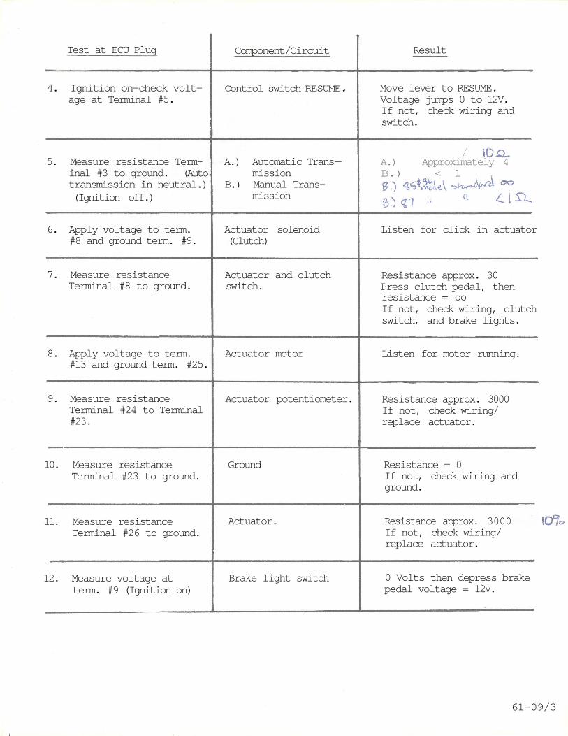
Test at ECU Plug Component/Circuit Result
4. Ignition on—check volt-age at Terminal #5.
Control switch RESUME. Move lever to RESUME.Voltage jumps 0 to 12V.If not, check wiring andswitch.
5. Measure resistance Term-inal #3 to ground. (Autotransmission in neutral.)(Ignition off.)
A.) Automatic Trans-mission
B.) Manual Trans-mission
A.) Approximately 4B.) < 1
6. Apply voltage to term.#8 and ground term. #9.
Actuator solenoid(Clutch)
Listen for click in actuator
7. Measure resistanceTerminal #8 to ground.
Actuator and clutchswitch.
Resistance approx. 30Press clutch pedal, thenresistance = ooIf not, check wiring, clutchswitch, and brake lights.
8. Apply voltage to term.#13 and ground term. #25.
Actuator motor Listen for motor running.
9. Measure resistanceTerminal #24 to Terminal#23.
Actuator potentiometer. Resistance approx. 3000If not, check wiring/replace actuator.
10. Measure resistanceTerminal #23 to ground.
Ground Resistance = 0If not, check wiring andground.
11. Measure resistanceTerminal #26 to ground.
Actuator. Resistance approx. 3000If not, check wiring/replace actuator.
12. Measure voltage atterm. #9 (Ignition on)
Brake light switch 0 Volts then depress brakepedal voltage = 12V.
61-09/3
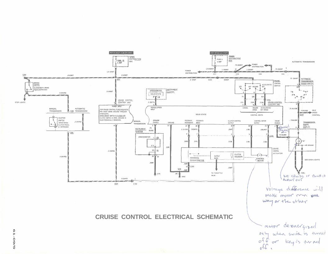
FOR CRUISE CONTROL TO BE E N G A G E DPIN 9 MUST SENSE GROUND THROUGHSTOPLIGHTS.WHEN BRAKE SWITCH IS CLOSED ORCLUTCH SWITCH IS OPEN, GROUND ISELECTRONICALLY REMOVED.
CRUISE CONTROL ELECTRICAL SCHEMATIC
BRAKE
SWITCH
C L O S E D WITH BRAKEPEDAL DEPRESSED
POWER
DISTRIBUTION
BOX
CLUTCH
SWITCH
OPENS WHENCLUTCH P E D A LIS DEPRESSED
POWERDISTRIBUTION
BOX
AUTOMATIC
TRANSMISSION
RANGE SWITCH
AUTOMATIC TRANSMISSION
CRUISE
CONTROL
SWITCH
C210
CRUISE CONTROL
CONTROL UNIT
TRANSMISSION
RANGE
DISPLAY
T O T H R O T T L E
VALVE
FEEDBACK
POTENTIOMETER
INSTRUMENT
CLUSTER
CRUISE
CONTROL
A C T U A T O RCLUTCH
SOLENOID
CANCEL RESUME ACCELERATE/SPEED SET SPEED
CONTROL INPUTS
INSTRUMENT
CLUSTER
MANUAL
TRANSMISSION
IDLE
SPEED
CONTROL
FUSE 6
8 AMP
POWER
DISTRIBUTION
POWER
DISTRIBUTION
ACCELERATE/SETOFF RESUMEOFF
S217 C206 S309 C301
.75 GN/WT
.5 VI/WT C210 GN/WT
CLUTCH CONTROL CONTROL MOTOR CRUISEOUTPUT OUTPUT ENABLE
SEE DASH LIGHTS
GROUND
"N"
OUTPUTBAND
1.5 GN/WT 1 GN/WT 11 1 GN/WT .75 GN/WT
.75 GN/WT
1
.75 8U/3R
.75 BU/BR
S234
3
15
1
2
D
6
N
R
PSW0
GN BU
. 5 YL .5 GN .5 BU45
SPEEDOMETER
SOLID STATE
2 C8
.5 BU/YLCRUISE CONTROL
CONTROL UNIT
POWER INPUT
.5 VI/WTC250
STOP LIGHTS
.5 GN/RD
. 5 G N / R D
MANUAL
TRANSMISSION
AUTOMATIC
TRANSMISSIONC208
.5 GN/RD
C208
61
-0
9/5
S224
.5 GN/RD
.5 GN/RD
9
G200
.5 BR
SPEEDOMETER
.5 VI/WT
1.5 VI/WT
S241
FUSE 128 AMP
.5 VI/WT
VEHICLE SPEEDINPUT
CRUISEENABLE
.75
BU/BR
C8
GROUNDFEEDBACKREFERENCE
FEEDBACKINPUT
SOLID STATE
24 26
.5 GY/RD .5 GN/YL
4
.5 RD
7
.5 YL
.5 BR
3S233
(-)
12
16 C1
C6
.5 BR
.5 BR
G200
.5 BR
.75 BU/BR
6
7
.75 BU/BR
.5 BU
C209
.5 BU/WT
2
3
G200
13
.5 BK
5
.5 BK.5 GN
.5 WT
.5 WT
CONTROLMOTOR
1
CRUISE CONTROL WITH VACUUM SERVO
Group 61 - Chassis Electrics
Produced by
BMW OF NORTH AMERICA, INC.
Revised 7/83 61-08
CRUISE CONTROL
The BMW cruise control is designed to operate between 20and approximately 90 mph. An electronic control unit (E.C.U.)controls a vacuum operated servo unit which actuates thethrottle linkage to maintain the required road speed.
Drive control is through a three function switch operatedby a lever mounted on the right side of the steering columnbehind the wiper lever.
Pushing the lever forward in the CONST position engages thesystem and the car will accelerate until the lever isreleased. The E.C.U. contains a memory circuit which willhold the speed that exists when the lever is released fromthe CONST position. Momentary operation of the lever in theCONST position will also cause engagement and lock theprevailing speed into the memory.
Cruise control may be disengaged in any of five differentways: momentarily moving the control switch up or down toOFF, applying the foot brake, shifting the transmission toneutral, or whenever the actual speed drops more than 7 mphbelow the memory speed.
Following disengagement, the car can be returned to thepreviously selected speed by pulling the control lever toRESUME.
The memory circuits in the E.C.U. are reset whenever thelever is moved to CONST but the only time the memory iscleared is when ignition is turned off.
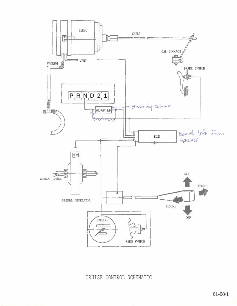
SPEEDO CABLE
SIGNAL GENERATOR
OFF
CONST.
CRUISE CONTROL SCHEMATIC
61-08/1
SERVOCABLE
VACUUMVENT
GAS LINKAGE
BRAKE SWITCH
P R N D 2 1
ADAPTER
ECU
RESUME
OFF
REED SWITCH
SPEEDO
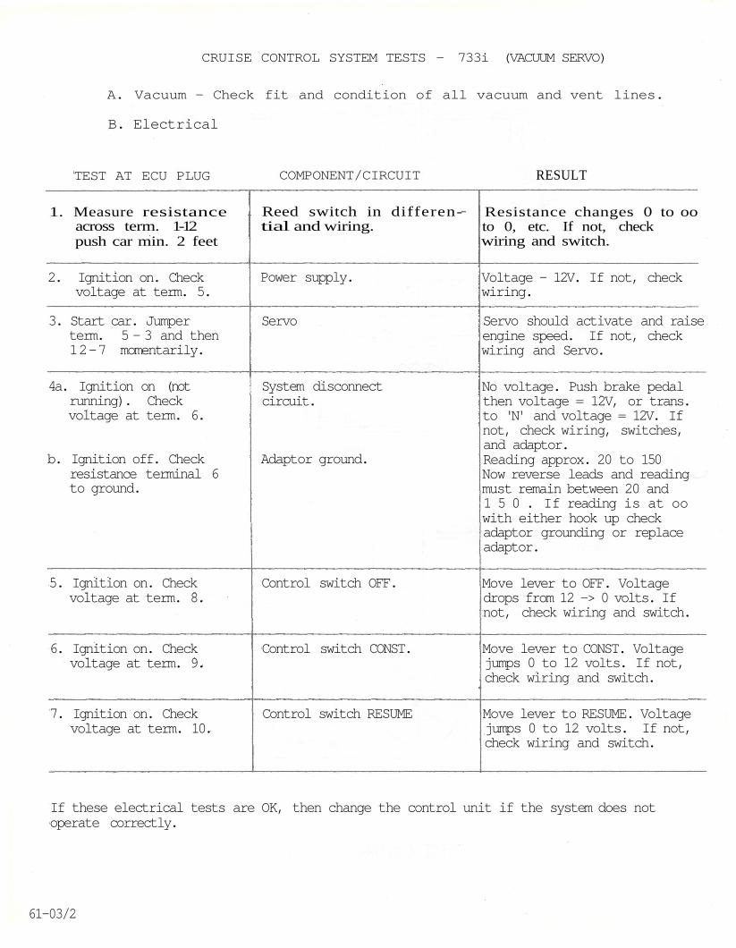
CRUISE CONTROL SYSTEM TESTS - 733i (VACUUM SERVO)
A. Vacuum - Check fit and condition of all vacuum and vent lines.
B. Electrical
TEST AT ECU PLUG COMPONENT/CIRCUIT RESULT
1. Measure resistanceacross term. 1-12push car min. 2 feet
Reed switch in differen-tial and wiring.
Resistance changes 0 to ooto 0, etc. If not, checkwiring and switch.
2. Ignition on. Checkvoltage at term. 5.
Power supply. Voltage - 12V. If not, checkwiring.
3. Start car. Jumperterm. 5 - 3 and then12-7 momentarily.
Servo Servo should activate and raiseengine speed. If not, checkwiring and Servo.
4a. Ignition on (notrunning). Checkvoltage at term. 6.
b. Ignition off. Checkresistance terminal 6to ground.
System disconnectcircuit.
Adaptor ground.
No voltage. Push brake pedalthen voltage = 12V, or trans.to 'N' and voltage = 12V. Ifnot, check wiring, switches,and adaptor.Reading approx. 20 to 150Now reverse leads and readingmust remain between 20 and1 5 0 . If reading is at oowith either hook up checkadaptor grounding or replaceadaptor.
5. Ignition on. Checkvoltage at term. 8.
Control switch OFF. Move lever to OFF. Voltagedrops from 12 -> 0 volts. Ifnot, check wiring and switch.
6. Ignition on. Checkvoltage at term. 9.
Control switch CONST. Move lever to CONST. Voltagejumps 0 to 12 volts. If not,check wiring and switch.
7. Ignition on. Checkvoltage at term. 10.
Control switch RESUME Move lever to RESUME. Voltagejumps 0 to 12 volts. If not,check wiring and switch.
If these electrical tests are OK, then change the control unit if the system does notoperate correctly.
61-03/2
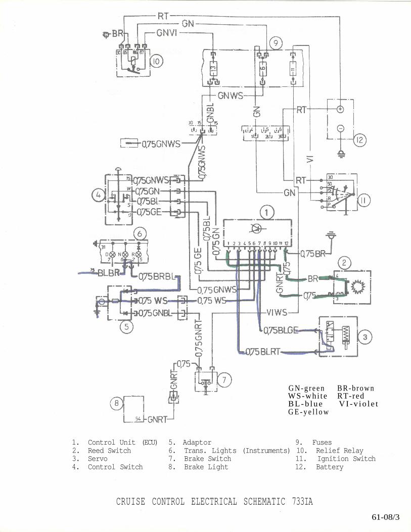
CRUISE CONTROL ELECTRICAL SCHEMATIC 733IA61-08/3
G N - g r e e n BR-b rownWS-whi t e RT-redB L - b l u e VI -v io l e tG E - y e l l o w
1. Control Unit (ECU) 5. Adaptor 9. Fuses2. Reed Switch 6. Trans. Lights (Instruments) 10. Relief Relay3. Servo 7. Brake Switch 11. Ignition Switch4. Control Switch 8. Brake Light 12. Battery
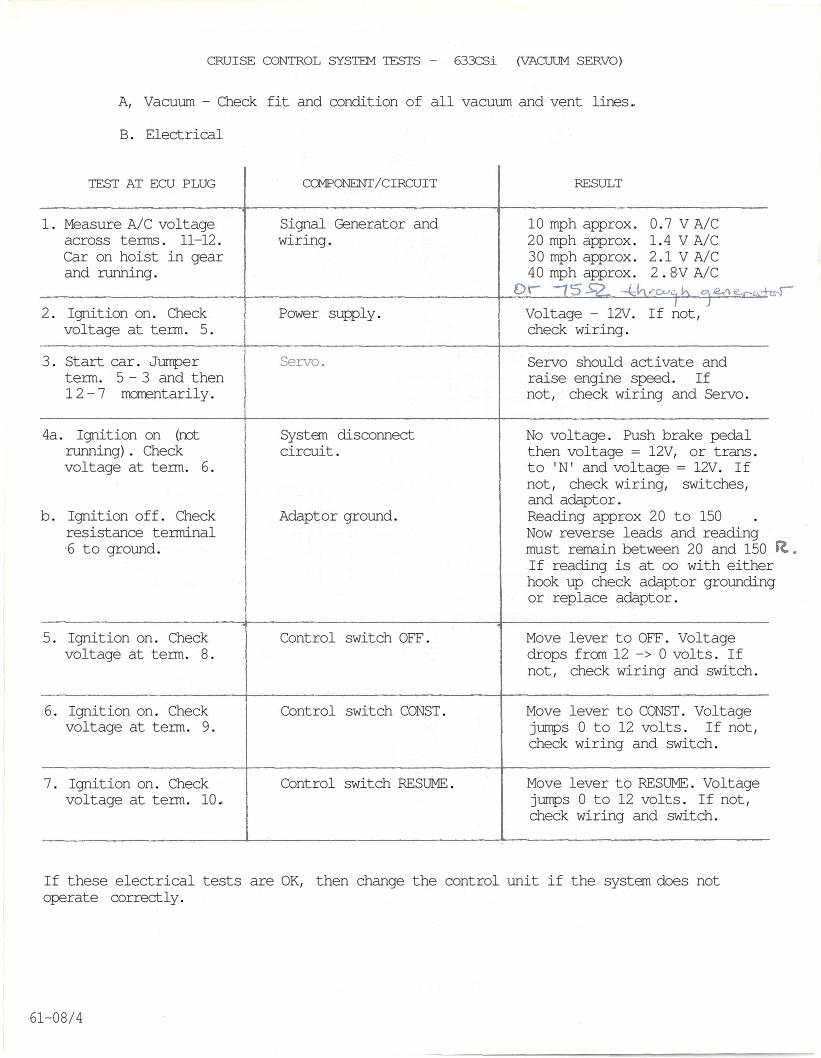
CRUISE CONTROL SYSTEM TESTS - 633CSi (VACUUM SERVO)
A, Vacuum - Check fit and condition of all vacuum and vent lines.
B. Electrical
TEST AT ECU PLUG COMPONENT/CIRCUIT RESULT
1. Measure A/C voltageacross terms. 11-12.Car on hoist in gearand running.
Signal Generator andwiring.
10 mph approx. 0.7 V A/C20 mph approx. 1.4 V A/C30 mph approx. 2.1 V A/C40 mph approx. 2.8V A/C
2. Ignition on. Checkvoltage at term. 5.
Power supply. Voltage - 12V. If not,check wiring.
3. Start car. Jumperterm. 5 - 3 and then12-7 momentarily.
Servo. Servo should activate andraise engine speed. Ifnot, check wiring and Servo.
4a. Ignition on (notrunning). Checkvoltage at term. 6.
b. Ignition off. Checkresistance terminal6 to ground.
System disconnectcircuit.
Adaptor ground.
No voltage. Push brake pedalthen voltage = 12V, or trans.to 'N' and voltage = 12V. Ifnot, check wiring, switches,and adaptor.Reading approx 20 to 150 .Now reverse leads and readingmust remain between 20 and 150If reading is at oo with eitherhook up check adaptor groundingor replace adaptor.
5. Ignition on. Checkvoltage at term. 8.
Control switch OFF. Move lever to OFF. Voltagedrops from 12 -> 0 volts. Ifnot, check wiring and switch.
6. Ignition on. Checkvoltage at term. 9.
Control switch CONST. Move lever to CONST. Voltagejumps 0 to 12 volts. If not,check wiring and switch.
7. Ignition on. Checkvoltage at term. 10.
Control switch RESUME. Move lever to RESUME. Voltagejumps 0 to 12 volts. If not,check wiring and switch.
If these electrical tests are OK, then change the control unit if the system does notoperate correctly.
61-08/4
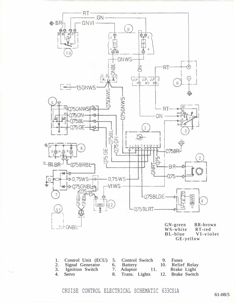
CRUISE CONTROL ELECTRICAL SCHEMATIC 633CSiA61-08/5
1. Control Unit (ECU) 5. Control Switch 9. Fuses2. Signal Generator 6. Battery 10. Relief Relay3. Ignition Switch 7. Adaptor 11. Brake Light4. Servo 8. Trans. Lights 12. Brake Switch
GN-green BR-brownW S - w h i t e RT- redBL-b lue V I - v i o l e t
G E - y e l l o w
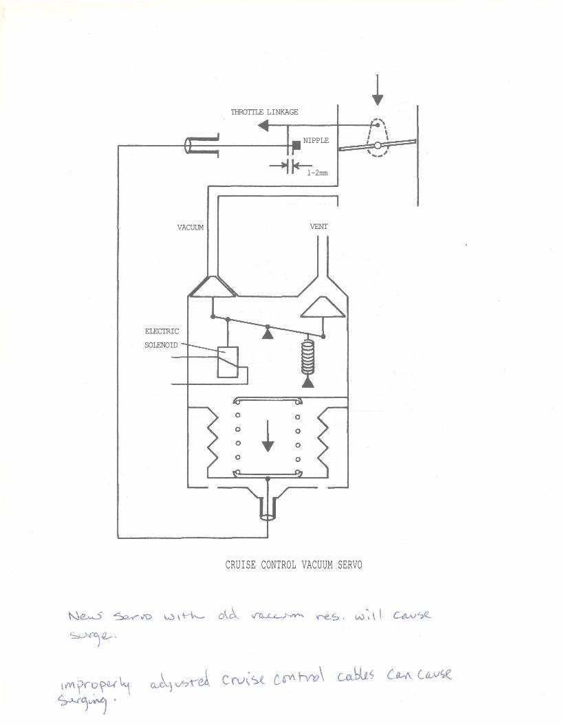
CRUISE CONTROL VACUUM SERVO
THROTTLE LINKAGE
NIPPLE
l-2mm
VENTVACUUM
ELECTRIC
SOLENOID