Crown Site ID# 806387; T-Mobile Site ID# CTHA808A #14 ...
100
April 9, 2021 Melanie A. Bachman Executive Director Connecticut Siting Council 10 Franklin Square New Britain, CT 06051 RE: Notice of Exempt Modification for T-Mobile Crown Site ID# 806387; T-Mobile Site ID# CTHA808A #14 Route 80, Killingworth, CT 06419 Latitude: 41° 21′ 26.43″/ Longitude: -72° 31′ 11.83″ Dear Ms. Bachman: T-Mobile currently maintains six (6) antennas at the 140-foot mount on the existing 160-foot Self Support Tower located at 14 Route 80 in Killingworth. The property is owned by 14 Route 80 LLC and the Tower is owned by Crown Castle. T-Mobile now intends to replace six (6) existing antennas and add three (3) new antennas. This modification/proposal includes hardware that is both 4G(LTE) and 5G capable through remote software configuration and either or both services may be turned on or off at various times. Planned Modifications: Tower: Remove and Replace: (3) RFS – APXVTMI4-ALU-I20 Antennas (REMOVE) - (3) RFS – APX16DWV-16DWV-S-E-A20 Antennas (REPLACE) (3) Commscope – NNVV-65B-R4 Antennas (REMOVE) – (3) RFS – APXVAALL24_43-U-NA20 Antennas (REPLACE) Install New: (3) AIR6449 B41 Antennas (3) Ericsson – Radio 4415 B66A (3) Ericsson – Radio 4449 B71+B85A (3) Ericsson – Radio 4424 B25 (4) 6x24 HCS 4AWG 100m 1 5/8’’ feedlines Remove: (3) Alcatel Lucent 1900MHz 4x45W-65 MHz radio (3) Alcatel Lucent - TD-RRH8x20-25 radio (6) Alcatel Lucent – RRH2x50-800 radio
Transcript of Crown Site ID# 806387; T-Mobile Site ID# CTHA808A #14 ...

April 9, 2021
Melanie A. Bachman Executive Director Connecticut Siting Council 10 Franklin Square New Britain, CT 06051
RE: Notice of Exempt Modification for T-Mobile Crown Site ID# 806387; T-Mobile Site ID# CTHA808A #14 Route 80, Killingworth, CT 06419 Latitude: 41° 21′ 26.43″/ Longitude: -72° 31′ 11.83″
Dear Ms. Bachman:
T-Mobile currently maintains six (6) antennas at the 140-foot mount on the existing 160-foot Self Support Tower located at 14 Route 80 in Killingworth. The property is owned by 14 Route 80 LLC and the Tower is owned by Crown Castle. T-Mobile now intends to replace six (6) existing antennas and add three (3) new antennas. This modification/proposal includes hardware that is both 4G(LTE) and 5G capable through remote software configuration and either or both services may be turned on or off at various times.
Planned Modifications: Tower:
Remove and Replace: (3) RFS – APXVTMI4-ALU-I20 Antennas (REMOVE) - (3) RFS – APX16DWV-16DWV-S-E-A20Antennas (REPLACE)
(3) Commscope – NNVV-65B-R4 Antennas (REMOVE) – (3) RFS – APXVAALL24_43-U-NA20Antennas (REPLACE)
Install New: (3) AIR6449 B41 Antennas(3) Ericsson – Radio 4415 B66A(3) Ericsson – Radio 4449 B71+B85A(3) Ericsson – Radio 4424 B25(4) 6x24 HCS 4AWG 100m 1 5/8’’ feedlines
Remove: (3) Alcatel Lucent 1900MHz 4x45W-65 MHz radio(3) Alcatel Lucent - TD-RRH8x20-25 radio(6) Alcatel Lucent – RRH2x50-800 radio
rzajac
Text Box

Melanie A. Bachman
Page 2
Ground:
Install New: (1) SSC 6160 cabinet(1) B160 battery cabinet(1) BB6648(3) BB6630(1) DUG20(1) PSU 4813 voltage booster(1) IXRe router
This facility was originally approved by the Siting Council in Docket #69. The approval was given with conditions which this proposal complies with.
Please accept this letter as notification pursuant to Regulations of Connecticut State Agencies §16-50j-73, for construction that constitutes an exempt modification pursuant to R.C.S.A. § 16-50j-72(b)(2). In accordance with R.C.S.A. § 16-50j-73, a copy of this letter is being sent to Catherine Lino, First Selectwoman for the Town ofKillingworth, as well as Cathie Jefferson, Zoning Enforcement Officer for the Town of Killingworth. A copy of thisapplication will also be sent to the property owner.
1. The proposed modifications will not require the extension of the site boundary.
2. The proposed modification will not increase noise levels at the facility by six decibels or more, orto levels that exceed state and local criteria.
3. The operation of the replacement antennas will not increase radio frequency emissions at the facility toa level at or above the Federal Communication Commission safety standard.
4. The proposed modifications will not cause a change or alteration in the physical or environmentalcharacteristics of the site.
5. The existing structure and its foundation can support the proposed loading.
For the foregoing reasons, T-Mobile respectfully submits that the proposed modifications to the above-reference telecommunications facility constitutes an exempt modification under R.C.S.A. § 16-50j-72(b)(2).
Melanie A. Bachman
Page 3
Sincerely,
Richard Zajac Site Acquisition Specialist 4545 East River Road, Suite 320 West Henrietta, NY (585) [email protected]
cc:
The Honorable Catherine Iino, First Selectwoman (via email only to [email protected]) Town of Killingworth 323 Route 81 Killingworth, CT 06419
Cathie S. Jefferson, Zoning Enforcement Officer (via email only to [email protected]) Town of Killingworth 323 Route 81 Killingworth, CT 06419
14 Route 80 LLC 93A Glenwood Road Clinton, CT 06413

1
Zajac, Richard
From: Zajac, RichardSent: Friday, April 9, 2021 1:03 PMTo: [email protected]: Connecticut Siting Council exempt modification application notificationAttachments: CSC Exempt Modification Application - 14 Route 80.pdf
Good afternoon, Please see the attached application to the Connecticut Siting Council regarding antenna work on the existing cell tower located at 14 Route 80 in Killingworth. Should you have any questions/comments/concerns regarding this application, please do not hesitate to contact me. Thank you, RICH ZAJAC Site Acquisition Specialist T: (585) 445-5896 M: (607) 346-7212 F: (724) 416-4461 CROWN CASTLE 4545 East River Road, Suite 320 West Henrietta, NY 14586

1
Zajac, Richard
From: Zajac, RichardSent: Friday, April 9, 2021 1:04 PMTo: [email protected]: Connecticut Siting Council exempt modification application notificationAttachments: CSC Exempt Modification Application - 14 Route 80.pdf
Good afternoon, Please see the attached application to the Connecticut Siting Council regarding antenna work on the existing cell tower located at 14 Route 80 in Killingworth. Should you have any questions/comments/concerns regarding this application, please do not hesitate to contact me. Thank you, RICH ZAJAC Site Acquisition Specialist T: (585) 445-5896 M: (607) 346-7212 F: (724) 416-4461 CROWN CASTLE 4545 East River Road, Suite 320 West Henrietta, NY 14586


Exhibit A
Original Facility Approval


rzajac
Stamp

Exhibit C
Construction Drawings

IT IS A VIOLATION OF LAW FOR ANY PERSON,UNLESS THEY ARE ACTING UNDER THE DIRECTION
OF A LICENSED PROFESSIONAL ENGINEER,TO ALTER THIS DOCUMENT.
0T-1REVISION:SHEET NUMBER:
ISSUED FOR:
DRWNREV DESCRIPTION DES./QADATE
1200 MACARTHUR BLVD, SUITE 200MAHWAH, NJ 07430
T-MOBILE SITE NUMBER:CTHA808A
BU #: 806387HRT 088 943629
#14 ROUTE 80KILLINGWORTH, CT 06419
EXISTING 160'-0"SELF-SUPPORT
TOWERENGINEERINGPROFESSIONALS
326 TRYON RDRALEIGH, NC 27603(919) 661-6351
35 GRIFFIN ROADBLOOMFIELD, CT 06002
TEP JOB #: 45443.498699
A 03/02/21 JW BSEPRELIMINARY
03/17/21
SEAL:
0 03/17/21 JW BSECONSTRUCTION
T-MOBILE SPRINT-RETAIN SITE CONFIGURATION: 67D5997DB_2xAIR+1OP
T-MOBILE SITE NUMBER:T-MOBILE SITE NAME:SITE TYPE:TOWER HEIGHT:
BUSINESS UNIT #:SITE ADDRESS:COUNTY:JURISDICTION:
CTHA808ACTHA808ASELF-SUPPORT160'-0"
806387
MIDDLESEXTOWN OF KILLINGWORTH
#14 ROUTE 80KILLINGWORTH, CT 06419
APPROVALS
THE PARTIES ABOVE HEREBY APPROVE AND ACCEPT THESE DOCUMENTSAND AUTHORIZE THE CONTRACTOR TO PROCEED WITH THECONSTRUCTION DESCRIBED HEREIN. ALL CONSTRUCTION DOCUMENTSARE SUBJECT TO REVIEW BY THE LOCAL BUILDING DEPARTMENT ANDANY CHANGES AND MODIFICATIONS THEY MAY IMPOSE.
APPROVAL SIGNATURE DATE
RF
CONST.
FAA
OPS
RE
SR DEV MGR
REG DIR
LOCATION MAP
NO SCALE
SITE INFORMATION
CARRIER/APPLICANT:
NORTHEAST UTILITIES(800) 286-2000
ELECTRIC PROVIDER:
AT&T(800) 288-2020
TELCO PROVIDER:
GROUND ELEVATION:
41° 21' 26.43" (41.35735278)
-72° 31' 11.83" (-72.51991667)
FACILITY IS UNMANNED AND NOT FORHUMAN HABITATION
A.D.A. COMPLIANCE:
MAP/PARCEL #:
TOWN OF KILLINGWORTHJURISDICTION:
34-36A
HRT 088 943629
MIDDLESEX
AREA OF CONSTRUCTION: EXISTING
NAD83
RESIDENTIAL
PROPERTY OWNER:
CROWN CASTLE USA, INC.1200 MACARTHUR BLVD, SUITE 200MAHWAH, NJ 07430
TOWER OWNER:
IIBTYPE OF CONSTRUCTION:
455 FT
#14 ROUTE 80KILLINGWORTH, CT 06419
14 ROUTE 80 LLC93A GLENWOOD RDCLINTON, CT 06413
CROWN CASTLE USA INC.SITE NAME:
LAT/LONG TYPE:
LONGITUDE:
LATITUDE:
CURRENT ZONING:
COUNTY:
SITE ADDRESS:
CALL CONNECTICUT ONE CALL
(800) 922-4455 CBYD.COMCALL 2 WORKING DAYS
BEFORE YOU DIG!
PROJECT TEAM
A&E FIRM:
CROWN CASTLEUSA INC. DISTRICTCONTACTS:
TOWER ENGINEERING PROFESSIONALS326 TRYON ROADRALEIGH, NC 27603
NITSA CRENSHAW - A&E SPECIALIST(813) 342-3871
4511 N. HIMES AVE, SUITE 210TAMPA, FL 33614
T-MOBILE35 GRIFFIN ROADBLOOMFIELD, CT 06002
PROJECT DESCRIPTION
STRUCTURAL ANALYSIS:DATED:
APPLICABLE CODES/REFERENCEDOCUMENTS
TOWER ENGINEERING PROFESSIONALS02/08/2021
REFERENCE DOCUMENTS:
MOUNT ANALYSIS:DATED:
INFINIGY ENGINEERING, PLLC01/31/2021
ORDER ID:REVISION:
5387710
RFDS VERSION:DATED:
101/12/2021
NOTE:PRIOR TO ACCESSING/ENTERING THE SITE YOU MUST CONTACT THE CROWNNOC AT (800) 788-7011 & CROWN CONSTRUCTION MANAGER.
ALL WORK SHALL BE PERFORMED AND MATERIALS INSTALLED IN ACCORDANCEWITH THE CURRENT EDITIONS OF THE FOLLOWING CODES AS ADOPTED BYTHE LOCAL GOVERNING AUTHORITIES. NOTHING IN THESE PLANS IS TO BECONSTRUED TO PERMIT WORK NOT CONFORMING TO THESE CODES:
CODE TYPE CODEBUILDING 2018 CONNECTICUT BUILDING CODE
MECHANICAL 2018 CONNECTICUT MECHANICAL CODEELECTRICAL 2017 NEC
ANALYSIS CRITERIA:
JOSEPH T. CRESS - PROJECT MANAGER(919) 661-6351
GRAHAM M. ANDRES - CIVIL ENGINEER(919) 661-6351
SHEET #
DRAWING INDEX
SHEET DESCRIPTION
TITLE SHEETT-1
FINAL SITE PLANC-1.1
C-1.2
C-2
C-3
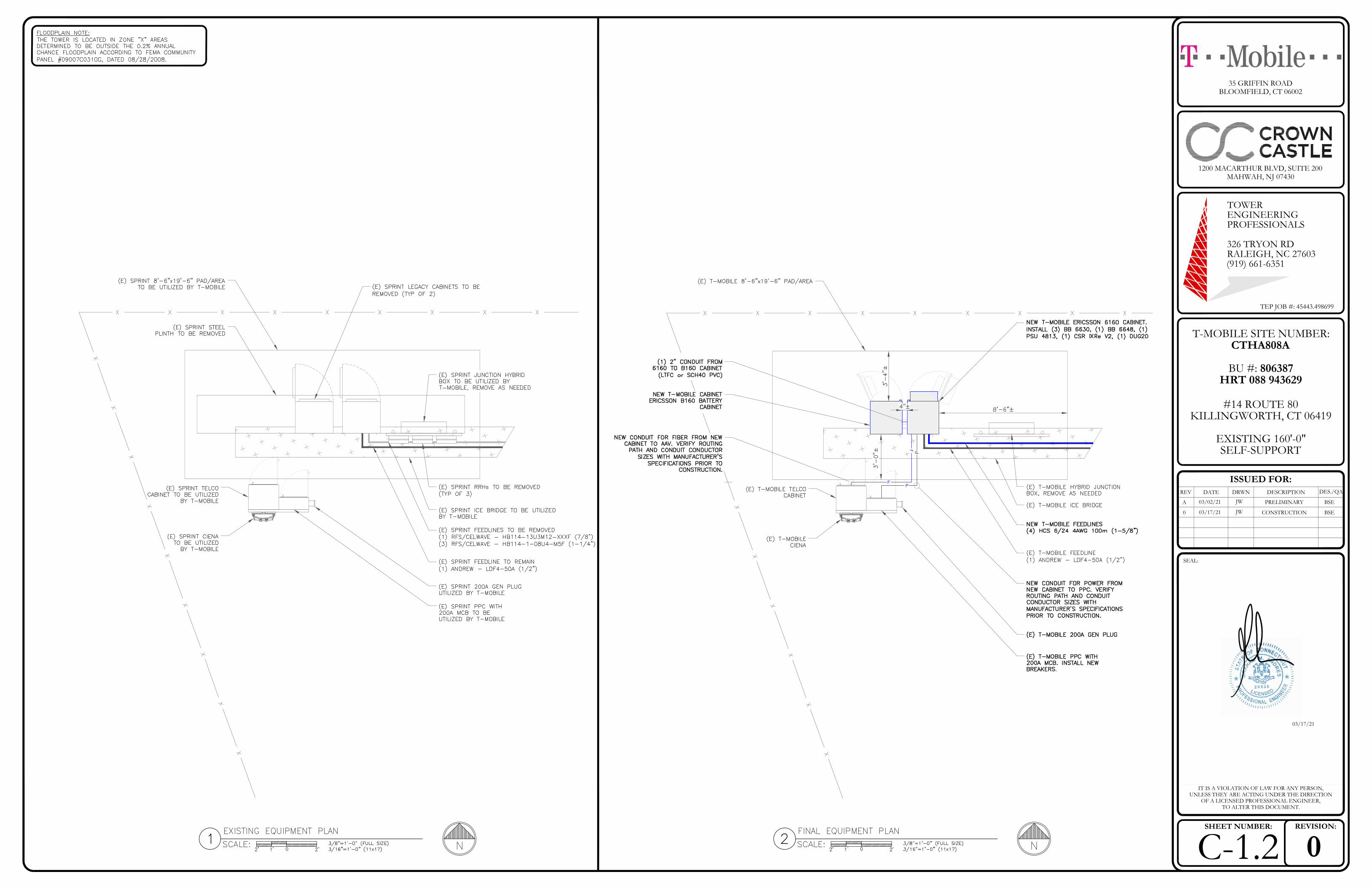
EXISTING & FINAL EQUIPMENT PLAN
ANTENNA & CABLE SCHEDULE
FINAL ELEVATION & ANTENNA PLANS
GENERAL NOTEST-2
ALL DRAWINGS CONTAINED HEREIN ARE FORMATTED FOR22x34. CONTRACTOR SHALL VERIFY ALL PLANS AND EXISTINGDIMENSIONS AND CONDITIONS ON THE JOB SITE AND SHALLIMMEDIATELY NOTIFY THE ENGINEER IN WRITING OF ANYDISCREPANCIES BEFORE PROCEEDING WITH THE WORK OR
BE RESPONSIBLE FOR SAME.
C-4 EQUIPMENT SPECS
E-1 AC PANEL SCHEDULES & ONE LINE DIAGRAM
G-1 ANTENNA GROUNDING DIAGRAM
G-2 GROUNDING DETAILS
G-3 GROUNDING DETAILS
CABINET SPECS
GRAHAM M. ANDRES - ELECTRICAL ENGINEER(919) 661-6351
C-5
V = 130 MPH (ULTIMATE 3 SECOND GUST)
0.171
WIND SPEED:
SEISMIC Ss:
BEXPOSURE CATEGORY:IIRISK CATEGORY:1TOPOGRAPHIC CATEGORY:
TIA-222-H / ASCE 7-16APPLICABLE CODES:
0.060SEISMIC S1:60 MPHSERVICE WIND SPEED:
THE PURPOSE OF THIS PROJECT IS TO ENHANCEBROADBAND CONNECTIVITY AND CAPACITY TO THEEXISTING ELIGIBLE WIRELESS FACILITY.
TOWER SCOPE OF WORK:· REMOVE (6) SPRINT ANTENNAS· REMOVE (12) SPRINT RRHs· REMOVE (4) SPRINT CABLES· REUSE (1) GPS & (1) 12" CABLE· REUSE (3) SECTOR MOUNTS· INSTALL (9) ANTENNAS· INSTALL (9) RRHs· INSTALL (4) HCS 6/24 4AWG 100m CABLES· INSTALL (6) BACK TO BACK RRH MOUNTS
GROUND SCOPE OF WORK:· REMOVE SPRINT CABINET(S), AS NEEDED· REUSE EXISTING SPRINT/NEXTEL PAD, ICE BRIDGE,
AND UTILITY EQUIPMENT· INSTALL (3) BB 6630, (1) BB 6648, (1) DUG20, (1) IXRE
ROUTER· INSTALL (1) PSU 4813 BOOSTER· INSTALL (2) CABINETS

IT IS A VIOLATION OF LAW FOR ANY PERSON,UNLESS THEY ARE ACTING UNDER THE DIRECTION
OF A LICENSED PROFESSIONAL ENGINEER,TO ALTER THIS DOCUMENT.
0T-2REVISION:SHEET NUMBER:
ISSUED FOR:
DRWNREV DESCRIPTION DES./QADATE
1200 MACARTHUR BLVD, SUITE 200MAHWAH, NJ 07430
T-MOBILE SITE NUMBER:CTHA808A
BU #: 806387HRT 088 943629
#14 ROUTE 80KILLINGWORTH, CT 06419
EXISTING 160'-0"SELF-SUPPORT
TOWERENGINEERINGPROFESSIONALS
326 TRYON RDRALEIGH, NC 27603(919) 661-6351
35 GRIFFIN ROADBLOOMFIELD, CT 06002
TEP JOB #: 45443.498699
A 03/02/21 JW BSEPRELIMINARY
03/17/21
SEAL:
0 03/17/21 JW BSECONSTRUCTION

IT IS A VIOLATION OF LAW FOR ANY PERSON,UNLESS THEY ARE ACTING UNDER THE DIRECTION
OF A LICENSED PROFESSIONAL ENGINEER,TO ALTER THIS DOCUMENT.
0C-1.1REVISION:SHEET NUMBER:
ISSUED FOR:
DRWNREV DESCRIPTION DES./QADATE
1200 MACARTHUR BLVD, SUITE 200MAHWAH, NJ 07430
T-MOBILE SITE NUMBER:CTHA808A
BU #: 806387HRT 088 943629
#14 ROUTE 80KILLINGWORTH, CT 06419
EXISTING 160'-0"SELF-SUPPORT
TOWERENGINEERINGPROFESSIONALS
326 TRYON RDRALEIGH, NC 27603(919) 661-6351
35 GRIFFIN ROADBLOOMFIELD, CT 06002
TEP JOB #: 45443.498699
A 03/02/21 JW BSEPRELIMINARY
03/17/21
SEAL:
0 03/17/21 JW BSECONSTRUCTION
IT IS A VIOLATION OF LAW FOR ANY PERSON,UNLESS THEY ARE ACTING UNDER THE DIRECTION
OF A LICENSED PROFESSIONAL ENGINEER,TO ALTER THIS DOCUMENT.
0C-1.2REVISION:SHEET NUMBER:
ISSUED FOR:
DRWNREV DESCRIPTION DES./QADATE
1200 MACARTHUR BLVD, SUITE 200MAHWAH, NJ 07430
T-MOBILE SITE NUMBER:CTHA808A
BU #: 806387HRT 088 943629
#14 ROUTE 80KILLINGWORTH, CT 06419
EXISTING 160'-0"SELF-SUPPORT
TOWERENGINEERINGPROFESSIONALS
326 TRYON RDRALEIGH, NC 27603(919) 661-6351
35 GRIFFIN ROADBLOOMFIELD, CT 06002
TEP JOB #: 45443.498699
A 03/02/21 JW BSEPRELIMINARY
03/17/21
SEAL:
0 03/17/21 JW BSECONSTRUCTION

IT IS A VIOLATION OF LAW FOR ANY PERSON,UNLESS THEY ARE ACTING UNDER THE DIRECTION
OF A LICENSED PROFESSIONAL ENGINEER,TO ALTER THIS DOCUMENT.
0C-2REVISION:SHEET NUMBER:
ISSUED FOR:
DRWNREV DESCRIPTION DES./QADATE
1200 MACARTHUR BLVD, SUITE 200MAHWAH, NJ 07430
T-MOBILE SITE NUMBER:CTHA808A
BU #: 806387HRT 088 943629
#14 ROUTE 80KILLINGWORTH, CT 06419
EXISTING 160'-0"SELF-SUPPORT
TOWERENGINEERINGPROFESSIONALS
326 TRYON RDRALEIGH, NC 27603(919) 661-6351
35 GRIFFIN ROADBLOOMFIELD, CT 06002
TEP JOB #: 45443.498699
A 03/02/21 JW BSEPRELIMINARY
03/17/21
SEAL:
0 03/17/21 JW BSECONSTRUCTION

IT IS A VIOLATION OF LAW FOR ANY PERSON,UNLESS THEY ARE ACTING UNDER THE DIRECTION
OF A LICENSED PROFESSIONAL ENGINEER,TO ALTER THIS DOCUMENT.
0C-3REVISION:SHEET NUMBER:
ISSUED FOR:
DRWNREV DESCRIPTION DES./QADATE
1200 MACARTHUR BLVD, SUITE 200MAHWAH, NJ 07430
T-MOBILE SITE NUMBER:CTHA808A
BU #: 806387HRT 088 943629
#14 ROUTE 80KILLINGWORTH, CT 06419
EXISTING 160'-0"SELF-SUPPORT
TOWERENGINEERINGPROFESSIONALS
326 TRYON RDRALEIGH, NC 27603(919) 661-6351
35 GRIFFIN ROADBLOOMFIELD, CT 06002
TEP JOB #: 45443.498699
A 03/02/21 JW BSEPRELIMINARY
03/17/21
SEAL:
0 03/17/21 JW BSECONSTRUCTION

IT IS A VIOLATION OF LAW FOR ANY PERSON,UNLESS THEY ARE ACTING UNDER THE DIRECTION
OF A LICENSED PROFESSIONAL ENGINEER,TO ALTER THIS DOCUMENT.
0C-4REVISION:SHEET NUMBER:
ISSUED FOR:
DRWNREV DESCRIPTION DES./QADATE
1200 MACARTHUR BLVD, SUITE 200MAHWAH, NJ 07430
T-MOBILE SITE NUMBER:CTHA808A
BU #: 806387HRT 088 943629
#14 ROUTE 80KILLINGWORTH, CT 06419
EXISTING 160'-0"SELF-SUPPORT
TOWERENGINEERINGPROFESSIONALS
326 TRYON RDRALEIGH, NC 27603(919) 661-6351
35 GRIFFIN ROADBLOOMFIELD, CT 06002
TEP JOB #: 45443.498699
A 03/02/21 JW BSEPRELIMINARY
03/17/21
SEAL:
0 03/17/21 JW BSECONSTRUCTION
ERICSSON
ERICSSON
ERICSSON

IT IS A VIOLATION OF LAW FOR ANY PERSON,UNLESS THEY ARE ACTING UNDER THE DIRECTION
OF A LICENSED PROFESSIONAL ENGINEER,TO ALTER THIS DOCUMENT.
0C-5REVISION:SHEET NUMBER:
ISSUED FOR:
DRWNREV DESCRIPTION DES./QADATE
1200 MACARTHUR BLVD, SUITE 200MAHWAH, NJ 07430
T-MOBILE SITE NUMBER:CTHA808A
BU #: 806387HRT 088 943629
#14 ROUTE 80KILLINGWORTH, CT 06419
EXISTING 160'-0"SELF-SUPPORT
TOWERENGINEERINGPROFESSIONALS
326 TRYON RDRALEIGH, NC 27603(919) 661-6351
35 GRIFFIN ROADBLOOMFIELD, CT 06002
TEP JOB #: 45443.498699
A 03/02/21 JW BSEPRELIMINARY
03/17/21
SEAL:
0 03/17/21 JW BSECONSTRUCTION
Width (A)
Height (B)
Depth (C)
Weight
Empty enclosure
650 mm / 25.5906 in
1450 mm / 57.08661 in (without base frame)
1600 mm / 62.99213 in (with base frame)
850 mm / 33.4646 in
176 kg / 388.014 lb
Dimensions
(B)
(A)
(C)

IT IS A VIOLATION OF LAW FOR ANY PERSON,UNLESS THEY ARE ACTING UNDER THE DIRECTION
OF A LICENSED PROFESSIONAL ENGINEER,TO ALTER THIS DOCUMENT.
0E-1REVISION:SHEET NUMBER:
ISSUED FOR:
DRWNREV DESCRIPTION DES./QADATE
1200 MACARTHUR BLVD, SUITE 200MAHWAH, NJ 07430
T-MOBILE SITE NUMBER:CTHA808A
BU #: 806387HRT 088 943629
#14 ROUTE 80KILLINGWORTH, CT 06419
EXISTING 160'-0"SELF-SUPPORT
TOWERENGINEERINGPROFESSIONALS
326 TRYON RDRALEIGH, NC 27603(919) 661-6351
35 GRIFFIN ROADBLOOMFIELD, CT 06002
TEP JOB #: 45443.498699
A 03/02/21 JW BSEPRELIMINARY
03/17/21
SEAL:
0 03/17/21 JW BSECONSTRUCTION

IT IS A VIOLATION OF LAW FOR ANY PERSON,UNLESS THEY ARE ACTING UNDER THE DIRECTION
OF A LICENSED PROFESSIONAL ENGINEER,TO ALTER THIS DOCUMENT.
0G-1REVISION:SHEET NUMBER:
ISSUED FOR:
DRWNREV DESCRIPTION DES./QADATE
1200 MACARTHUR BLVD, SUITE 200MAHWAH, NJ 07430
T-MOBILE SITE NUMBER:CTHA808A
BU #: 806387HRT 088 943629
#14 ROUTE 80KILLINGWORTH, CT 06419
EXISTING 160'-0"SELF-SUPPORT
TOWERENGINEERINGPROFESSIONALS
326 TRYON RDRALEIGH, NC 27603(919) 661-6351
35 GRIFFIN ROADBLOOMFIELD, CT 06002
TEP JOB #: 45443.498699
A 03/02/21 JW BSEPRELIMINARY
03/17/21
SEAL:
0 03/17/21 JW BSECONSTRUCTION
ICE BRIDGE/ EQUIPMENT POST:
ALL GROUNDS MUST ROUTE DOWNHILL FOR ENTIRE DURATION OF ROUTE
T-MOBILE GROUNDING NOTES:
PEDESTALS, PLINTHS, SSC CABINET, FCOA CABINETS:
ANTENNA/ COVP/ RRU MAST PIPES:
AIR TERMINALS:
TMA's, DIPLEXERS AND TRIPLEXERS:
ELEVATED STEEL PLATFORMS WITH LUNAR FEET:
STEEL CANOPY (STEEL PLATFORM OR CONCRETE PAD):
FSBE ALARM BOX:
SURGE SUPPRESSORS:
FYGA/FYGB BRACKET:
·
·
·
·
·
·
·
·
·
·
·

IT IS A VIOLATION OF LAW FOR ANY PERSON,UNLESS THEY ARE ACTING UNDER THE DIRECTION
OF A LICENSED PROFESSIONAL ENGINEER,TO ALTER THIS DOCUMENT.
0G-2REVISION:SHEET NUMBER:
ISSUED FOR:
DRWNREV DESCRIPTION DES./QADATE
1200 MACARTHUR BLVD, SUITE 200MAHWAH, NJ 07430
T-MOBILE SITE NUMBER:CTHA808A
BU #: 806387HRT 088 943629
#14 ROUTE 80KILLINGWORTH, CT 06419
EXISTING 160'-0"SELF-SUPPORT
TOWERENGINEERINGPROFESSIONALS
326 TRYON RDRALEIGH, NC 27603(919) 661-6351
35 GRIFFIN ROADBLOOMFIELD, CT 06002
TEP JOB #: 45443.498699
A 03/02/21 JW BSEPRELIMINARY
03/17/21
SEAL:
0 03/17/21 JW BSECONSTRUCTION

IT IS A VIOLATION OF LAW FOR ANY PERSON,UNLESS THEY ARE ACTING UNDER THE DIRECTION
OF A LICENSED PROFESSIONAL ENGINEER,TO ALTER THIS DOCUMENT.
0G-3REVISION:SHEET NUMBER:
ISSUED FOR:
DRWNREV DESCRIPTION DES./QADATE
1200 MACARTHUR BLVD, SUITE 200MAHWAH, NJ 07430
T-MOBILE SITE NUMBER:CTHA808A
BU #: 806387HRT 088 943629
#14 ROUTE 80KILLINGWORTH, CT 06419
EXISTING 160'-0"SELF-SUPPORT
TOWERENGINEERINGPROFESSIONALS
326 TRYON RDRALEIGH, NC 27603(919) 661-6351
35 GRIFFIN ROADBLOOMFIELD, CT 06002
TEP JOB #: 45443.498699
A 03/02/21 JW BSEPRELIMINARY
03/17/21
SEAL:
0 03/17/21 JW BSECONSTRUCTION

Exhibit D
Structural Analysis Report

Date: February 8, 2021 Tower Engineering Professionals 326 Tryon Road Raleigh, NC 27603 (919) 661-6351 Subject: Structural Analysis Report Carrier Designation: Sprint PCS Co-Locate Site Number: CTHA808A Site Name: CTHA808A Crown Castle Designation: BU Number: 806387 Site Name: HRT 088 943629 JDE Job Number: 628836 Work Order Number: 1918901 Order Number: 538771 Rev. 1 Engineering Firm Designation: TEP Project Number: 45443.495344 Site Data: #14 Route 80, Killingworth, Middlesex County, CT 06419 Latitude 41° 21' 26.43'', Longitude -72° 31' 11.83'' 160 Foot - Self-Supporting Tower Tower Engineering Professionals is pleased to submit this “Structural Analysis Report” to determine the structural integrity of the above-mentioned tower. The purpose of the analysis is to determine acceptability of the tower stress level. Based on our analysis we have determined the tower stress level for the structure and foundation, under the following load case, to be: LC5: Proposed Equipment Configuration Sufficient Capacity – 78.0% This analysis utilizes an ultimate 3-second gust wind speed of 130 mph as required by the 2018 Connecticut State Building Code. Applicable Standard references and design criteria are listed in Section 2 - Analysis Criteria. Structural analysis prepared by: Andrew Nearing / SH Respectfully submitted by: Shawn Hoffmeyer, P.E.

February 8, 2021 160-ft Self-Supporting Tower Structural Analysis Report CCI BU No 806387 TEP Project Number 45443.495344, Order 538771, Revision 1 Page 2
tnxTower Report - version 8.0.7.5
TABLE OF CONTENTS 1) INTRODUCTION 2) ANALYSIS CRITERIA Table 1 - Proposed Equipment Configuration Table 2 - Other Considered Equipment 3) ANALYSIS PROCEDURE Table 3 - Documents Provided 3.1) Analysis Method 3.2) Assumptions 4) ANALYSIS RESULTS Table 4 - Section Capacity (Summary) Table 5 - Tower Component Stresses vs. Capacity 4.1) Recommendations 5) APPENDIX A tnxTower Output 6) APPENDIX B Base Level Drawing 7) APPENDIX C Additional Calculations

February 8, 2021 160-ft Self-Supporting Tower Structural Analysis Report CCI BU No 806387 TEP Project Number 45443.495344, Order 538771, Revision 1 Page 3
tnxTower Report - version 8.0.7.5
1) INTRODUCTION This tower is a 160-ft monopole tower designed by Rohn. The tower has been modified multiple times in the past to accommodate additional loading. 2) ANALYSIS CRITERIA TIA-222 Revision: TIA-222-H Risk Category: II Wind Speed: 130 mph Exposure Category: B Topographic Factor: 1.0 Ice Thickness: 1.5 in Wind Speed with Ice: 50 mph Service Wind Speed: 60 mph
Table 1 - Proposed Equipment Configuration
Mounting Level (ft)
Center Line
Elevation (ft)
Number of
Antennas
Antenna Manufacturer
Antenna Model Number of Feed Lines
Feed Line
Size (in)
144.0 144.0
3 RFS Celwave APX16DWV-16DWV-S-E-A20
w/ Mount Pipe
4 1-5/8
3 RFS Celwave APXVAALL24_43-U-NA20_TMO
w/ Mount Pipe
3 Ericsson AIR6449 B41_T-MOBILE
w/ Mount Pipe
3 Ericsson RADIO 4415 B66A_CCIV3
3 Ericsson RADIO 4449 B71 B85A_T-MOBILE
3 Ericsson RADIO 4424 B25_TMO
1 Tower Mounts Sector Mount [SM 506-3]
50.0 50.0 1 Lucent KS24019-L112A
1 1/2 1 Tower Mounts Side Arm Mount [SO 306-1]
Table 2 - Other Considered Equipment
Mounting Level (ft)
Center Line
Elevation (ft)
Number of
Antennas
Antenna Manufacturer
Antenna Model Number of Feed Lines
Feed Line
Size (in)
157.0 157.0
6 Antel LPA-80080/6CF w/ Mount Pipe
1 8
1-5/8 7/8
6 Commscope JAHH-65B-R3B w/ Mount Pipe
3 Alcatel Lucent B66A RRH4X45
3 Nokia AHCA
1 Raycap RC3DC-3315-PF-48
3 Alcatel Lucent B13 RRH 4X30
3 SitePro Sector Mount [VFA12-HD]

February 8, 2021 160-ft Self-Supporting Tower Structural Analysis Report CCI BU No 806387 TEP Project Number 45443.495344, Order 538771, Revision 1 Page 4
tnxTower Report - version 8.0.7.5
Mounting Level (ft)
Center Line
Elevation (ft)
Number of
Antennas
Antenna Manufacturer
Antenna Model Number of Feed Lines
Feed Line
Size (in)
118.0 118.0
12 Decibel DB844H90E-XY w/ Mount Pipe
-- -- 1 Tower Mounts Sector Mount [SM 201-3]
1 Tower Mounts Pipe Mount [PM 601-3]
109.0 115.0 1 Celwave PD1110
1 1-1/4 109.0 1 Tower Mounts Side Arm Mount [SO 308-1]
90.0 90.0
6 Powerwave
Technologies 7770.00 w/ Mount Pipe
12 2 1
7/8 7/16 3/8
2 KMW Comm. AM-X-CD-16-65-00T-RET
w/ Mount Pipe
1 Powerwave
Technologies P45-16-XLH-RR w/ Mount Pipe
12 Powerwave
Technologies LGP21401
6 Ericsson RRUS-11
1 Raycap DC6-48-60-18-8F
1 Tower Mounts Sector Mount [SM 104-3]
3) ANALYSIS PROCEDURE
Table 3 - Documents Provided
Document Reference Source
Geotechnical Report 1237256 CCISites
Tower Foundation Drawings 821498 CCISites
Tower Manufacturer Drawings 2281721 CCISites
Tower Reinforcement Drawings 2221086 CCISites
Post-Modification Inspection 1296500 CCISites
Tower Reinforcement Drawings 2340021 CCISites
Post-Modification Inspection 2450760 CCISites
Tower Reinforcement Drawings 7235023 CCISites
Post-Modification Inspection 8150390 CCISites
3.1) Analysis Method
tnxTower (version 8.0.7.5), a commercially available analysis software package, was used to create a three-dimensional model of the tower and calculate member stresses for various loading cases. Selected output from the analysis is included in Appendix A. When applicable, Crown Castle has calculated and provided the effective area for panel antennas using approved methods following the intent of the TIA-222 Standard.

February 8, 2021 160-ft Self-Supporting Tower Structural Analysis Report CCI BU No 806387 TEP Project Number 45443.495344, Order 538771, Revision 1 Page 5
tnxTower Report - version 8.0.7.5
3.2) Assumptions
1) The tower and structures were maintained in accordance with the TIA-222 Standard. 2) The configuration of antennas, transmission cables, mounts and other appurtenances are as
specified in Tables 1 and 2, and the referenced drawings. This analysis may be affected if any assumptions are not valid or have been made in error. Tower Engineering Professionals should be notified to determine the effect on the structural integrity of the tower.
4) ANALYSIS RESULTS
Table 4 - Section Capacity (Summary)
Section No.
Elevation (ft)
Component Type Size Critical
Element P (kips) ΦPallow
(kips) %
Capacity Pass / Fail
T1 160 - 156 Leg Rohn 2.375'' x 0.218'' (2 EH) 3 -3.42 49.90 6.9 Pass
T2 156 - 152 Leg Rohn 2.375'' x 0.218'' (2 EH) 15 -4.23 52.40 8.1 Pass
T3 152 - 148 Leg Rohn 2.375'' x 0.218'' (2 EH) 24 -7.19 52.40 13.7 Pass
T4 148 - 144 Leg Rohn 2.375'' x 0.218'' (2 EH) 33 -10.33 52.40 19.7 Pass
T5 144 - 140 Leg Rohn 2.375'' x 0.218'' (2 EH) 42 -17.31 52.40 33.0 Pass
T6 140 - 120 Leg Rohn 2.875'' x 0.276'' (2.5 EH) 49 -49.60 78.15 63.5 Pass
T7 120 - 100 Leg ROHN 3 EH 79 -77.30 99.06 78.0 Pass
T8 100 - 80 Leg Rohn 4'' x 0.318'' (3.5 EH) (GR) 100 -104.94 155.70 67.4 Pass
T9 80 - 60 Leg ROHN 4 EH (GR) 121 -132.14 202.56 65.2 Pass
T10 60 - 40 Leg Rohn 5.563'' x 0.375'' (5 EH) (GR)
142 -155.68 259.31 60.0 Pass
T11 40 - 20 Leg Rohn 5.563'' x 0.375'' (5 EH) (GR)
157 -179.76 259.29 69.3 Pass
T12 20 - 0 Leg Rohn 6.625'' x 0.432'' (6 EH) (GR)
172 -203.21 400.17 50.8 Pass
T1 160 - 156 Diagonal L 1.5 x 1.5 x 1/8 9 -0.64 5.80 11.0 17.0 (b)
Pass
T2 156 - 152 Diagonal L 1.5 x 1.5 x 1/8 19 -1.85 5.79 32.0 51.2 (b)
Pass
T3 152 - 148 Diagonal L 1.5 x 1.5 x 1/8 27 -1.81 5.78 31.4 48.8 (b)
Pass
T4 148 - 144 Diagonal L 1.5 x 1.5 x 1/8 37 -1.96 5.77 34.1 54.9 (b)
Pass
T5 144 - 140 Diagonal L 2 x 2 x 1/4 45 -4.70 24.24 19.4 58.2 (b)
Pass
T6 140 - 120 Diagonal 2L 1.5 x 1.5 x 1/8 (3/16) 57 -3.72 14.33 26.0 63.1 (b)
Pass
T7 120 - 100 Diagonal 2L 2 x 2 x 3/16 (3/16) 84 -4.60 30.02 15.3 58.8 (b)
Pass
T8 100 - 80 Diagonal 2L 2.5 x 2.5 x 3/16 (3/16) 103 -5.56 40.83 13.6 41.7 (b)
Pass
T9 80 - 60 Diagonal 2L 3 x 3 x 3/16 (1/4) 124 -5.57 49.16 11.3 42.1 (b)
Pass
T10 60 - 40 Diagonal 2L 3 x 3 x 3/16 (1/4) 145 -6.52 37.89 17.2 40.1 (b)
Pass
T11 40 - 20 Diagonal 2L 3 x 3 x 1/4 (1/4) 161 -6.50 44.49 14.6 40.0 (b)
Pass
T12 20 - 0 Diagonal 2L 3.5 x 3.5 x 1/4 (1/4) 175 -7.27 57.93 12.5 43.6 (b)
Pass
T1 160 - 156 Top Girt L 2 x 2 x 1/8 4 -0.28 4.27 6.6 Pass
T6 140 - 120 Top Girt L 2 x 2 x 1/8 52 -0.67 4.27 15.6 Pass

February 8, 2021 160-ft Self-Supporting Tower Structural Analysis Report CCI BU No 806387 TEP Project Number 45443.495344, Order 538771, Revision 1 Page 6
tnxTower Report - version 8.0.7.5
Section No.
Elevation (ft)
Component Type Size Critical
Element P (kips) ΦPallow
(kips) %
Capacity Pass / Fail
17.1 (b)
Summary
Leg (T7) 78.0 Pass
Diagonal (T6)
63.1 Pass
Top Girt (T6)
17.1 Pass
Bolt Checks
63.1 Pass
RATING = 78.0 Pass
Table 5 - Tower Component Stresses vs. Capacity - LC5
Notes Component Elevation (ft) % Capacity Pass / Fail
1,2 Anchor Rods -- 27.1 Pass
1,2 Base Foundation Soil Interaction -- 56.8 Pass
1,2 Base Foundation Structural -- 30.4 Pass
Structure Rating (max from all components) = 78.0%
Notes: 1) See additional documentation in "Appendix C - Additional Calculations" for calculations supporting the % capacity listed. 2) Rating per TIA-222-H Section 15.5
4.1) Recommendations
1) The tower and its foundation have sufficient capacity to carry the proposed load configuration. No modifications are required at this time.

February 8, 2021 160-ft Self-Supporting Tower Structural Analysis Report CCI BU No 806387 TEP Project Number 45443.495344, Order 538771, Revision 1 Page 7
tnxTower Report - version 8.0.7.5
APPENDIX A
TNXTOWER OUTPUT

Tower Engineering Professionals
Tower Engineering Professionals 326 Tryon Road
Raleigh, NC 27603 Phone: (919) 661-6351 FAX: (919) 661-6350
Job: HRT 088 943629 (BU 806387) Project: TEP No. 45443.495344 Client: Crown Castle Drawn by: AN App'd:
Code: TIA-222-H Date: 02/08/21 Scale: NTS Path:
C:\Users\anearing\Desktop\45443\P-251573_L-495344_806387_HRT 088 943629_Structural Analysis\tnxTower\806387_1918901_LC5.eri
Dwg No. E-1
160.0 ft
156.0 ft
152.0 ft
148.0 ft
144.0 ft
140.0 ft
120.0 ft
100.0 ft
80.0 ft
60.0 ft
40.0 ft
20.0 ft
0.0 ft
REACTIONS - 130 mph WINDTORQUE 16 kip-ft
35 KSHEAR
3482 kip-ftMOMENT
49 KAXIAL
50 mph WIND - 1.50 in ICETORQUE 6 kip-ft
8 KSHEAR
803 kip-ftMOMENT
106 KAXIAL
SHEAR: 19 KUPLIFT: -172 K
SHEAR: 23 KDOWN: 209 K
MAX. CORNER REACTIONS AT BASE:
ARE FACTOREDALL REACTIONS
S
ect
ion
T1
T2
T3
T4
T5
T6
T7
T8
T9
T10
T11
T12
L
eg
sR
oh
n 2
.37
5"
x 0
.21
8"
(2 E
H)
Ro
hn
2.8
75
" x
0.2
76
" (2
.5 E
H)
RO
HN
3 E
HR
oh
n 4
" x
0.3
18
" (3
.5 E
H)
(GR
)R
OH
N 4
EH
(G
R)
Ro
hn
5.5
63
" x
0.3
75
" (5
E
H)
(GR
)A
L
eg
Gra
de
A5
72
-50
D
iag
on
als
L 1
.5 x
1.5
x 1
/8B
2L
1.5
x 1
.5 x
1/8
(3
/16
)2
L 2
x 2
x 3
/16
(3
/16
)2
L 2
.5 x
2.5
x 3
/16
(3
/16
)2
L 3
x 3
x 3
/16
(1
/4)
2L
3 x
3 x
1/4
(1
/4)
2L
3.5
x 3
.5 x
1/4
(1
/4)
D
iag
on
al G
rad
eA
36
CA
36
T
op
Gir
tsD
N.A
.L
2 x
2 x
1/8
N.A
.
F
ace
Wid
th (
ft)
6.5
20
83
6.5
29
17
6.5
37
56
.54
58
36
.55
41
76
.56
25
8.6
04
17
10
.63
54
12
.67
71
14
.77
08
16
.77
08
18
.85
42
20
.86
46
#
Pan
els
@ (
ft)
5 @
44
@ 5
9 @
6.6
66
67
6 @
10
W
eig
ht
(K)
0.2
0.1
0.1
0.1
0.2
1.0
1.6
2.8
3.7
4.2
4.9
6.6
25
.6
SYMBOL LISTMARK MARKSIZE SIZE
A Rohn 6.625" x 0.432" (6 EH) (GR)
B L 2 x 2 x 1/4
C A529-50
D L 2 x 2 x 1/8
MATERIAL STRENGTHGRADE GRADEFy FyFu Fu
A572-50 50 ksi 65 ksi
A36 36 ksi 58 ksi
A529-50 50 ksi 65 ksi
TOWER DESIGN NOTES1. Tower is located in Middlesex County, Connecticut.2. Tower designed for Exposure B to the TIA-222-H Standard.3. Tower designed for a 130 mph basic wind in accordance with the TIA-222-H Standard.4. Tower is also designed for a 50 mph basic wind with 1.50 in ice. Ice is considered to increase
in thickness with height.5. Deflections are based upon a 60 mph wind.6. Tower Risk Category II.7. Topographic Category 1 with Crest Height of 0.00 ft8. Grouted pipe f'c is 7 ksi9. TOWER RATING: 78%

ttnnxxTToowweerr Job
HRT 088 943629 (BU 806387)
Page
1 of 20
Tower Engineering
Professionals
326 Tryon Road
Project
TEP No. 45443.495344
Date
13:07:16 02/08/21
Raleigh, NC 27603
Phone: (919) 661-6351
FAX: (919) 661-6350
Client
Crown Castle Designed by
AN
Tower Input Data
The main tower is a 3x free standing tower with an overall height of 160.00 ft above the ground line.
The base of the tower is set at an elevation of 0.00 ft above the ground line.
The face width of the tower is 6.52 ft at the top and 20.86 ft at the base.
This tower is designed using the TIA-222-H standard.
The following design criteria apply:
Tower is located in Middlesex County, Connecticut.
Tower base elevation above sea level: 417.00 ft.
Basic wind speed of 130 mph.
Risk Category II.
Exposure Category B.
Simplified Topographic Factor Procedure for wind speed-up calculations is used.
Topographic Category: 1.
Crest Height: 0.00 ft.
Nominal ice thickness of 1.50 in.
Ice thickness is considered to increase with height.
Ice density of 56 pcf.
A wind speed of 50 mph is used in combination with ice.
Deflections calculated using a wind speed of 60 mph.
A non-linear (P-delta) analysis was used.
Grouted pipe f'c is 7 ksi.
Pressures are calculated at each section.
Tower analysis based on target reliabilities in accordance with Annex S.
Load Modification Factors used: Kes(Fw) = 0.95, Kes(ti) = 0.85.
Stress ratio used in tower member design is 1.05.
Local bending stresses due to climbing loads, feed line supports, and appurtenance mounts are not considered.
Options
Consider Moments - Legs Distribute Leg Loads As Uniform Use ASCE 10 X-Brace Ly Rules
Consider Moments - Horizontals Assume Legs Pinned √ Calculate Redundant Bracing Forces
Consider Moments - Diagonals √ Assume Rigid Index Plate Ignore Redundant Members in FEA
Use Moment Magnification √ Use Clear Spans For Wind Area √ SR Leg Bolts Resist Compression
Use Code Stress Ratios √ Use Clear Spans For KL/r All Leg Panels Have Same Allowable
√ Use Code Safety Factors - Guys √ Retension Guys To Initial Tension Offset Girt At Foundation
Escalate Ice √ Bypass Mast Stability Checks √ Consider Feed Line Torque
Always Use Max Kz √ Use Azimuth Dish Coefficients √ Include Angle Block Shear Check
Use Special Wind Profile √ Project Wind Area of Appurt. Use TIA-222-H Bracing Resist. Exemption
√ Include Bolts In Member Capacity Autocalc Torque Arm Areas Use TIA-222-H Tension Splice Exemption
Leg Bolts Are At Top Of Section Add IBC .6D+W Combination Poles
√ Secondary Horizontal Braces Leg √ Sort Capacity Reports By Component Include Shear-Torsion Interaction
Use Diamond Inner Bracing (4 Sided) Triangulate Diamond Inner Bracing Always Use Sub-Critical Flow
SR Members Have Cut Ends Treat Feed Line Bundles As Cylinder Use Top Mounted Sockets
SR Members Are Concentric Ignore KL/ry For 60 Deg. Angle Legs Pole Without Linear Attachments
Pole With Shroud Or No Appurtenances
Outside and Inside Corner Radii Are
Known

ttnnxxTToowweerr Job
HRT 088 943629 (BU 806387)
Page
2 of 20
Tower Engineering
Professionals
326 Tryon Road
Project
TEP No. 45443.495344
Date
13:07:16 02/08/21
Raleigh, NC 27603
Phone: (919) 661-6351
FAX: (919) 661-6350
Client
Crown Castle Designed by
AN
Tower Section Geometry
Tower
Section
Tower
Elevation
ft
Assembly
Database
Description Section
Width
ft
Number
of
Sections
Section
Length
ft
T1 160.00-156.00 6.52 1 4.00
T2 156.00-152.00 6.53 1 4.00
T3 152.00-148.00 6.54 1 4.00
T4 148.00-144.00 6.55 1 4.00
T5 144.00-140.00 6.55 1 4.00
T6 140.00-120.00 6.56 1 20.00
T7 120.00-100.00 8.60 1 20.00
T8 100.00-80.00 10.64 1 20.00
T9 80.00-60.00 12.68 1 20.00
T10 60.00-40.00 14.77 1 20.00
T11 40.00-20.00 16.77 1 20.00
T12 20.00-0.00 18.85 1 20.00
Tower Section Geometry (cont’d)
Tower
Section
Tower
Elevation
ft
Diagonal
Spacing
ft
Bracing
Type
Has
K Brace
End
Panels
Has
Horizontals
Top Girt
Offset
in
Bottom Girt
Offset
in
T1 160.00-156.00 4.00 X Brace No No 0.00 0.00
T2 156.00-152.00 4.00 X Brace No No 0.00 0.00
T3 152.00-148.00 4.00 X Brace No No 0.00 0.00
T4 148.00-144.00 4.00 X Brace No No 0.00 0.00
T5 144.00-140.00 4.00 X Brace No No 0.00 0.00
T6 140.00-120.00 5.00 X Brace No No 0.00 0.00
T7 120.00-100.00 6.67 X Brace No No 0.00 0.00
T8 100.00-80.00 6.67 X Brace No No 0.00 0.00
T9 80.00-60.00 6.67 X Brace No No 0.00 0.00
T10 60.00-40.00 10.00 X Brace No No 0.00 0.00
T11 40.00-20.00 10.00 X Brace No No 0.00 0.00
T12 20.00-0.00 10.00 X Brace No No 0.00 0.00
Tower Section Geometry (cont’d)
Tower
Elevation
ft
Leg
Type
Leg
Size
Leg
Grade
Diagonal
Type
Diagonal
Size
Diagonal
Grade
T1 160.00-156.00 Pipe Rohn 2.375'' x 0.218'' (2 EH) A572-50
(50 ksi)
Single Angle L 1.5 x 1.5 x 1/8 A36
(36 ksi)
T2 156.00-152.00 Pipe Rohn 2.375'' x 0.218'' (2 EH) A572-50
(50 ksi)
Single Angle L 1.5 x 1.5 x 1/8 A36
(36 ksi)
T3 152.00-148.00 Pipe Rohn 2.375'' x 0.218'' (2 EH) A572-50
(50 ksi)
Single Angle L 1.5 x 1.5 x 1/8 A36
(36 ksi)
T4 148.00-144.00 Pipe Rohn 2.375'' x 0.218'' (2 EH) A572-50
(50 ksi)
Single Angle L 1.5 x 1.5 x 1/8 A36
(36 ksi)
T5 144.00-140.00 Pipe Rohn 2.375'' x 0.218'' (2 EH) A572-50
(50 ksi)
Single Angle L 2 x 2 x 1/4 A529-50
(50 ksi)
T6 140.00-120.00 Pipe Rohn 2.875'' x 0.276'' (2.5 EH) A572-50
(50 ksi)
Double Angle 2L 1.5 x 1.5 x 1/8 (3/16) A36
(36 ksi)
T7 120.00-100.00 Pipe ROHN 3 EH A572-50 Double Angle 2L 2 x 2 x 3/16 (3/16) A36

ttnnxxTToowweerr Job
HRT 088 943629 (BU 806387)
Page
3 of 20
Tower Engineering
Professionals
326 Tryon Road
Project
TEP No. 45443.495344
Date
13:07:16 02/08/21
Raleigh, NC 27603
Phone: (919) 661-6351
FAX: (919) 661-6350
Client
Crown Castle Designed by
AN
Tower
Elevation
ft
Leg
Type
Leg
Size
Leg
Grade
Diagonal
Type
Diagonal
Size
Diagonal
Grade
(50 ksi) (36 ksi)
T8 100.00-80.00 Grouted Pipe Rohn 4'' x 0.318'' (3.5 EH) A572-50
(50 ksi)
Double Angle 2L 2.5 x 2.5 x 3/16 (3/16) A36
(36 ksi)
T9 80.00-60.00 Grouted Pipe ROHN 4 EH A572-50
(50 ksi)
Double Angle 2L 3 x 3 x 3/16 (1/4) A36
(36 ksi)
T10 60.00-40.00 Grouted Pipe Rohn 5.563'' x 0.375'' (5 EH) A572-50
(50 ksi)
Double Angle 2L 3 x 3 x 3/16 (1/4) A36
(36 ksi)
T11 40.00-20.00 Grouted Pipe Rohn 5.563'' x 0.375'' (5 EH) A572-50
(50 ksi)
Double Angle 2L 3 x 3 x 1/4 (1/4) A36
(36 ksi)
T12 20.00-0.00 Grouted Pipe Rohn 6.625'' x 0.432'' (6 EH) A572-50
(50 ksi)
Double Angle 2L 3.5 x 3.5 x 1/4 (1/4) A36
(36 ksi)
Tower Section Geometry (cont’d)
Tower
Elevation
ft
Top Girt
Type
Top Girt
Size
Top Girt
Grade
Bottom Girt
Type
Bottom Girt
Size
Bottom Girt
Grade
T1 160.00-156.00 Equal Angle L 2 x 2 x 1/8 A36
(36 ksi)
Single Angle A36
(36 ksi)
T6 140.00-120.00 Equal Angle L 2 x 2 x 1/8 A36
(36 ksi)
Single Angle A36
(36 ksi)
Tower Section Geometry (cont’d)
Tower
Elevation
ft
Gusset
Area
(per face)
ft2
Gusset
Thickness
in
Gusset Grade Adjust. Factor
Af
Adjust.
Factor
Ar
Weight Mult.
Double Angle
Stitch Bolt
Spacing
Diagonals
in
Double Angle
Stitch Bolt
Spacing
Horizontals
in
Double Angle
Stitch Bolt
Spacing
Redundants
in
T1
160.00-156.00
0.00 0.19 A36
(36 ksi)
1.03 1 1.05 30.00 30.00 36.00
T2
156.00-152.00
0.00 0.19 A36
(36 ksi)
1.03 1 1.05 30.00 30.00 36.00
T3
152.00-148.00
0.00 0.19 A36
(36 ksi)
1.03 1 1.05 30.00 30.00 36.00
T4
148.00-144.00
0.00 0.19 A36
(36 ksi)
1.03 1 1.05 30.00 30.00 36.00
T5
144.00-140.00
0.00 0.19 A36
(36 ksi)
1.03 1 1.05 30.00 30.00 36.00
T6
140.00-120.00
0.00 0.19 A36
(36 ksi)
1.03 1 1.05 Mid-Pt 30.00 36.00
T7
120.00-100.00
0.00 0.19 A36
(36 ksi)
1.03 1 1.05 Mid-Pt 30.00 36.00
T8
100.00-80.00
0.00 0.44 A36
(36 ksi)
1.03 1 1.05 Mid-Pt 30.00 36.00
T9 80.00-60.00 0.00 0.44 A36
(36 ksi)
1.03 1 1.05 Mid-Pt 30.00 36.00
T10
60.00-40.00
0.00 0.25 A36
(36 ksi)
1.03 1 1.05 Mid-Pt 30.00 36.00
T11
40.00-20.00
0.00 0.25 A36
(36 ksi)
1.03 1 1.05 Mid-Pt 30.00 36.00
T12 20.00-0.00 0.00 0.25 A36
(36 ksi)
1.03 1 1.05 Mid-Pt 30.00 36.00

ttnnxxTToowweerr Job
HRT 088 943629 (BU 806387)
Page
4 of 20
Tower Engineering
Professionals
326 Tryon Road
Project
TEP No. 45443.495344
Date
13:07:16 02/08/21
Raleigh, NC 27603
Phone: (919) 661-6351
FAX: (919) 661-6350
Client
Crown Castle Designed by
AN
Tower Section Geometry (cont’d)
K Factors1
Tower
Elevation
ft
Calc
K
Single
Angles
Calc
K
Solid
Rounds
Legs X
Brace
Diags
X
Y
K
Brace
Diags
X
Y
Single
Diags
X
Y
Girts
X
Y
Horiz.
X
Y
Sec.
Horiz.
X
Y
Inner
Brace
X
Y
T1
160.00-156.00
Yes No 1 1
1
1
1
1
1
1
1
1
1
1
1
1
1
T2
156.00-152.00
Yes No 1 1
1
1
1
1
1
1
1
1
1
1
1
1
1
T3
152.00-148.00
Yes No 1 1
1
1
1
1
1
1
1
1
1
1
1
1
1
T4
148.00-144.00
Yes No 1 1
1
1
1
1
1
1
1
1
1
1
1
1
1
T5
144.00-140.00
Yes No 1 1
1
1
1
1
1
1
1
1
1
1
1
1
1
T6
140.00-120.00
Yes No 1 1
1
1
1
1
1
1
1
1
1
1
1
1
1
T7
120.00-100.00
Yes No 1 1
1
1
1
1
1
1
1
1
1
1
1
1
1
T8
100.00-80.00
Yes No 1 1
1
1
1
1
1
1
1
1
1
1
1
1
1
T9
80.00-60.00
Yes No 1 1
1
1
1
1
1
1
1
1
1
1
1
1
1
T10
60.00-40.00
Yes No 1 1
1
1
1
1
1
1
1
1
1
1
1
1
1
T11
40.00-20.00
Yes No 1 1
1
1
1
1
1
1
1
1
1
1
1
1
1
T12
20.00-0.00
Yes No 1 1
1
1
1
1
1
1
1
1
1
1
1
1
1 1Note: K factors are applied to member segment lengths. K-braces without inner supporting members will have the K factor in the out-of-plane direction applied to
the overall length.
Tower Section Geometry (cont’d)
Tower
Elevation
ft
Leg Diagonal Top Girt Bottom Girt Mid Girt Long Horizontal Short Horizontal
Net Width
Deduct
in
U
Net Width
Deduct
in
U
Net Width
Deduct
in
U
Net
Width
Deduct
in
U
Net
Width
Deduct
in
U
Net
Width
Deduct
in
U
Net
Width
Deduct
in
U
T1
160.00-156.00
0.00 1 0.00 0.75 0.00 0.75 0.00 0.75 0.00 0.75 0.00 0.75 0.00 0.75
T2
156.00-152.00
0.00 1 0.00 0.75 0.00 0.75 0.00 0.75 0.00 0.75 0.00 0.75 0.00 0.75
T3
152.00-148.00
0.00 1 0.00 0.75 0.00 0.75 0.00 0.75 0.00 0.75 0.00 0.75 0.00 0.75
T4
148.00-144.00
0.00 1 0.00 0.75 0.00 0.75 0.00 0.75 0.00 0.75 0.00 0.75 0.00 0.75
T5
144.00-140.00
0.00 1 0.00 0.75 0.00 0.75 0.00 0.75 0.00 0.75 0.00 0.75 0.00 0.75
T6
140.00-120.00
0.00 1 0.00 0.75 0.00 0.75 0.00 0.75 0.00 0.75 0.00 0.75 0.00 0.75
T7
120.00-100.00
0.00 1 0.00 0.75 0.00 0.75 0.00 0.75 0.00 0.75 0.00 0.75 0.00 0.75
T8
100.00-80.00
0.00 1 0.00 0.75 0.00 0.75 0.00 0.75 0.00 0.75 0.00 0.75 0.00 0.75

ttnnxxTToowweerr Job
HRT 088 943629 (BU 806387)
Page
5 of 20
Tower Engineering
Professionals
326 Tryon Road
Project
TEP No. 45443.495344
Date
13:07:16 02/08/21
Raleigh, NC 27603
Phone: (919) 661-6351
FAX: (919) 661-6350
Client
Crown Castle Designed by
AN
Tower
Elevation
ft
Leg Diagonal Top Girt Bottom Girt Mid Girt Long Horizontal Short Horizontal
Net Width
Deduct
in
U
Net Width
Deduct
in
U
Net Width
Deduct
in
U
Net
Width
Deduct
in
U
Net
Width
Deduct
in
U
Net
Width
Deduct
in
U
Net
Width
Deduct
in
U
T9 80.00-60.00 0.00 1 0.00 0.75 0.00 0.75 0.00 0.75 0.00 0.75 0.00 0.75 0.00 0.75
T10
60.00-40.00
0.00 1 0.00 0.75 0.00 0.75 0.00 0.75 0.00 0.75 0.00 0.75 0.00 0.75
T11
40.00-20.00
0.00 1 0.00 0.75 0.00 0.75 0.00 0.75 0.00 0.75 0.00 0.75 0.00 0.75
T12 20.00-0.00 0.00 1 0.00 0.75 0.00 0.75 0.00 0.75 0.00 0.75 0.00 0.75 0.00 0.75
Tower Section Geometry (cont’d)
Tower
Elevation
ft
Connection Offsets
Diagonal K-Bracing
Vert.
Top
in
Horiz.
Top
in
Vert.
Bot.
in
Horiz.
Bot.
in
Vert.
Top
in
Horiz.
Top
in
Vert.
Bot.
in
Horiz.
Bot.
in
T1
160.00-156.00
2.50 3.50 2.50 3.50 0.00 0.00 0.00 0.00
T2
156.00-152.00
2.50 3.50 2.50 3.50 0.00 0.00 0.00 0.00
T3
152.00-148.00
2.50 3.50 2.50 3.50 0.00 0.00 0.00 0.00
T4
148.00-144.00
2.50 3.50 2.50 3.50 0.00 0.00 0.00 0.00
T5
144.00-140.00
2.50 3.50 2.50 3.50 0.00 0.00 0.00 0.00
T6
140.00-120.00
2.50 4.40 2.50 4.40 0.00 0.00 0.00 0.00
T7
120.00-100.00
2.50 4.90 2.50 4.90 0.00 0.00 0.00 0.00
T8
100.00-80.00
2.50 4.90 2.50 4.90 0.00 0.00 0.00 0.00
T9 80.00-60.00 2.50 4.80 2.50 4.80 0.00 0.00 0.00 0.00
T10
60.00-40.00
2.50 5.30 2.50 5.30 0.00 0.00 0.00 0.00
T11
40.00-20.00
2.50 5.40 2.50 5.40 0.00 0.00 0.00 0.00
T12 20.00-0.00 2.50 5.40 2.50 5.40 0.00 0.00 0.00 0.00
Tower Section Geometry (cont’d)
Tower
Elevation
ft
Leg
Connection
Type
Leg Diagonal Top Girt Bottom Girt Mid Girt Long Horizontal Short Horizontal
Bolt Size
in
No. Bolt Size
in
No. Bolt Size
in
No. Bolt Size
in
No. Bolt Size
in
No. Bolt Size
in
No. Bolt Size
in
No.
T1
160.00-156.00
Flange 0.63
A325N
4 0.50
A325N
1 0.50
A325N
1 0.00
A325N
0 0.63
A325N
0 0.63
A325N
0 0.63
A325N
0
T2
156.00-152.00
Flange 0.63
A325N
0 0.50
A325N
1 0.63
A325N
0 0.00
A325N
0 0.63
A325N
0 0.63
A325N
0 0.63
A325N
0

ttnnxxTToowweerr Job
HRT 088 943629 (BU 806387)
Page
6 of 20
Tower Engineering
Professionals
326 Tryon Road
Project
TEP No. 45443.495344
Date
13:07:16 02/08/21
Raleigh, NC 27603
Phone: (919) 661-6351
FAX: (919) 661-6350
Client
Crown Castle Designed by
AN
Tower
Elevation
ft
Leg
Connection
Type
Leg Diagonal Top Girt Bottom Girt Mid Girt Long Horizontal Short Horizontal
Bolt Size
in
No. Bolt Size
in
No. Bolt Size
in
No. Bolt Size
in
No. Bolt Size
in
No. Bolt Size
in
No. Bolt Size
in
No.
T3
152.00-148.00
Flange 0.63
A325N
0 0.50
A325N
1 0.63
A325N
0 0.00
A325N
0 0.63
A325N
0 0.63
A325N
0 0.63
A325N
0
T4
148.00-144.00
Flange 0.63
A325N
0 0.50
A325N
1 0.63
A325N
0 0.00
A325N
0 0.63
A325N
0 0.63
A325N
0 0.63
A325N
0
T5
144.00-140.00
Flange 0.63
A325N
0 0.50
A325N
1 0.63
A325N
0 0.63
A325N
0 0.63
A325N
0 0.63
A325N
0 0.63
A325N
0
T6
140.00-120.00
Flange 0.63
A325N
4 0.50
A325N
1 0.50
A325N
1 0.63
A325N
0 0.63
A325N
0 0.63
A325N
0 0.63
A325N
0
T7
120.00-100.00
Flange 0.75
A325N
4 0.50
A325N
1 0.63
A325N
0 0.63
A325N
0 0.63
A325N
0 0.63
A325N
0 0.63
A325N
0
T8
100.00-80.00
Flange 0.88
A325N
4 0.50
A325N
1 0.63
A325N
0 0.63
A325N
0 0.63
A325N
0 0.63
A325N
0 0.50
A325N
1
T9 80.00-60.00 Flange 1.00
A325N
6 0.50
A325N
1 0.63
A325N
0 0.63
A325N
0 0.63
A325N
0 0.63
A325N
0 0.50
A325N
1
T10
60.00-40.00
Flange 1.00
A325N
6 0.63
A325N
1 0.63
A325N
0 0.63
A325N
0 0.63
A325N
0 0.63
A325N
0 0.63
A325N
0
T11
40.00-20.00
Flange 1.00
A325N
6 0.63
A325N
1 0.63
A325N
0 0.63
A325N
0 0.63
A325N
0 0.63
A325N
0 0.50
A325N
1
T12 20.00-0.00 Flange 1.00
A449
6 0.63
A325N
1 0.63
A325N
0 0.63
A325N
0 0.63
A325N
0 0.63
A325N
0 0.63
A325N
0
Grouted Pipe Properties
Size Fy
ksi
As
in2
Ac
in2
Wt
plf
Ec
ksi
Em
ksi
Fym
ksi
Rohn 4'' x 0.318''
(3.5 EH) (GR)
50 3.68 8.89 31 4769 38218 64
ROHN 4 EH (GR) 50 4.41 11.50 39 4769 38952 66
Rohn 5.563'' x
0.375'' (5 EH) (GR)
50 6.11 18.19 59 4769 40357 68
Rohn 6.625'' x
0.432'' (6 EH) (GR)
50 8.40 26.07 83 4769 40832 68
Feed Line/Linear Appurtenances - Entered As Round Or Flat
Description Face
or
Leg
Allow
Shield
Exclude
From
Torque
Calculation
Component
Type
Placement
ft
Face
Offset
in
Lateral
Offset
(Frac FW)
# #
Per
Row
Clear
Spacing
in
Width or
Diameter
in
Perimeter
in
Weight
plf
**FACE A**
HB158-21U6S
24-xxM_TMO
(1-5/8)
A No No Ar (CaAa) 144.00 -
0.00
0.00 0.4 4 4 0.50 2.00 3
1.5'' flat Cable
Ladder Rail
A No No Af (CaAa) 150.00 -
0.00
0.00 0.42 1 1 12.00
1.50
1.50 2
***
**FACE B**
LDF5-50A(7/
8)
B No No Ar (CaAa) 157.00 -
0.00
0.00 0.45 8 8 0.50 1.09 0
HB158-1-08U
8-S8J18(1-5/8
)
B No No Ar (CaAa) 157.00 -
0.00
0.00 0.4 1 1 0.50 1.98 1

ttnnxxTToowweerr Job
HRT 088 943629 (BU 806387)
Page
7 of 20
Tower Engineering
Professionals
326 Tryon Road
Project
TEP No. 45443.495344
Date
13:07:16 02/08/21
Raleigh, NC 27603
Phone: (919) 661-6351
FAX: (919) 661-6350
Client
Crown Castle Designed by
AN
Description Face
or
Leg
Allow
Shield
Exclude
From
Torque
Calculation
Component
Type
Placement
ft
Face
Offset
in
Lateral
Offset
(Frac FW)
# #
Per
Row
Clear
Spacing
in
Width or
Diameter
in
Perimeter
in
Weight
plf
1.5'' flat Cable
Ladder Rail
B No No Af (CaAa) 160.00 -
0.00
0.00 0.42 1 1 12.00
1.50
1.50 2
***
**FACE C**
HB114-1-08U
4-M5F(1-1/4)
C No No Ar (CaAa) 109.00 -
0.00
0.00 -0.42 1 1 1.54 1.54 1
LDF4-50A(1/
2)
C No No Ar (CaAa) 50.00 - 0.00 0.00 -0.4 1 1 0.63 0.63 0
1.5'' flat Cable
Ladder Rail
C No No Af (CaAa) 150.00 -
0.00
0.00 -0.4 1 1 12.00
1.50
1.50 2
***
**LEG C**
LDF5-50A(7/
8'')
C No No Ar (CaAa) 90.00 - 0.00 -2.00 0.45 12 4 0.50 1.09 0
2'' (Nominal)
Conduit
C No No Ar (CaAa) 90.00 - 0.00 -2.00 0.45 1 1 2.38 2.38 1
FB-L98B-002-
75000(3/8)
C No No Ar (CaAa) 90.00 - 0.00 -2.00 0.45 1 1 0.39 0.39 0
WR-VG122S
T-BRDA(7/16
)
C No No Ar (CaAa) 90.00 - 0.00 -2.00 0.45 2 2 0.46 0.46 0
T-Brackets
(Af)
C No No Af (CaAa) 90.00 - 0.00 -2.00 0.45 1 1 1.00 1.00 8
***
Safety Line
3/8
B No No Ar (CaAa) 160.00 -
0.00
0.00 0.5 1 1 0.38 0.38 0
Step Peg
5/8''x8''x34''
step
A No No Ar (CaAa) 160.00 -
0.00
0.00 0.5 1 1 0.29 0.29 0
Step Peg
5/8''x8''x34''
step
B No No Ar (CaAa) 160.00 -
0.00
0.00 0.5 1 1 0.29 0.29 0
Step Peg
5/8''x8''x34''
step
C No No Ar (CaAa) 160.00 -
0.00
0.00 0.5 1 1 0.29 0.29 0
***
Discrete Tower Loads
Description Face
or
Leg
Offset
Type
Offsets:
Horz
Lateral
Vert
ft
ft
ft
Azimuth
Adjustment
°
Placement
ft
CAAA
Front
ft2
CAAA
Side
ft2
Weight
K
(2) LPA-80080/6CF w/
Mount Pipe
A From Leg 4.00
0.00
0.00
0.00 157.00 No Ice
1/2'' Ice
1'' Ice
2'' Ice
4.93
5.58
6.16
7.33
10.92
12.21
13.16
15.11
0.07
0.14
0.22
0.41
(2) LPA-80080/6CF w/
Mount Pipe
B From Leg 4.00
0.00
0.00
0.00 157.00 No Ice
1/2'' Ice
1'' Ice
2'' Ice
4.93
5.58
6.16
7.33
10.92
12.21
13.16
15.11
0.07
0.14
0.22
0.41
(2) LPA-80080/6CF w/
Mount Pipe
C From Leg 4.00
0.00
0.00
0.00 157.00 No Ice
1/2'' Ice
1'' Ice
4.93
5.58
6.16
10.92
12.21
13.16
0.07
0.14
0.22

ttnnxxTToowweerr Job
HRT 088 943629 (BU 806387)
Page
8 of 20
Tower Engineering
Professionals
326 Tryon Road
Project
TEP No. 45443.495344
Date
13:07:16 02/08/21
Raleigh, NC 27603
Phone: (919) 661-6351
FAX: (919) 661-6350
Client
Crown Castle Designed by
AN
Description Face
or
Leg
Offset
Type
Offsets:
Horz
Lateral
Vert
ft
ft
ft
Azimuth
Adjustment
°
Placement
ft
CAAA
Front
ft2
CAAA
Side
ft2
Weight
K
2'' Ice 7.33 15.11 0.41
(2) JAHH-65B-R3B w/
Mount Pipe
A From Leg 4.00
0.00
0.00
0.00 157.00 No Ice
1/2'' Ice
1'' Ice
2'' Ice
5.50
5.97
6.45
7.44
4.38
4.84
5.30
6.26
0.10
0.17
0.25
0.46
(2) JAHH-65B-R3B w/
Mount Pipe
B From Leg 4.00
0.00
0.00
0.00 157.00 No Ice
1/2'' Ice
1'' Ice
2'' Ice
5.50
5.97
6.45
7.44
4.38
4.84
5.30
6.26
0.10
0.17
0.25
0.46
(2) JAHH-65B-R3B w/
Mount Pipe
C From Leg 4.00
0.00
0.00
0.00 157.00 No Ice
1/2'' Ice
1'' Ice
2'' Ice
5.50
5.97
6.45
7.44
4.38
4.84
5.30
6.26
0.10
0.17
0.25
0.46
B66A RRH4X45 A From Leg 4.00
0.00
0.00
0.00 157.00 No Ice
1/2'' Ice
1'' Ice
2'' Ice
2.54
2.75
2.97
3.43
1.61
1.79
1.98
2.37
0.06
0.08
0.10
0.16
B66A RRH4X45 B From Leg 4.00
0.00
0.00
0.00 157.00 No Ice
1/2'' Ice
1'' Ice
2'' Ice
2.54
2.75
2.97
3.43
1.61
1.79
1.98
2.37
0.06
0.08
0.10
0.16
B66A RRH4X45 C From Leg 4.00
0.00
0.00
0.00 157.00 No Ice
1/2'' Ice
1'' Ice
2'' Ice
2.54
2.75
2.97
3.43
1.61
1.79
1.98
2.37
0.06
0.08
0.10
0.16
AHCA A From Leg 4.00
0.00
0.00
0.00 157.00 No Ice
1/2'' Ice
1'' Ice
2'' Ice
1.29
1.43
1.58
1.90
0.72
0.83
0.96
1.22
0.04
0.05
0.06
0.09
AHCA B From Leg 4.00
0.00
0.00
0.00 157.00 No Ice
1/2'' Ice
1'' Ice
2'' Ice
1.29
1.43
1.58
1.90
0.72
0.83
0.96
1.22
0.04
0.05
0.06
0.09
AHCA C From Leg 4.00
0.00
0.00
0.00 157.00 No Ice
1/2'' Ice
1'' Ice
2'' Ice
1.29
1.43
1.58
1.90
0.72
0.83
0.96
1.22
0.04
0.05
0.06
0.09
RC3DC-3315-PF-48 A From Leg 4.00
0.00
0.00
0.00 157.00 No Ice
1/2'' Ice
1'' Ice
2'' Ice
3.79
4.04
4.30
4.84
2.51
2.72
2.94
3.41
0.03
0.06
0.10
0.18
B13 RRH 4X30 A From Leg 4.00
0.00
0.00
0.00 157.00 No Ice
1/2'' Ice
1'' Ice
2'' Ice
2.06
2.24
2.43
2.84
1.32
1.48
1.64
2.00
0.06
0.07
0.09
0.14
B13 RRH 4X30 B From Leg 4.00
0.00
0.00
0.00 157.00 No Ice
1/2'' Ice
1'' Ice
2'' Ice
2.06
2.24
2.43
2.84
1.32
1.48
1.64
2.00
0.06
0.07
0.09
0.14
B13 RRH 4X30 C From Leg 4.00
0.00
0.00
0.00 157.00 No Ice
1/2'' Ice
1'' Ice
2'' Ice
2.06
2.24
2.43
2.84
1.32
1.48
1.64
2.00
0.06
0.07
0.09
0.14
Sitepro VFA12-HD Sector
Mount (3)
C None 0.00 157.00 No Ice
1/2'' Ice
1'' Ice
2'' Ice
25.20
38.36
51.52
77.84
25.20
38.36
51.52
77.84
1.97
2.41
2.85
3.73

ttnnxxTToowweerr Job
HRT 088 943629 (BU 806387)
Page
9 of 20
Tower Engineering
Professionals
326 Tryon Road
Project
TEP No. 45443.495344
Date
13:07:16 02/08/21
Raleigh, NC 27603
Phone: (919) 661-6351
FAX: (919) 661-6350
Client
Crown Castle Designed by
AN
Description Face
or
Leg
Offset
Type
Offsets:
Horz
Lateral
Vert
ft
ft
ft
Azimuth
Adjustment
°
Placement
ft
CAAA
Front
ft2
CAAA
Side
ft2
Weight
K
2.4'' Dia. x 6-ft A From Leg 4.00
0.00
0.00
0.00 157.00 No Ice
1/2'' Ice
1'' Ice
2'' Ice
1.43
1.92
2.29
3.06
1.43
1.92
2.29
3.06
0.02
0.03
0.05
0.09
2.4'' Dia. x 6-ft B From Leg 4.00
0.00
0.00
0.00 157.00 No Ice
1/2'' Ice
1'' Ice
2'' Ice
1.43
1.92
2.29
3.06
1.43
1.92
2.29
3.06
0.02
0.03
0.05
0.09
2.4'' Dia. x 6-ft C From Leg 4.00
0.00
0.00
0.00 157.00 No Ice
1/2'' Ice
1'' Ice
2'' Ice
1.43
1.92
2.29
3.06
1.43
1.92
2.29
3.06
0.02
0.03
0.05
0.09
***
APX16DWV-16DWV-S-E-A
20 w/ Mount Pipe
A From Leg 4.00
0.00
0.00
0.00 144.00 No Ice
1/2'' Ice
1'' Ice
2'' Ice
6.29
6.86
7.45
8.68
2.76
3.27
3.79
4.90
0.06
0.11
0.16
0.29
APX16DWV-16DWV-S-E-A
20 w/ Mount Pipe
B From Leg 4.00
0.00
0.00
0.00 144.00 No Ice
1/2'' Ice
1'' Ice
2'' Ice
6.29
6.86
7.45
8.68
2.76
3.27
3.79
4.90
0.06
0.11
0.16
0.29
APX16DWV-16DWV-S-E-A
20 w/ Mount Pipe
C From Leg 4.00
0.00
0.00
0.00 144.00 No Ice
1/2'' Ice
1'' Ice
2'' Ice
6.29
6.86
7.45
8.68
2.76
3.27
3.79
4.90
0.06
0.11
0.16
0.29
APXVAALL24_43-U-NA20
_TMO w/ Mount Pipe
A From Leg 4.00
0.00
0.00
0.00 144.00 No Ice
1/2'' Ice
1'' Ice
2'' Ice
14.69
15.46
16.23
17.82
6.87
7.55
8.25
9.67
0.18
0.31
0.45
0.78
APXVAALL24_43-U-NA20
_TMO w/ Mount Pipe
B From Leg 4.00
0.00
0.00
0.00 144.00 No Ice
1/2'' Ice
1'' Ice
2'' Ice
14.69
15.46
16.23
17.82
6.87
7.55
8.25
9.67
0.18
0.31
0.45
0.78
APXVAALL24_43-U-NA20
_TMO w/ Mount Pipe
C From Leg 4.00
0.00
0.00
0.00 144.00 No Ice
1/2'' Ice
1'' Ice
2'' Ice
14.69
15.46
16.23
17.82
6.87
7.55
8.25
9.67
0.18
0.31
0.45
0.78
AIR6449 B41_T-MOBILE
w/ Mount Pipe
A From Leg 4.00
0.00
0.00
0.00 144.00 No Ice
1/2'' Ice
1'' Ice
2'' Ice
5.87
6.23
6.61
7.38
3.27
3.73
4.20
5.20
0.13
0.18
0.23
0.36
AIR6449 B41_T-MOBILE
w/ Mount Pipe
B From Leg 4.00
0.00
0.00
0.00 144.00 No Ice
1/2'' Ice
1'' Ice
2'' Ice
5.87
6.23
6.61
7.38
3.27
3.73
4.20
5.20
0.13
0.18
0.23
0.36
AIR6449 B41_T-MOBILE
w/ Mount Pipe
C From Leg 4.00
0.00
0.00
0.00 144.00 No Ice
1/2'' Ice
1'' Ice
2'' Ice
5.87
6.23
6.61
7.38
3.27
3.73
4.20
5.20
0.13
0.18
0.23
0.36
RADIO 4415 B66A_CCIV3 A From Leg 4.00
0.00
0.00
0.00 144.00 No Ice
1/2'' Ice
1'' Ice
2'' Ice
1.64
1.80
1.97
2.32
0.68
0.79
0.91
1.18
0.05
0.06
0.07
0.11
RADIO 4415 B66A_CCIV3 B From Leg 4.00
0.00
0.00
0.00 144.00 No Ice
1/2'' Ice
1'' Ice
2'' Ice
1.64
1.80
1.97
2.32
0.68
0.79
0.91
1.18
0.05
0.06
0.07
0.11

ttnnxxTToowweerr Job
HRT 088 943629 (BU 806387)
Page
10 of 20
Tower Engineering
Professionals
326 Tryon Road
Project
TEP No. 45443.495344
Date
13:07:16 02/08/21
Raleigh, NC 27603
Phone: (919) 661-6351
FAX: (919) 661-6350
Client
Crown Castle Designed by
AN
Description Face
or
Leg
Offset
Type
Offsets:
Horz
Lateral
Vert
ft
ft
ft
Azimuth
Adjustment
°
Placement
ft
CAAA
Front
ft2
CAAA
Side
ft2
Weight
K
RADIO 4415 B66A_CCIV3 C From Leg 4.00
0.00
0.00
0.00 144.00 No Ice
1/2'' Ice
1'' Ice
2'' Ice
1.64
1.80
1.97
2.32
0.68
0.79
0.91
1.18
0.05
0.06
0.07
0.11
RADIO 4449 B71
B85A_T-MOBILE
A From Leg 4.00
0.00
0.00
0.00 144.00 No Ice
1/2'' Ice
1'' Ice
2'' Ice
1.97
2.15
2.33
2.72
1.59
1.75
1.92
2.28
0.07
0.09
0.12
0.17
RADIO 4449 B71
B85A_T-MOBILE
B From Leg 4.00
0.00
0.00
0.00 144.00 No Ice
1/2'' Ice
1'' Ice
2'' Ice
1.97
2.15
2.33
2.72
1.59
1.75
1.92
2.28
0.07
0.09
0.12
0.17
RADIO 4449 B71
B85A_T-MOBILE
C From Leg 4.00
0.00
0.00
0.00 144.00 No Ice
1/2'' Ice
1'' Ice
2'' Ice
1.97
2.15
2.33
2.72
1.59
1.75
1.92
2.28
0.07
0.09
0.12
0.17
RADIO 4424 B25_TMO A From Leg 4.00
0.00
0.00
0.00 144.00 No Ice
1/2'' Ice
1'' Ice
2'' Ice
2.05
2.23
2.42
2.81
1.61
1.77
1.94
2.30
0.09
0.11
0.13
0.19
RADIO 4424 B25_TMO B From Leg 4.00
0.00
0.00
0.00 144.00 No Ice
1/2'' Ice
1'' Ice
2'' Ice
2.05
2.23
2.42
2.81
1.61
1.77
1.94
2.30
0.09
0.11
0.13
0.19
RADIO 4424 B25_TMO C From Leg 4.00
0.00
0.00
0.00 144.00 No Ice
1/2'' Ice
1'' Ice
2'' Ice
2.05
2.23
2.42
2.81
1.61
1.77
1.94
2.30
0.09
0.11
0.13
0.19
Sector Mount [SM 506-3] C None 0.00 144.00 No Ice
1/2'' Ice
1'' Ice
2'' Ice
32.27
45.45
58.44
84.07
32.27
45.45
58.44
84.07
1.74
2.39
3.23
5.54
2.4'' Dia. x 6-ft A From Leg 4.00
0.00
0.00
0.00 144.00 No Ice
1/2'' Ice
1'' Ice
2'' Ice
1.43
1.92
2.29
3.06
1.43
1.92
2.29
3.06
0.02
0.03
0.05
0.09
2.4'' Dia. x 6-ft A From Leg 4.00
0.00
0.00
0.00 144.00 No Ice
1/2'' Ice
1'' Ice
2'' Ice
1.43
1.92
2.29
3.06
1.43
1.92
2.29
3.06
0.02
0.03
0.05
0.09
2.4'' Dia. x 6-ft A From Leg 4.00
0.00
0.00
0.00 144.00 No Ice
1/2'' Ice
1'' Ice
2'' Ice
1.43
1.92
2.29
3.06
1.43
1.92
2.29
3.06
0.02
0.03
0.05
0.09
***
(4) DB844H90E-XY w/
Mount Pipe
A From Leg 4.00
0.00
0.00
0.00 118.00 No Ice
1/2'' Ice
1'' Ice
2'' Ice
2.24
2.61
2.99
3.78
3.34
3.73
4.13
4.97
0.04
0.08
0.12
0.23
(4) DB844H90E-XY w/
Mount Pipe
B From Leg 4.00
0.00
0.00
0.00 118.00 No Ice
1/2'' Ice
1'' Ice
2'' Ice
2.24
2.61
2.99
3.78
3.34
3.73
4.13
4.97
0.04
0.08
0.12
0.23
(4) DB844H90E-XY w/
Mount Pipe
C From Leg 4.00
0.00
0.00
0.00 118.00 No Ice
1/2'' Ice
1'' Ice
2'' Ice
2.24
2.61
2.99
3.78
3.34
3.73
4.13
4.97
0.04
0.08
0.12
0.23

ttnnxxTToowweerr Job
HRT 088 943629 (BU 806387)
Page
11 of 20
Tower Engineering
Professionals
326 Tryon Road
Project
TEP No. 45443.495344
Date
13:07:16 02/08/21
Raleigh, NC 27603
Phone: (919) 661-6351
FAX: (919) 661-6350
Client
Crown Castle Designed by
AN
Description Face
or
Leg
Offset
Type
Offsets:
Horz
Lateral
Vert
ft
ft
ft
Azimuth
Adjustment
°
Placement
ft
CAAA
Front
ft2
CAAA
Side
ft2
Weight
K
Sector Mount [SM 201-3] C None 0.00 118.00 No Ice
1/2'' Ice
1'' Ice
2'' Ice
24.76
33.89
43.00
61.44
24.76
33.89
43.00
61.44
1.08
1.52
2.10
3.64
Pipe Mount [PM 601-3] C None 0.00 118.00 No Ice
1/2'' Ice
1'' Ice
2'' Ice
3.17
3.79
4.42
5.76
3.17
3.79
4.42
5.76
0.20
0.23
0.28
0.40
***
PD1110 C From Leg 0.00
0.00
6.00
0.00 109.00 No Ice
1/2'' Ice
1'' Ice
2'' Ice
2.50
3.84
5.20
7.97
2.50
3.84
5.20
7.97
0.02
0.04
0.07
0.15
Side Arm Mount [SO 308-1] C From Leg 0.00
0.00
0.00
0.00 109.00 No Ice
1/2'' Ice
1'' Ice
2'' Ice
0.41
0.81
1.23
2.09
3.06
5.10
7.20
11.96
0.05
0.08
0.12
0.25
***
(2) 7770.00 w/ Mount Pipe A From Leg 4.00
0.00
0.00
0.00 90.00 No Ice
1/2'' Ice
1'' Ice
2'' Ice
5.75
6.18
6.61
7.49
4.25
5.01
5.71
7.16
0.06
0.10
0.16
0.29
(2) 7770.00 w/ Mount Pipe B From Leg 4.00
0.00
0.00
0.00 90.00 No Ice
1/2'' Ice
1'' Ice
2'' Ice
5.75
6.18
6.61
7.49
4.25
5.01
5.71
7.16
0.06
0.10
0.16
0.29
(2) 7770.00 w/ Mount Pipe C From Leg 4.00
0.00
0.00
0.00 90.00 No Ice
1/2'' Ice
1'' Ice
2'' Ice
5.75
6.18
6.61
7.49
4.25
5.01
5.71
7.16
0.06
0.10
0.16
0.29
AM-X-CD-16-65-00T-RET
w/ Mount Pipe
A From Leg 4.00
0.00
0.00
0.00 90.00 No Ice
1/2'' Ice
1'' Ice
2'' Ice
4.63
5.06
5.51
6.43
3.27
3.69
4.12
5.00
0.07
0.13
0.20
0.38
AM-X-CD-16-65-00T-RET
w/ Mount Pipe
B From Leg 4.00
0.00
0.00
0.00 90.00 No Ice
1/2'' Ice
1'' Ice
2'' Ice
4.63
5.06
5.51
6.43
3.27
3.69
4.12
5.00
0.07
0.13
0.20
0.38
P45-16-XLH-RR w/ Mount
Pipe
C From Leg 4.00
0.00
0.00
0.00 90.00 No Ice
1/2'' Ice
1'' Ice
2'' Ice
8.24
8.70
9.16
10.09
4.83
5.57
6.27
7.67
0.04
0.10
0.17
0.34
(4) LGP21401 A From Leg 4.00
0.00
0.00
0.00 90.00 No Ice
1/2'' Ice
1'' Ice
2'' Ice
1.10
1.24
1.38
1.69
0.21
0.27
0.35
0.52
0.01
0.02
0.03
0.05
(4) LGP21401 B From Leg 4.00
0.00
0.00
0.00 90.00 No Ice
1/2'' Ice
1'' Ice
2'' Ice
1.10
1.24
1.38
1.69
0.21
0.27
0.35
0.52
0.01
0.02
0.03
0.05
(4) LGP21401 C From Leg 4.00
0.00
0.00
0.00 90.00 No Ice
1/2'' Ice
1'' Ice
2'' Ice
1.10
1.24
1.38
1.69
0.21
0.27
0.35
0.52
0.01
0.02
0.03
0.05
(2) RRUS-11 A From Leg 4.00
0.00
0.00
0.00 90.00 No Ice
1/2'' Ice
1'' Ice
2.79
3.00
3.21
1.19
1.34
1.50
0.05
0.07
0.10

ttnnxxTToowweerr Job
HRT 088 943629 (BU 806387)
Page
12 of 20
Tower Engineering
Professionals
326 Tryon Road
Project
TEP No. 45443.495344
Date
13:07:16 02/08/21
Raleigh, NC 27603
Phone: (919) 661-6351
FAX: (919) 661-6350
Client
Crown Castle Designed by
AN
Description Face
or
Leg
Offset
Type
Offsets:
Horz
Lateral
Vert
ft
ft
ft
Azimuth
Adjustment
°
Placement
ft
CAAA
Front
ft2
CAAA
Side
ft2
Weight
K
2'' Ice 3.67 1.84 0.15
(2) RRUS-11 B From Leg 4.00
0.00
0.00
0.00 90.00 No Ice
1/2'' Ice
1'' Ice
2'' Ice
2.79
3.00
3.21
3.67
1.19
1.34
1.50
1.84
0.05
0.07
0.10
0.15
(2) RRUS-11 C From Leg 4.00
0.00
0.00
0.00 90.00 No Ice
1/2'' Ice
1'' Ice
2'' Ice
2.79
3.00
3.21
3.67
1.19
1.34
1.50
1.84
0.05
0.07
0.10
0.15
DC6-48-60-18-8F C From Leg 4.00
0.00
0.00
0.00 90.00 No Ice
1/2'' Ice
1'' Ice
2'' Ice
1.21
1.89
2.11
2.57
1.21
1.89
2.11
2.57
0.03
0.05
0.08
0.14
Sector Mount [SM 104-3] C None 0.00 90.00 No Ice
1/2'' Ice
1'' Ice
2'' Ice
30.21
38.12
46.01
62.03
30.21
38.12
46.01
62.03
0.95
1.43
2.03
3.58
***
KS24019-L112A B From Leg 4.00
0.00
0.00
0.00 50.00 No Ice
1/2'' Ice
1'' Ice
2'' Ice
0.08
0.13
0.19
0.35
0.08
0.13
0.19
0.35
0.01
0.01
0.01
0.02
Side Arm Mount [SO 306-1] B From Leg 2.00
0.00
0.00
0.00 50.00 No Ice
1/2'' Ice
1'' Ice
2'' Ice
0.41
0.81
1.23
2.08
2.26
3.83
5.48
9.37
0.04
0.06
0.09
0.19
***
Load Combinations
Comb.
No.
Description
1 Dead Only
2 1.2 Dead+1.0 Wind 0 deg - No Ice
3 0.9 Dead+1.0 Wind 0 deg - No Ice
4 1.2 Dead+1.0 Wind 30 deg - No Ice
5 0.9 Dead+1.0 Wind 30 deg - No Ice
6 1.2 Dead+1.0 Wind 60 deg - No Ice
7 0.9 Dead+1.0 Wind 60 deg - No Ice
8 1.2 Dead+1.0 Wind 90 deg - No Ice
9 0.9 Dead+1.0 Wind 90 deg - No Ice
10 1.2 Dead+1.0 Wind 120 deg - No Ice
11 0.9 Dead+1.0 Wind 120 deg - No Ice
12 1.2 Dead+1.0 Wind 150 deg - No Ice
13 0.9 Dead+1.0 Wind 150 deg - No Ice
14 1.2 Dead+1.0 Wind 180 deg - No Ice
15 0.9 Dead+1.0 Wind 180 deg - No Ice
16 1.2 Dead+1.0 Wind 210 deg - No Ice
17 0.9 Dead+1.0 Wind 210 deg - No Ice
18 1.2 Dead+1.0 Wind 240 deg - No Ice
19 0.9 Dead+1.0 Wind 240 deg - No Ice
20 1.2 Dead+1.0 Wind 270 deg - No Ice
21 0.9 Dead+1.0 Wind 270 deg - No Ice
22 1.2 Dead+1.0 Wind 300 deg - No Ice

ttnnxxTToowweerr Job
HRT 088 943629 (BU 806387)
Page
13 of 20
Tower Engineering
Professionals
326 Tryon Road
Project
TEP No. 45443.495344
Date
13:07:16 02/08/21
Raleigh, NC 27603
Phone: (919) 661-6351
FAX: (919) 661-6350
Client
Crown Castle Designed by
AN
Comb.
No.
Description
23 0.9 Dead+1.0 Wind 300 deg - No Ice
24 1.2 Dead+1.0 Wind 330 deg - No Ice
25 0.9 Dead+1.0 Wind 330 deg - No Ice
26 1.2 Dead+1.0 Ice
27 1.2 Dead+1.0 Wind 0 deg+1.0 Ice
28 1.2 Dead+1.0 Wind 30 deg+1.0 Ice
29 1.2 Dead+1.0 Wind 60 deg+1.0 Ice
30 1.2 Dead+1.0 Wind 90 deg+1.0 Ice
31 1.2 Dead+1.0 Wind 120 deg+1.0 Ice
32 1.2 Dead+1.0 Wind 150 deg+1.0 Ice
33 1.2 Dead+1.0 Wind 180 deg+1.0 Ice
34 1.2 Dead+1.0 Wind 210 deg+1.0 Ice
35 1.2 Dead+1.0 Wind 240 deg+1.0 Ice
36 1.2 Dead+1.0 Wind 270 deg+1.0 Ice
37 1.2 Dead+1.0 Wind 300 deg+1.0 Ice
38 1.2 Dead+1.0 Wind 330 deg+1.0 Ice
39 Dead+Wind 0 deg - Service
40 Dead+Wind 30 deg - Service
41 Dead+Wind 60 deg - Service
42 Dead+Wind 90 deg - Service
43 Dead+Wind 120 deg - Service
44 Dead+Wind 150 deg - Service
45 Dead+Wind 180 deg - Service
46 Dead+Wind 210 deg - Service
47 Dead+Wind 240 deg - Service
48 Dead+Wind 270 deg - Service
49 Dead+Wind 300 deg - Service
50 Dead+Wind 330 deg - Service
Maximum Reactions
Location Condition Gov.
Load
Comb.
Vertical
K
Horizontal, X
K
Horizontal, Z
K
Leg C Max. Vert 18 209.13 19.77 -11.02
Max. Hx 18 209.13 19.77 -11.02
Max. Hz 7 -172.22 -16.63 9.19
Min. Vert 7 -172.22 -16.63 9.19
Min. Hx 7 -172.22 -16.63 9.19
Min. Hz 18 209.13 19.77 -11.02
Leg B Max. Vert 10 207.48 -19.41 -11.30
Max. Hx 23 -170.93 16.27 9.49
Max. Hz 23 -170.93 16.27 9.49
Min. Vert 23 -170.93 16.27 9.49
Min. Hx 10 207.48 -19.41 -11.30
Min. Hz 10 207.48 -19.41 -11.30
Leg A Max. Vert 2 205.52 0.14 22.20
Max. Hx 21 12.47 2.07 1.02
Max. Hz 2 205.52 0.14 22.20
Min. Vert 15 -168.48 -0.15 -18.56
Min. Hx 9 12.36 -2.07 1.03
Min. Hz 15 -168.48 -0.15 -18.56

ttnnxxTToowweerr Job
HRT 088 943629 (BU 806387)
Page
14 of 20
Tower Engineering
Professionals
326 Tryon Road
Project
TEP No. 45443.495344
Date
13:07:16 02/08/21
Raleigh, NC 27603
Phone: (919) 661-6351
FAX: (919) 661-6350
Client
Crown Castle Designed by
AN
Tower Mast Reaction Summary
Load
Combination
Vertical
K
Shearx
K
Shearz
K
Overturning
Moment, Mx kip-ft
Overturning
Moment, Mz kip-ft
Torque
kip-ft
Dead Only 41.06 -0.00 0.00 -1.73 1.84 -0.00
1.2 Dead+1.0 Wind 0 deg - No
Ice
49.27 0.00 -34.40 -3416.79 3.12 5.31
0.9 Dead+1.0 Wind 0 deg - No
Ice
36.95 0.00 -34.40 -3412.32 2.57 5.31
1.2 Dead+1.0 Wind 30 deg - No
Ice
49.27 16.63 -28.86 -2899.91 -1666.28 15.87
0.9 Dead+1.0 Wind 30 deg - No
Ice
36.95 16.63 -28.86 -2896.02 -1664.89 15.88
1.2 Dead+1.0 Wind 60 deg - No
Ice
49.27 28.73 -16.62 -1674.35 -2887.77 12.62
0.9 Dead+1.0 Wind 60 deg - No
Ice
36.95 28.73 -16.62 -1671.88 -2884.96 12.63
1.2 Dead+1.0 Wind 90 deg - No
Ice
49.27 34.29 -0.00 -1.37 -3423.24 2.73
0.9 Dead+1.0 Wind 90 deg - No
Ice
36.95 34.29 -0.00 -0.83 -3419.82 2.73
1.2 Dead+1.0 Wind 120 deg -
No Ice
49.27 30.18 17.45 1729.12 -2988.02 -2.96
0.9 Dead+1.0 Wind 120 deg -
No Ice
36.95 30.18 17.46 1727.66 -2985.12 -2.95
1.2 Dead+1.0 Wind 150 deg -
No Ice
49.27 16.32 28.34 2843.98 -1637.05 -1.11
0.9 Dead+1.0 Wind 150 deg -
No Ice
36.95 16.32 28.34 2841.21 -1635.70 -1.11
1.2 Dead+1.0 Wind 180 deg -
No Ice
49.27 -0.00 32.46 3270.21 1.20 -5.31
0.9 Dead+1.0 Wind 180 deg -
No Ice
36.95 -0.00 32.46 3266.93 0.65 -5.31
1.2 Dead+1.0 Wind 210 deg -
No Ice
49.27 -16.63 28.86 2895.96 1670.22 -15.87
0.9 Dead+1.0 Wind 210 deg -
No Ice
36.95 -16.63 28.86 2893.12 1667.74 -15.88
1.2 Dead+1.0 Wind 240 deg -
No Ice
49.27 -30.41 17.59 1741.38 3015.42 -12.62
0.9 Dead+1.0 Wind 240 deg -
No Ice
36.95 -30.41 17.59 1739.90 3011.40 -12.63
1.2 Dead+1.0 Wind 270 deg -
No Ice
49.27 -34.29 0.01 -3.29 3427.63 -2.73
0.9 Dead+1.0 Wind 270 deg -
No Ice
36.95 -34.29 0.01 -2.76 3423.12 -2.73
1.2 Dead+1.0 Wind 300 deg -
No Ice
49.27 -28.49 -16.48 -1662.22 2869.08 2.96
0.9 Dead+1.0 Wind 300 deg -
No Ice
36.95 -28.49 -16.48 -1659.75 2865.20 2.95
1.2 Dead+1.0 Wind 330 deg -
No Ice
49.27 -16.32 -28.34 -2848.04 1641.72 1.11
0.9 Dead+1.0 Wind 330 deg -
No Ice
36.95 -16.32 -28.34 -2844.20 1639.27 1.11
1.2 Dead+1.0 Ice 105.64 -0.00 0.00 11.94 -11.83 0.00
1.2 Dead+1.0 Wind 0 deg+1.0
Ice
105.64 -0.00 -7.97 -758.78 -11.05 3.08
1.2 Dead+1.0 Wind 30 deg+1.0
Ice
105.64 3.96 -6.89 -656.84 -396.12 5.84
1.2 Dead+1.0 Wind 60 deg+1.0
Ice
105.64 6.97 -4.03 -379.48 -688.54 5.65
1.2 Dead+1.0 Wind 90 deg+1.0
Ice
105.64 8.13 0.00 13.01 -798.94 1.93
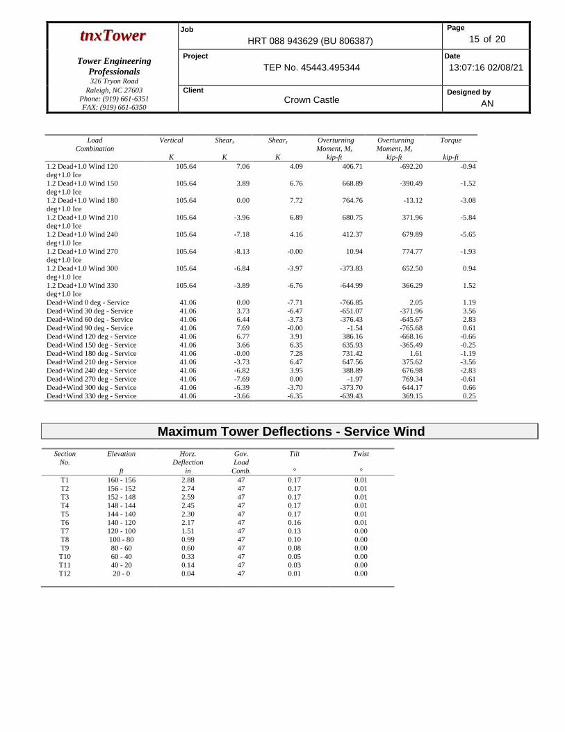
ttnnxxTToowweerr Job
HRT 088 943629 (BU 806387)
Page
15 of 20
Tower Engineering
Professionals
326 Tryon Road
Project
TEP No. 45443.495344
Date
13:07:16 02/08/21
Raleigh, NC 27603
Phone: (919) 661-6351
FAX: (919) 661-6350
Client
Crown Castle Designed by
AN
Load
Combination
Vertical
K
Shearx
K
Shearz
K
Overturning
Moment, Mx kip-ft
Overturning
Moment, Mz kip-ft
Torque
kip-ft
1.2 Dead+1.0 Wind 120
deg+1.0 Ice
105.64 7.06 4.09 406.71 -692.20 -0.94
1.2 Dead+1.0 Wind 150
deg+1.0 Ice
105.64 3.89 6.76 668.89 -390.49 -1.52
1.2 Dead+1.0 Wind 180
deg+1.0 Ice
105.64 0.00 7.72 764.76 -13.12 -3.08
1.2 Dead+1.0 Wind 210
deg+1.0 Ice
105.64 -3.96 6.89 680.75 371.96 -5.84
1.2 Dead+1.0 Wind 240
deg+1.0 Ice
105.64 -7.18 4.16 412.37 679.89 -5.65
1.2 Dead+1.0 Wind 270
deg+1.0 Ice
105.64 -8.13 -0.00 10.94 774.77 -1.93
1.2 Dead+1.0 Wind 300
deg+1.0 Ice
105.64 -6.84 -3.97 -373.83 652.50 0.94
1.2 Dead+1.0 Wind 330
deg+1.0 Ice
105.64 -3.89 -6.76 -644.99 366.29 1.52
Dead+Wind 0 deg - Service 41.06 0.00 -7.71 -766.85 2.05 1.19
Dead+Wind 30 deg - Service 41.06 3.73 -6.47 -651.07 -371.96 3.56
Dead+Wind 60 deg - Service 41.06 6.44 -3.73 -376.43 -645.67 2.83
Dead+Wind 90 deg - Service 41.06 7.69 -0.00 -1.54 -765.68 0.61
Dead+Wind 120 deg - Service 41.06 6.77 3.91 386.16 -668.16 -0.66
Dead+Wind 150 deg - Service 41.06 3.66 6.35 635.93 -365.49 -0.25
Dead+Wind 180 deg - Service 41.06 -0.00 7.28 731.42 1.61 -1.19
Dead+Wind 210 deg - Service 41.06 -3.73 6.47 647.56 375.62 -3.56
Dead+Wind 240 deg - Service 41.06 -6.82 3.95 388.89 676.98 -2.83
Dead+Wind 270 deg - Service 41.06 -7.69 0.00 -1.97 769.34 -0.61
Dead+Wind 300 deg - Service 41.06 -6.39 -3.70 -373.70 644.17 0.66
Dead+Wind 330 deg - Service 41.06 -3.66 -6.35 -639.43 369.15 0.25
Maximum Tower Deflections - Service Wind
Section
No.
Elevation
ft
Horz.
Deflection
in
Gov.
Load
Comb.
Tilt
°
Twist
°
T1 160 - 156 2.88 47 0.17 0.01
T2 156 - 152 2.74 47 0.17 0.01
T3 152 - 148 2.59 47 0.17 0.01
T4 148 - 144 2.45 47 0.17 0.01
T5 144 - 140 2.30 47 0.17 0.01
T6 140 - 120 2.17 47 0.16 0.01
T7 120 - 100 1.51 47 0.13 0.00
T8 100 - 80 0.99 47 0.10 0.00
T9 80 - 60 0.60 47 0.08 0.00
T10 60 - 40 0.33 47 0.05 0.00
T11 40 - 20 0.14 47 0.03 0.00
T12 20 - 0 0.04 47 0.01 0.00

ttnnxxTToowweerr Job
HRT 088 943629 (BU 806387)
Page
16 of 20
Tower Engineering
Professionals
326 Tryon Road
Project
TEP No. 45443.495344
Date
13:07:16 02/08/21
Raleigh, NC 27603
Phone: (919) 661-6351
FAX: (919) 661-6350
Client
Crown Castle Designed by
AN
Critical Deflections and Radius of Curvature - Service Wind
Elevation
ft
Appurtenance Gov.
Load
Comb.
Deflection
in
Tilt
°
Twist
°
Radius of
Curvature
ft
157.00 (2) LPA-80080/6CF w/ Mount Pipe 47 2.77 0.17 0.01 67191
144.00 APX16DWV-16DWV-S-E-A20 w/
Mount Pipe
47 2.30 0.17 0.01 73012
118.00 (4) DB844H90E-XY w/ Mount Pipe 47 1.45 0.13 0.00 29254
109.00 PD1110 47 1.20 0.12 0.00 32112
90.00 (2) 7770.00 w/ Mount Pipe 47 0.78 0.09 0.00 38869
50.00 KS24019-L112A 47 0.23 0.04 0.00 59379
Bolt Design Data
Section
No.
Elevation
ft
Component
Type
Bolt
Grade
Bolt Size
in
Number
Of
Bolts
Maximum
Load
per Bolt
K
Allowable
Load
per Bolt
K
Ratio
Load
Allowable
Allowable
Ratio
Criteria
T1 160 Leg A325N 0.63 4 0.29 20.34 0.014 1 Bolt Tension
Diagonal A325N 0.50 1 0.62 3.47 0.178 1.05 Member Block
Shear
Top Girt A325N 0.50 1 0.29 4.13 0.069 1.05 Member Bearing
T2 156 Diagonal A325N 0.50 1 1.86 3.47 0.537 1.05 Member Block
Shear
T3 152 Diagonal A325N 0.50 1 1.78 3.47 0.512 1.05 Member Block
Shear
T4 148 Diagonal A325N 0.50 1 2.00 3.47 0.577 1.05 Member Block
Shear
T5 144 Diagonal A325N 0.50 1 4.58 7.50 0.611 1.05 Gusset Bearing
T6 140 Leg A325N 0.63 4 10.62 20.34 0.522 1.05 Bolt Tension
Diagonal A325N 0.50 1 4.14 6.25 0.662 1.05 Member Block
Shear
Top Girt A325N 0.50 1 0.74 4.13 0.180 1.05 Member Bearing
T7 120 Leg A325N 0.75 4 16.73 30.10 0.556 1.05 Bolt Tension
Diagonal A325N 0.50 1 4.64 7.50 0.618 1.05 Gusset Bearing
T8 100 Leg A325N 0.88 4 22.48 41.56 0.541 1.05 Bolt Tension
Diagonal A325N 0.50 1 5.43 12.40 0.438 1.05 Member Bearing
T9 80 Leg A325N 1.00 6 18.80 54.52 0.345 1.05 Bolt Tension
Diagonal A325N 0.50 1 5.48 12.40 0.442 1.05 Member Bearing
T10 60 Leg A325N 1.00 6 22.02 54.52 0.404 1.05 Bolt Tension
Diagonal A325N 0.63 1 6.22 14.79 0.421 1.05 Gusset Bearing
T11 40 Leg A325N 1.00 6 25.15 54.52 0.461 1.05 Bolt Tension
Diagonal A325N 0.63 1 6.21 14.79 0.420 1.05 Gusset Bearing
T12 20 Leg A449 1.00 6 28.01 54.52 0.514 1.05 Bolt Tension
Diagonal A325N 0.63 1 6.77 14.79 0.458 1.05 Gusset Bearing

ttnnxxTToowweerr Job
HRT 088 943629 (BU 806387)
Page
17 of 20
Tower Engineering
Professionals
326 Tryon Road
Project
TEP No. 45443.495344
Date
13:07:16 02/08/21
Raleigh, NC 27603
Phone: (919) 661-6351
FAX: (919) 661-6350
Client
Crown Castle Designed by
AN
Compression Checks
Leg Design Data (Compression)
Section
No.
Elevation
ft
Size
L
ft
Lu
ft
Kl/r
A
in2
Pu
K
Pn
K
Ratio
Pu
Pn
T1 160 - 156 Rohn 2.375'' x 0.218'' (2 EH) 4.00 4.00 62.6
K=1.00
1.48 -3.42 49.90 0.069*1
T2 156 - 152 Rohn 2.375'' x 0.218'' (2 EH) 4.00 4.00 62.6
K=1.00
1.48 -4.23 49.90 0.085 1
T3 152 - 148 Rohn 2.375'' x 0.218'' (2 EH) 4.00 4.00 62.6
K=1.00
1.48 -7.19 49.90 0.144 1
T4 148 - 144 Rohn 2.375'' x 0.218'' (2 EH) 4.00 4.00 62.6
K=1.00
1.48 -10.33 49.90 0.207 1
T5 144 - 140 Rohn 2.375'' x 0.218'' (2 EH) 4.00 4.00 62.6
K=1.00
1.48 -17.31 49.90 0.347 1
T6 140 - 120 Rohn 2.875'' x 0.276'' (2.5
EH)
20.03 5.01 65.0
K=1.00
2.25 -49.60 74.43 0.666 1
T7 120 - 100 ROHN 3 EH 20.03 6.68 70.5
K=1.00
3.02 -77.30 94.34 0.819 1
T8 100 - 80 Rohn 4'' x 0.318'' (3.5 EH)
(GR)
20.03 6.68 61.3
K=1.00
3.68 -104.94 148.29 0.708 1
T9 80 - 60 ROHN 4 EH (GR) 20.04 6.68 54.3
K=1.00
4.41 -132.14 192.91 0.685 1
T10 60 - 40 Rohn 5.563'' x 0.375'' (5
EH) (GR)
20.03 10.02 65.4
K=1.00
6.11 -155.68 246.97 0.630 1
T11 40 - 20 Rohn 5.563'' x 0.375'' (5
EH) (GR)
20.04 10.02 65.4
K=1.00
6.11 -179.76 246.94 0.728 1
T12 20 - 0 Rohn 6.625'' x 0.432'' (6 EH)
(GR)
20.03 10.02 54.8
K=1.00
8.40 -203.21 381.11 0.533 1
* DL controls 1 P u / Pn controls
Diagonal Design Data (Compression)
Section
No.
Elevation
ft
Size
L
ft
Lu
ft
Kl/r
A
in2
Pu
K
Pn
K
Ratio
Pu
Pn
T1 160 - 156 L 1.5 x 1.5 x 1/8 6.94 3.37 136.4
K=1.00
0.36 -0.64 5.53 0.115 1
T2 156 - 152 L 1.5 x 1.5 x 1/8 6.95 3.37 136.6
K=1.00
0.36 -1.85 5.51 0.336 1
T3 152 - 148 L 1.5 x 1.5 x 1/8 6.95 3.37 136.7
K=1.00
0.36 -1.81 5.50 0.330 1
T4 148 - 144 L 1.5 x 1.5 x 1/8 6.96 3.38 136.9
K=1.00
0.36 -1.96 5.49 0.358 1
T5 144 - 140 L 2 x 2 x 1/4 6.97 3.38 107.8
K=1.04
0.94 -4.70 23.09 0.204 1
T6 140 - 120 2L 1.5 x 1.5 x 1/8 (3/16) 8.89 4.48 119.2
K=1.00
0.72 -3.72 13.64 0.273 1
2L 'a' > 25.65 in - 57
T7 120 - 100 2L 2 x 2 x 3/16 (3/16) 11.36 5.76 116.3
K=1.00
1.43 -4.60 28.59 0.161 1
2L 'a' > 33.07 in - 84
T8 100 - 80 2L 2.5 x 2.5 x 3/16 (3/16) 13.11 6.63 107.8
K=1.00
1.80 -5.56 38.88 0.143 1
2L 'a' > 37.95 in - 103

ttnnxxTToowweerr Job
HRT 088 943629 (BU 806387)
Page
18 of 20
Tower Engineering
Professionals
326 Tryon Road
Project
TEP No. 45443.495344
Date
13:07:16 02/08/21
Raleigh, NC 27603
Phone: (919) 661-6351
FAX: (919) 661-6350
Client
Crown Castle Designed by
AN
Section
No.
Elevation
ft
Size
L
ft
Lu
ft
Kl/r
A
in2
Pu
K
Pn
K
Ratio
Pu
Pn
T9 80 - 60 2L 3 x 3 x 3/16 (1/4) 14.99 7.57 102.3
K=1.00
2.18 -5.57 46.82 0.119 1
2L 'a' > 43.26 in - 124
T10 60 - 40 2L 3 x 3 x 3/16 (1/4) 18.13 9.22 124.6
K=1.00
2.18 -6.52 36.09 0.181 1
2L 'a' > 52.70 in - 145
T11 40 - 20 2L 3 x 3 x 1/4 (1/4) 19.90 10.11 136.6
K=1.00
2.88 -6.50 42.37 0.153 1
2L 'a' > 57.94 in - 161
T12 20 - 0 2L 3.5 x 3.5 x 1/4 (1/4) 21.70 11.00 127.9
K=1.00
3.38 -7.27 55.17 0.132 1
2L 'a' > 62.90 in - 175
1 P u / Pn controls
Top Girt Design Data (Compression)
Section
No.
Elevation
ft
Size
L
ft
Lu
ft
Kl/r
A
in2
Pu
K
Pn
K
Ratio
Pu
Pn
T1 160 - 156 L 2 x 2 x 1/8 6.52 6.11 184.6
K=1.00
0.48 -0.28 4.07 0.069 1
T6 140 - 120 L 2 x 2 x 1/8 6.56 6.11 184.6
K=1.00
0.48 -0.67 4.07 0.164 1
1 P u / Pn controls
Tension Checks
Leg Design Data (Tension)
Section
No.
Elevation
ft
Size
L
ft
Lu
ft
Kl/r
A
in2
Pu
K
Pn
K
Ratio
Pu
Pn
T2 156 - 152 Rohn 2.375'' x 0.218'' (2 EH) 4.00 4.00 62.6 1.48 0.95 66.48 0.014 1
T3 152 - 148 Rohn 2.375'' x 0.218'' (2 EH) 4.00 4.00 62.6 1.48 4.40 66.48 0.066 1
T4 148 - 144 Rohn 2.375'' x 0.218'' (2 EH) 4.00 4.00 62.6 1.48 7.31 66.48 0.110 1
T5 144 - 140 Rohn 2.375'' x 0.218'' (2 EH) 4.00 4.00 62.6 1.48 11.67 66.48 0.176 1
T6 140 - 120 Rohn 2.875'' x 0.276'' (2.5
EH)
20.03 5.01 65.0 2.25 42.50 101.41 0.419 1
T7 120 - 100 ROHN 3 EH 20.03 6.68 70.5 3.02 66.91 135.72 0.493 1
T8 100 - 80 Rohn 4'' x 0.318'' (3.5 EH)
(GR)
20.03 6.68 61.3 3.68 89.93 165.53 0.543 1
T9 80 - 60 ROHN 4 EH (GR) 20.04 6.68 54.3 4.41 112.82 198.34 0.569 1
T10 60 - 40 Rohn 5.563'' x 0.375'' (5
EH) (GR)
20.03 10.02 65.4 6.11 132.13 275.04 0.480 1
T11 40 - 20 Rohn 5.563'' x 0.375'' (5
EH) (GR)
20.04 10.02 65.4 6.11 150.92 275.04 0.549 1
T12 20 - 0 Rohn 6.625'' x 0.432'' (6 EH)
(GR)
20.03 10.02 54.8 8.40 168.09 378.22 0.444 1
1 P u / Pn controls

ttnnxxTToowweerr Job
HRT 088 943629 (BU 806387)
Page
19 of 20
Tower Engineering
Professionals
326 Tryon Road
Project
TEP No. 45443.495344
Date
13:07:16 02/08/21
Raleigh, NC 27603
Phone: (919) 661-6351
FAX: (919) 661-6350
Client
Crown Castle Designed by
AN
Diagonal Design Data (Tension)
Section
No.
Elevation
ft
Size
L
ft
Lu
ft
Kl/r
A
in2
Pu
K
Pn
K
Ratio
Pu
Pn
T1 160 - 156 L 1.5 x 1.5 x 1/8 6.94 3.37 89.6 0.21 0.62 9.18 0.067 1
T2 156 - 152 L 1.5 x 1.5 x 1/8 6.95 3.37 89.6 0.21 1.86 9.18 0.203 1
T3 152 - 148 L 1.5 x 1.5 x 1/8 6.95 3.37 89.7 0.21 1.78 9.18 0.194 1
T4 148 - 144 L 1.5 x 1.5 x 1/8 6.96 3.38 89.8 0.21 2.00 9.18 0.218 1
T5 144 - 140 L 2 x 2 x 1/4 6.97 3.38 68.7 0.59 4.58 28.58 0.160 1
T6 140 - 120 2L 1.5 x 1.5 x 1/8 (3/16) 7.62 3.85 101.9 0.42 4.14 18.35 0.226 1
2L 'a' > 22.05 in - 76
T7 120 - 100 2L 2 x 2 x 3/16 (3/16) 10.80 5.48 108.6 0.90 4.64 39.00 0.119 1
2L 'a' > 31.49 in - 91
T8 100 - 80 2L 2.5 x 2.5 x 3/16 (3/16) 13.11 6.63 103.8 1.18 5.43 51.23 0.106 1
2L 'a' > 37.95 in - 104
T9 80 - 60 2L 3 x 3 x 3/16 (1/4) 14.99 7.57 98.1 1.46 5.48 63.47 0.086 1
2L 'a' > 43.26 in - 125
T10 60 - 40 2L 3 x 3 x 3/16 (1/4) 18.13 9.22 119.4 1.42 6.22 61.94 0.100 1
2L 'a' > 52.70 in - 145
T11 40 - 20 2L 3 x 3 x 1/4 (1/4) 19.90 10.11 132.0 1.88 6.21 81.56 0.076 1
2L 'a' > 57.94 in - 160
T12 20 - 0 2L 3.5 x 3.5 x 1/4 (1/4) 21.70 11.00 122.2 2.25 6.77 97.88 0.069 1
2L 'a' > 62.90 in - 175
1 P u / Pn controls
Top Girt Design Data (Tension)
Section
No.
Elevation
ft
Size
L
ft
Lu
ft
Kl/r
A
in2
Pu
K
Pn
K
Ratio
Pu
Pn
T1 160 - 156 L 2 x 2 x 1/8 6.52 6.11 121.2 0.30 0.29 13.25 0.022 1
T6 140 - 120 L 2 x 2 x 1/8 6.56 6.11 121.2 0.30 0.74 13.25 0.056 1
1 P u / Pn controls
Section Capacity Table
Section
No.
Elevation
ft
Component
Type
Size Critical
Element
P
K
øPallow
K
%
Capacity
Pass
Fail
T1 160 - 156 Leg Rohn 2.375'' x 0.218'' (2 EH) 3 -3.42 49.90 6.9 Pass
T2 156 - 152 Leg Rohn 2.375'' x 0.218'' (2 EH) 15 -4.23 52.40 8.1 Pass
T3 152 - 148 Leg Rohn 2.375'' x 0.218'' (2 EH) 24 -7.19 52.40 13.7 Pass
T4 148 - 144 Leg Rohn 2.375'' x 0.218'' (2 EH) 33 -10.33 52.40 19.7 Pass
T5 144 - 140 Leg Rohn 2.375'' x 0.218'' (2 EH) 42 -17.31 52.40 33.0 Pass
T6 140 - 120 Leg Rohn 2.875'' x 0.276'' (2.5 EH) 49 -49.60 78.15 63.5 Pass
T7 120 - 100 Leg ROHN 3 EH 79 -77.30 99.06 78.0 Pass
T8 100 - 80 Leg Rohn 4'' x 0.318'' (3.5 EH) (GR) 100 -104.94 155.70 67.4 Pass
T9 80 - 60 Leg ROHN 4 EH (GR) 121 -132.14 202.56 65.2 Pass
T10 60 - 40 Leg Rohn 5.563'' x 0.375'' (5 EH)
(GR)
142 -155.68 259.31 60.0 Pass
T11 40 - 20 Leg Rohn 5.563'' x 0.375'' (5 EH)
(GR)
157 -179.76 259.29 69.3 Pass
T12 20 - 0 Leg Rohn 6.625'' x 0.432'' (6 EH)
(GR)
172 -203.21 400.17 50.8 Pass

ttnnxxTToowweerr Job
HRT 088 943629 (BU 806387)
Page
20 of 20
Tower Engineering
Professionals
326 Tryon Road
Project
TEP No. 45443.495344
Date
13:07:16 02/08/21
Raleigh, NC 27603
Phone: (919) 661-6351
FAX: (919) 661-6350
Client
Crown Castle Designed by
AN
Section
No.
Elevation
ft
Component
Type
Size Critical
Element
P
K
øPallow
K
%
Capacity
Pass
Fail
T1 160 - 156 Diagonal L 1.5 x 1.5 x 1/8 9 -0.64 5.80 11.0
17.0 (b)
Pass
T2 156 - 152 Diagonal L 1.5 x 1.5 x 1/8 19 -1.85 5.79 32.0
51.2 (b)
Pass
T3 152 - 148 Diagonal L 1.5 x 1.5 x 1/8 27 -1.81 5.78 31.4
48.8 (b)
Pass
T4 148 - 144 Diagonal L 1.5 x 1.5 x 1/8 37 -1.96 5.77 34.1
54.9 (b)
Pass
T5 144 - 140 Diagonal L 2 x 2 x 1/4 45 -4.70 24.24 19.4
58.2 (b)
Pass
T6 140 - 120 Diagonal 2L 1.5 x 1.5 x 1/8 (3/16) 57 -3.72 14.33 26.0
63.1 (b)
Pass
T7 120 - 100 Diagonal 2L 2 x 2 x 3/16 (3/16) 84 -4.60 30.02 15.3
58.8 (b)
Pass
T8 100 - 80 Diagonal 2L 2.5 x 2.5 x 3/16 (3/16) 103 -5.56 40.83 13.6
41.7 (b)
Pass
T9 80 - 60 Diagonal 2L 3 x 3 x 3/16 (1/4) 124 -5.57 49.16 11.3
42.1 (b)
Pass
T10 60 - 40 Diagonal 2L 3 x 3 x 3/16 (1/4) 145 -6.52 37.89 17.2
40.1 (b)
Pass
T11 40 - 20 Diagonal 2L 3 x 3 x 1/4 (1/4) 161 -6.50 44.49 14.6
40.0 (b)
Pass
T12 20 - 0 Diagonal 2L 3.5 x 3.5 x 1/4 (1/4) 175 -7.27 57.93 12.5
43.6 (b)
Pass
T1 160 - 156 Top Girt L 2 x 2 x 1/8 4 -0.28 4.27 6.6 Pass
T6 140 - 120 Top Girt L 2 x 2 x 1/8 52 -0.67 4.27 15.6
17.1 (b)
Pass
Summary
Leg (T7) 78.0 Pass
Diagonal
(T6)
63.1 Pass
Top Girt
(T6)
17.1 Pass
Bolt Checks 63.1 Pass
RATING = 78.0 Pass
Program Version 8.0.7.5 - 8/3/2020 File:C:/Users/anearing/Desktop/45443/P-251573_L-495344_806387_HRT 088 943629_Structural
Analysis/tnxTower/806387_1918901_LC5.eri

February 8, 2021 160-ft Self-Supporting Tower Structural Analysis Report CCI BU No 806387 TEP Project Number 45443.495344, Order 538771, Revision 1 Page 8
tnxTower Report - version 8.0.7.5
APPENDIX B
BASE LEVEL DRAWING


February 8, 2021 160-ft Self-Supporting Tower Structural Analysis Report CCI BU No 806387 TEP Project Number 45443.495344, Order 538771, Revision 1 Page 9
tnxTower Report - version 8.0.7.5
APPENDIX C
ADDITIONAL CALCULATIONS

ASCE 7 Hazards ReportAddress:No Address at This Location
Standard: ASCE/SEI 7-10
Risk Category: II
Soil Class: D - Stiff Soil
Elevation: 416.51 ft (NAVD 88)
Latitude:Longitude:
41.357342
-72.519953
Wind
Results:
Data Source:
Date Accessed:
Wind Speed: 129 Vmph
10-year MRI 78 Vmph
25-year MRI 88 Vmph
50-year MRI 96 Vmph
100-year MRI 106 Vmph
ASCE/SEI 7-10, Fig. 26.5-1A and Figs. CC-1–CC-4, incorporating errata of March 12, 2014
Thu Feb 04 2021
Value provided is 3-second gust wind speeds at 33 ft above ground for Exposure C Category, based on linear interpolation between contours. Wind speeds are interpolated in accordance with the 7-10 Standard. Wind speeds correspond to approximately a 7% probability of exceedance in 50 years (annual exceedance probability = 0.00143, MRI = 700 years).
Site is in a hurricane-prone region as defined in ASCE/SEI 7-10 Section 26.2. Glazed openings need not be protected against wind-borne debris.
Mountainous terrain, gorges, ocean promontories, and special wind regions should be examined for unusual wind conditions.
Page 1 of 3https://asce7hazardtool.online/ Thu Feb 04 2021
Use 130mph per Municipality Design Requirements.

SS : 0.171
S1 : 0.06
Fa : 1.6
Fv : 2.4
SMS : 0.274
SM1 : 0.144
SDS : 0.183
SD1 : 0.096
TL : 6
PGA : 0.087
PGA M : 0.138
FPGA : 1.6
Ie : 1
Design Response Spectrum
S (g) vs T(s)a
MCE Response SpectrumR
S (g) vs T(s)a
Seismic
Site Soil Class:
Results:
Seismic Design Category
D - Stiff Soil
B
Data Accessed:
Date Source:
Thu Feb 04 2021USGS Seismic Design Maps based on ASCE/SEI 7-10, incorporating Supplement 1 and errata of March 31, 2013, and ASCE/SEI 7-10 Table 1.5-2. Additional data for site-specific ground motion procedures in accordance with ASCE/SEI 7-10 Ch. 21 are available from USGS.
Page 2 of 3https://asce7hazardtool.online/ Thu Feb 04 2021

Ice
Results:
Data Source:
Date Accessed:
Ice Thickness: 0.75 in.
Concurrent Temperature: 15 F
Gust Speed: 50 mph
Standard ASCE/SEI 7-10, Figs. 10-2 through 10-8
Thu Feb 04 2021
Ice thicknesses on structures in exposed locations at elevations higher than the surrounding terrain and in valleys and gorges may exceed the mapped values.
Values provided are equivalent radial ice thicknesses due to freezing rain with concurrent 3-second gust speeds, for a 50-year mean recurrence interval, and temperatures concurrent with ice thicknesses due to freezing rain. Thicknesses for ice accretions caused by other sources shall be obtained from local meteorological studies. Ice thicknesses in exposed locations at elevations higher than the surrounding terrain and in valleys and gorges may exceed the mapped values.
The ASCE 7 Hazard Tool is provided for your convenience, for informational purposes only, and is provided “as is” and without warranties of any kind. The location data included herein has been obtained from information developed, produced, and maintained by third party providers; or has been extrapolated from maps incorporated in the ASCE 7 standard. While ASCE has made every effort to use data obtained from reliable sources or methodologies, ASCE does not make any representations or warranties as to the accuracy, completeness, reliability, currency, or quality of any data provided herein. Any third-party links provided by this Tool should not be construed as an endorsement, affiliation, relationship, or sponsorship of such third-party content by or from ASCE.
ASCE does not intend, nor should anyone interpret, the results provided by this Tool to replace the sound judgment of a competent professional, having knowledge and experience in the appropriate field(s) of practice, nor to substitute for the standard of care required of such professionals in interpreting and applying the contents of this Tool or the ASCE 7 standard.
In using this Tool, you expressly assume all risks associated with your use. Under no circumstances shall ASCE or its officers, directors, employees, members, affiliates, or agents be liable to you or any other person for any direct, indirect, special, incidental, or consequential damages arising from or related to your use of, or reliance on, the Tool or any information obtained therein. To the fullest extent permitted by law, you agree to release and hold harmless ASCE from any and all liability of any nature arising out of or resulting from any use of data provided by the ASCE 7 Hazard Tool.
Page 3 of 3https://asce7hazardtool.online/ Thu Feb 04 2021

Self Support Anchor Rod Capacity
*TIA‐222‐H Section 15.5 Applied
Anchor Rod Data Anchor Rod Summary (units of kips, kip‐in)
(6) 1" ø bolts (A449 N; Fy=92 ksi, Fu=120 ksi) Pu_t = 28.7 φPn_t = 54.54 Stress Rating
l ar (in): 2 Vu = 3.17 φVn = 35.34 27.1%
Mu = n/a φMn = n/a Pass
Iar (in) 2
Grout Considered: Yes
Site Info
BU # 806387
Site Name HRT 088 943629
Order # 538771 Rev.1
Analysis Considerations
TIA‐222 Revision H
Comp.
Applied Loads
Analysis Results
Axial Force (kips) 209.13
Shear Force (kips) 22.63
Considered Eccentricity
Leg Mod Eccentricity (in) 0.000
*Anchor Rod Eccentricity Applied
Anchor Rod N.A Shift (in) 0.000
Uplift
172.22
19.00
Total Eccentricity (in) 0.000
Connection Properties
Analysis Date: 2/8/2021CCIplate ‐ Version 3.7.3.1

Tower Type:
209.13 kips Capacity Demand Rating* Check
22.63 kips 288.91 172.22 56.8% Pass
172.22 kips 112.61 19.00 16.1% Pass
19 kips 13.04 4.16 30.4% Pass
ft-kips 1013.78 0.00 0.0% Pass
160 ft 1086.60 237.62 20.8% Pass
20.86 ft 722.64 199.50 26.3% Pass
3 in 2214.70 227.31 9.8% Pass
in 564.27 99.08 16.7% Pass
182.45 29.81 15.6% Pass
0.164 0.044 25.5% Pass
Circular 1128.55 142.57 12.0% Pass
3.5 ft 0.164 0.052 30.4% Pass
0.5 ft 1128.55 119.70 10.1% Pass
8
16
3 Soil Rating*: 56.8%10 Structural Rating*: 30.4%Tie
3 in
12 ft
9.4 ft
2 ft
7
11
3 in
60 ksi
3 ksi
150 pcf
115 pcf
16.000 ksf <--Toggle between Gross and Net
0.000 ksf
35 degrees
4.00 ft
No
N/A ft
Uplift, Puplift:
Compression Shear, Vu_comp:
Groundwater Depth, gw:
Rebar Grade, Fy:
Dry Concrete Density, δc:
Depth, D:
Pad Width, W1:
Pad Thickness, T:
Pad Clear Cover, ccpad:
Material Properties
Soil Properties
Friction Angle, ϕ:
Moment, Mu:
Flexural 2-way (Tension) (kip*ft)
Pad Shear - 2-way (Uplift) (ksi)
Pier Properties
BP Dist. Above Fdn, bpdist:
Bolt Circle / Bearing Plate Width, BC:
Flexural 2-way (Comp) (kip*ft)
Block Foundation?:
Pad Shear - 2-way (Comp) (ksi)
Pier Flexure (Tension) (kip*ft)
Overturning (kip*ft)
Pad Flexure (kip*ft)
Pad Shear - 1-way (kips)
Pier Compression (kip)
Rectangular Pad?:
Pier and Pad Foundation
BU # :Site Name:
Compression, Pcomp:
TIA-222 Revision:
App. Number:
Superstructure Analysis Reactions
H
Self Support
806387HRT 088 943629538771 Rev.1
Pier Flexure (Comp.) (kip*ft)
Lateral (Sliding) (kips)
Bearing Pressure (ksf)
Uplift (kips)
Foundation Analysis Checks
Neglected Depth, N:
Uplift Shear, Vu_uplift:
Pier Shape:
Tower Height, H:
Base Face Width, BW:
Cohesion, Cu:
Ultimate Net Bearing, Qnet:
Pad Rebar Quantity (Bottom dir. 2), mp2:
Pad Rebar Size (Bottom dir. 2), Sp2:
Total Soil Unit Weight, γ:
Top & Bot. Pad Rein. Different?:
*Rating per TIA-222-H Section 15.5
Foundation Bearing on Rock?
SPT Blow Count, Nblows:
Base Friction, μ:
Pier Diameter, dpier:
Ext. Above Grade, E:
Pier Rebar Size, Sc:
Pier Rebar Quantity, mc:
Concrete Compressive Strength, F'c:
Pier Tie/Spiral Quantity, mt:
Pier Reinforcement Type:
Pier Clear Cover, ccpier:
Pad Properties
Pier Tie/Spiral Size, St:
Version 4.0.1

Exhibit E
Mount Analysis

Date: January 31, 2021 Darcy Tarr Crown Castle 3530 Toringdon Way, Suite 300 Charlotte, NC 28277 (704) 405-6589
Infinigy Engineering, PLLC 1033 Watervliet Shaker Road Albany, NY 12205 518-690-0790 [email protected]
Subject: Mount Analysis Report Carrier Designation: Sprint PCS Retain Carrier Site Number: CTHA808A Carrier Site Name: CTHA808A Crown Castle Designation: Crown Castle BU Number: 806387 Crown Castle Site Name: HRT 088 943629 Crown Castle JDE Job Number: 628836 Crown Castle Order Number: 538771 Rev. 0 Engineering Firm Designation: Infinigy Engineering, PLLC Report Designation: 1039-Z0001-B Site Data: #14 Route 80, Killingworth, Middlesex County, CT, 06419 Latitude 41◦21’26.43”, Longitude -72◦31’11.83” Structure Information: Tower Height & Type: 160.0 ft Self Support Mount Elevation: 144.0 ft Mount Type: 16.0 ft Sector Frame Dear Darcy Tarr, Infinigy Engineering, PLLC is pleased to submit this “Mount Analysis Report” to determine the structural integrity of Sprint PCS’s antenna mounting system with the proposed appurtenance and equipment addition on the abovementioned supporting tower structure. Analysis of the existing supporting tower structure is to be completed by others and therefore is not part of this analysis. Analysis of the antenna mounting system as a tie-off point for fall protection or rigging is not part of this document. The purpose of the analysis is to determine acceptability of the mount stress level. Based on our analysis we have determined the mount stress level to be: Sector Frame Sufficient - 40.6% This analysis has been performed in accordance with the 2018 Connecticut State Building Code and Appendix N based upon an ultimate 3-second gust wind speed of 130 mph. Applicable Standard references and design criteria are listed in Section 2 - Analysis Criteria.
Mount analysis prepared by: Jacques S. Grimaldi, M.S., P.E. Respectfully Submitted by: Emmanuel Poulin, P.E. 518-690-0790 [email protected] CT PE License No. 22947
2/1/21

January 31, 2021 16.0 ft Sector Frame Mount Analysis CCI BU No 806387 Order 538771, Revision 0 Page 2
ENG‐FRM‐10208, Rev. B
TABLE OF CONTENTS 1) INTRODUCTION 2) ANALYSIS CRITERIA Table 1 - Proposed Equipment Configuration 3) ANALYSIS PROCEDURE Table 2 - Documents Provided 3.1) Analysis Method 3.2) Assumptions 4) ANALYSIS RESULTS Table 3 - Mount Component Stresses vs. Capacity
Table 4 - Tieback End Reactions 4.1) Recommendations 5) APPENDIX A Wire Frame and Rendered Models 6) APPENDIX B Software Input Calculations 7) APPENDIX C Software Analysis Output 8) APPENDIX D Additional Calculations

January 31, 2021 16.0 ft Sector Frame Mount Analysis CCI BU No 806387 Order 538771, Revision 0 Page 3
ENG‐FRM‐10208, Rev. B
1) INTRODUCTION
This is an existing 3 sector 16.0 ft Sector Frame, designed by Rohn. 2) ANALYSIS CRITERIA
Building Code: 2015 IBC / 2018 Connecticut State Building Code and Appendix N TIA-222 Revision: TIA-222-H Risk Category: II Ultimate Wind Speed: 130 mph Exposure Category: B Topographic Factor at Base: 1.0 Topographic Factor at Mount: 1.0 Ice Thickness: 1.5 in Wind Speed with Ice: 50 mph Seismic Ss: 0.173 Seismic S1: 0.061 Live Loading Wind Speed: 30 mph Man Live Load at Mid/End-Points: 250 lb Man Live Load at Mount Pipes: 500 lb
Table 1 - Proposed Equipment Configuration Mount
Centerline (ft)
Antenna Centerline
(ft)
Number of
Antennas
Antenna Manufacturer
Antenna Model Mount /
Modification Details
144.0 144.0
3 Ericsson AIR6449 B41_T-MOBILE 16.0 ft Sector Frame
Addition of (1) 8’ pipe mount per
sector
3 RFS/Celwave APX16DWV-16DWV-S-E-A20 3 RFS/Celwave APXVAALL24_43-U-NA20_TMO 3 Ericsson RADIO 4415 B66A_CCIV3 3 Ericsson RADIO 4424 B25_TMO
3 Ericsson RADIO 4449 B71 B85A_
T-MOBILE 3) ANALYSIS PROCEDURE
Table 2 - Documents Provided
Document Remarks Reference Source
Crown Application Sprint PCS Application 538771 Rev. 0 CCI SitesLoading Document Sprint PCS RFDS Version: 1 TSA
Previous Mount Analysis Infinigy Engineering 7575649 CCI Sites

January 31, 2021 16.0 ft Sector Frame Mount Analysis CCI BU No 806387 Order 538771, Revision 0 Page 4
ENG‐FRM‐10208, Rev. B
3.1) Analysis Method
RISA-3D (Version 19.0.1), a commercially available analysis software package, was used to create a three-dimensional model of the antenna mounting system and calculate member stresses for various loading cases.
Infinigy Mount Analysis Tool V2.1.4, a tool internally developed by Infinigy, was used to calculate wind loading on all appurtenances, dishes and mount members for various loading cases. Selected output from the analysis is included in Appendix B “Software Input Calculations”. This analysis was performed in accordance with Crown Castle’s ENG-SOW-10208 Tower Mount Analysis (Revision B).
3.2) Assumptions
1) The antenna mounting system was properly fabricated, installed and maintained in good condition
in accordance with its original design and manufacturer's specifications. 2) The configuration of antennas, mounts, and other appurtenances are as specified in Table 1 and
the referenced drawings. 3) All member connections are assumed to have been designed to meet or exceed the load carrying
capacity of the connected member unless otherwise specified in this report. 4) The analysis will be required to be revised if the existing conditions in the field differ from those
shown in the above-referenced documents or assumed in this analysis. No allowance was made for any damaged, missing, or rusted members.
5) Prior structural modifications to the tower mounting system are assumed to be installed as shown per available data.
6) Steel grades have been assumed as follows, unless noted otherwise: Channel, Solid Round, Angle, Plate ASTM A36 (GR 36) HSS (Rectangular) ASTM A500 (GR B-46) Pipe ASTM A53 (GR 35)
Connection Bolts ASTM A307
This analysis may be affected if any assumptions are not valid or have been made in error. Infinigy Engineering, PLLC should be notified to determine the effect on the structural integrity of the antenna mounting system.

January 31, 2021 16.0 ft Sector Frame Mount Analysis CCI BU No 806387 Order 538771, Revision 0 Page 5
ENG‐FRM‐10208, Rev. B
4) ANALYSIS RESULTS Table 3 - Mount Component Stresses vs. Capacity (Sector Frame, All Sectors)
Notes Component Critical Member
Centerline (ft) % Capacity Pass / Fail
1, 2
Mount Pipe(s) MP2
144.0
40.6 PassHorizontal(s) M2 31.6 PassSidearms(s) M27 31.5 Pass
Mount Connection(s) - 23.5 Pass
Structure Rating (max from all components) = 40.6%
Notes: 1) See additional documentation in "Appendix C - Software Analysis Output" for calculations supporting the % capacity
consumed. 2) See additional documentation in “Appendix D - Additional Calculations” for detailed mount connection calculations.
Table 4 - Tieback Connection Data Table
Tower Connection
Node No.
Existing / Proposed
Resultant End
Reaction (lb)
Connected Member Type
Connected Member Size
Member Compressive Capacity (lb)
Notes
N55 Existing 1,276.9 Leg Rohn 2.375" x 0.218" (2EH)
2,495.0 1, 2
Notes: 1) Tieback connection point is within 25% of either end of the connected tower member 2) Reduced member compressive capacity according to CED-STD-10294 Standard for Installation of Mounts and
Appurtenances
4.1) Recommendations
The mount has sufficient capacity to carry the proposed loading configuration. No modifications are required at this time.

January 31, 2021 16.0 ft Sector Frame Mount Analysis CCI BU No 806387 Order 538771, Revision 0 Page 6
ENG‐FRM‐10208, Rev. B
APPENDIX A
WIRE FRAME AND RENDERED MODELS

Infinigy Engineering, PLLCJG1039-Z0001-B
806387 RenderJan 31, 2021806387_loaded.r3d

Infinigy Engineering, PLLCJG1039-Z0001-B
806387 WireframeJan 31, 2021806387_loaded.r3d

January 31, 2021 16.0 ft Sector Frame Mount Analysis CCI BU No 806387 Order 538771, Revision 0 Page 7
ENG‐FRM‐10208, Rev. B
APPENDIX B
SOFTWARE INPUT CALCULATIONS

Program Inputs
2015 IBC
TIA‐222‐H
ASCE 7‐10
II 130 mph
B N/A mph
50 mph
D ‐ Stiff Soil 1.5 in
416.51 ft *Rev H 88.80 psf
53.28 psf
7.88 psf
3
144.0 ft 0.173 g
160.0 ft 0.061 g
0.18
0.10
1.60
2.40
N/A ft 1.00
N/A ft 2.50
N/A ft 1.00
0.95
0.99 *Rev H Only
1.00 *Rev H Only
1.00
1.0
Slope Distance:
Crest Height:
PROJECT INFORMATION
N/A
Engineer:
Carrier:
Client:
Jacques Grimaldi
Sprint PCS
Crown Castle
Method 1, Category 1
Building Code:
Round Pressure:
Overstrength (Ωo):
FACTORS
TOPOGRAPHIC DATA
SITE INFORMATION
Ground Elevation:
Site Class:
Topo Factor Procedure:
Exposure Category:
Risk Category:
MOUNT INFORMATION
Num Sectors:
Mount Type: Sector Frame
Crest Distance:
Flat Pressure:
Base Ice Thickness (ti):
Ice Wind (Vice):
Design Wind (V):
Ultimate Wind (Vult):
TIA Standard:
Topographic Factor (Kzt):
Gust Effect Factor (Gh):
Rooftop Speed‐Up (Ks):
Ground Ele. Factor (Ke):
Directionality Fact. (Kd):
Response Mod. (Rp):
Amplification Factor (ap):
1‐Second Accel. (S1):
Short‐Period Accel. (Ss):
Tower Height AGL:
Centerline AGL:
ASCE Standard:
Infinigy Load Calculator V2.1.4
1‐Second Coeff. (Fv):
Short‐Period Coeff. (Fa):
1‐Second Design (SD1):
Short‐Period Design (SDS):
Topo Feature:
CODE STANDARDS
SEISMIC DATA
WIND AND ICE DATA
Ice Wind Pressure:
1/31/2021806387_HRT 088 943629

Program Inputs
Elevation Qty. Ka qz (psf) EPAN (ft2) EPAT (ft
2)Wind Fz (lbs)
Wind Fx (lbs)
Weight
(lbs)
Seismic F
(lbs)
Member
(α sector)
144.0 3 0.90 44.40 5.66 2.48 226.15 98.97 114.63 10.58 MP4144.0 3 0.90 44.40 6.26 1.50 250.16 59.94 40.70 3.76 MP1144.0 3 0.90 44.40 14.67 5.32 586.25 212.60 149.90 13.83 MP2144.0 3 0.90 44.40 1.64 0.68 65.50 27.05 46.30 4.27 MP1144.0 3 0.90 44.40 2.05 1.61 82.00 64.35 86.00 7.93 MP3144.0 3 0.90 44.40 1.97 1.59 78.73 63.40 73.21 6.75 MP3
ERICSSON RADIO 4415 B66A_CCIV3RFS/CELWAVE APXVAALL24_43‐U‐NA20_TMORFS/CELWAVE APX16DWV‐16DWV‐S‐E‐A20
ERICSSON AIR6449 B41_T‐MOBILE
Appurtenance Name
ERICSSON RADIO 4449 B71 B85A_T‐MOBILEERICSSON RADIO 4424 B25_TMO
ELEVATION VIEW PLAN VIEW
APPURTENANCE INFORMATION
Infinigy Load Calculator V2.1.4
MP1MP4 MP3 MP2
1/31/2021806387_HRT 088 943629

ASCE 7 Hazards ReportAddress:No Address at This Location
Standard: ASCE/SEI 7-10
Risk Category: II
Soil Class: D - Stiff Soil
Elevation: 416.51 ft (NAVD 88)
Latitude:Longitude:
41.357342
-72.519953
Wind
Results:
Data Source:
Date Accessed:
Wind Speed: 129 Vmph
10-year MRI 78 Vmph
25-year MRI 88 Vmph
50-year MRI 96 Vmph
100-year MRI 106 Vmph
ASCE/SEI 7-10, Fig. 26.5-1A and Figs. CC-1–CC-4, incorporating errata of March 12, 2014
Sun Jan 31 2021
Value provided is 3-second gust wind speeds at 33 ft above ground for Exposure C Category, based on linear interpolation between contours. Wind speeds are interpolated in accordance with the 7-10 Standard. Wind speeds correspond to approximately a 7% probability of exceedance in 50 years (annual exceedance probability = 0.00143, MRI = 700 years).
Site is in a hurricane-prone region as defined in ASCE/SEI 7-10 Section 26.2. Glazed openings need not be protected against wind-borne debris.
Mountainous terrain, gorges, ocean promontories, and special wind regions should be examined for unusual wind conditions.
Page 1 of 3https://asce7hazardtool.online/ Sun Jan 31 2021
130 Vmph per 2018 Connecticut State Building Code and Appendix N

SS : 0.171
S1 : 0.06
Fa : 1.6
Fv : 2.4
SMS : 0.274
SM1 : 0.144
SDS : 0.183
SD1 : 0.096
TL : 6
PGA : 0.087
PGA M : 0.138
FPGA : 1.6
Ie : 1
Design Response Spectrum
S (g) vs T(s)a
MCE Response SpectrumR
S (g) vs T(s)a
Seismic
Site Soil Class:
Results:
Seismic Design Category
D - Stiff Soil
B
Data Accessed:
Date Source:
Sun Jan 31 2021USGS Seismic Design Maps based on ASCE/SEI 7-10, incorporating Supplement 1 and errata of March 31, 2013, and ASCE/SEI 7-10 Table 1.5-2. Additional data for site-specific ground motion procedures in accordance with ASCE/SEI 7-10 Ch. 21 are available from USGS.
Page 2 of 3https://asce7hazardtool.online/ Sun Jan 31 2021
0.1730.061

Ice
Results:
Data Source:
Date Accessed:
Ice Thickness: 0.75 in.
Concurrent Temperature: 15 F
Gust Speed: 50 mph
Standard ASCE/SEI 7-10, Figs. 10-2 through 10-8
Sun Jan 31 2021
Ice thicknesses on structures in exposed locations at elevations higher than the surrounding terrain and in valleys and gorges may exceed the mapped values.
Values provided are equivalent radial ice thicknesses due to freezing rain with concurrent 3-second gust speeds, for a 50-year mean recurrence interval, and temperatures concurrent with ice thicknesses due to freezing rain. Thicknesses for ice accretions caused by other sources shall be obtained from local meteorological studies. Ice thicknesses in exposed locations at elevations higher than the surrounding terrain and in valleys and gorges may exceed the mapped values.
The ASCE 7 Hazard Tool is provided for your convenience, for informational purposes only, and is provided “as is” and without warranties of any kind. The location data included herein has been obtained from information developed, produced, and maintained by third party providers; or has been extrapolated from maps incorporated in the ASCE 7 standard. While ASCE has made every effort to use data obtained from reliable sources or methodologies, ASCE does not make any representations or warranties as to the accuracy, completeness, reliability, currency, or quality of any data provided herein. Any third-party links provided by this Tool should not be construed as an endorsement, affiliation, relationship, or sponsorship of such third-party content by or from ASCE.
ASCE does not intend, nor should anyone interpret, the results provided by this Tool to replace the sound judgment of a competent professional, having knowledge and experience in the appropriate field(s) of practice, nor to substitute for the standard of care required of such professionals in interpreting and applying the contents of this Tool or the ASCE 7 standard.
In using this Tool, you expressly assume all risks associated with your use. Under no circumstances shall ASCE or its officers, directors, employees, members, affiliates, or agents be liable to you or any other person for any direct, indirect, special, incidental, or consequential damages arising from or related to your use of, or reliance on, the Tool or any information obtained therein. To the fullest extent permitted by law, you agree to release and hold harmless ASCE from any and all liability of any nature arising out of or resulting from any use of data provided by the ASCE 7 Hazard Tool.
Page 3 of 3https://asce7hazardtool.online/ Sun Jan 31 2021
January 31, 2021 16.0 ft Sector Frame Mount Analysis CCI BU No 806387 Order 538771, Revision 0 Page 8
ENG‐FRM‐10208, Rev. B
APPENDIX C
SOFTWARE ANALYSIS OUTPUT

CompanyDesignerJob NumberModel Name
::::
Infinigy Engineering, PLLCJG1039-Z0001-B806387
Checked By : __________
1/31/20219:34:11 PM
RISA-3D Version 19 [ 806387_loaded.r3d ] Page 1
Member Primary DataLabel I Node J Node Section/Shape Type Design List Material Design Rule
1 M1 N1 N2 Frame Rail Beam HSS Pipe A53 Gr.B Typical2 M2 N3 N4 Frame Rail Beam HSS Pipe A53 Gr.B Typical3 M3 N28 N5 Sidearms Beam Pipe A53 Gr.B Typical4 M4 N30 N6 Sidearms Beam Pipe A53 Gr.B Typical5 M5 N9 N12 Diag Bracing VBrace Pipe A53 Gr.B Typical6 M6 N11 N7 Diag Bracing VBrace Pipe A53 Gr.B Typical7 M7 N8 N10 Diag Bracing VBrace Pipe A53 Gr.B Typical8 M8 N9 N10 Diag Bracing VBrace Pipe A53 Gr.B Typical9 M9 N11 N12 Diag Bracing VBrace Pipe A53 Gr.B Typical10 M10 N13 N28 RIGID None None RIGID Typical11 M11 N14 N30 RIGID None None RIGID Typical12 MP1 N15 N16 Mount Pipe Column Pipe A53 Gr.B Typical13 M13 N17 N18 RIGID None None RIGID Typical14 M14 N19 N20 RIGID None None RIGID Typical15 MP4 N21 N22 Mount Pipe Column Pipe A53 Gr.B Typical16 M16 N23 N24 RIGID None None RIGID Typical17 M17 N25 N26 RIGID None None RIGID Typical18 M18 N54 N55 TieBack HBrace Pipe A53 Gr.B Typical19 M19 N28 N29 Sidearms Beam Pipe A53 Gr.B Typical20 M20 N30 N31 Sidearms Beam Pipe A53 Gr.B Typical21 M21 N34 N37 Diag Bracing VBrace Pipe A53 Gr.B Typical22 M22 N36 N32 Diag Bracing VBrace Pipe A53 Gr.B Typical23 M23 N33 N35 Diag Bracing VBrace Pipe A53 Gr.B Typical24 M24 N34 N35 Diag Bracing VBrace Pipe A53 Gr.B Typical25 M25 N36 N37 Diag Bracing VBrace Pipe A53 Gr.B Typical26 M26 N43 N44 Vertical Pipe Column Pipe A53 Gr.B Typical27 M27 N42 N45 Vertical Pipe Column Pipe A53 Gr.B Typical28 M28 N39 N29 RIGID None None RIGID Typical29 M29 N38 N31 RIGID None None RIGID Typical30 M30 N40 N6 RIGID None None RIGID Typical31 M31 N41 N5 RIGID None None RIGID Typical32 M32 N50 N47 RIGID None None RIGID Typical33 M33 N51 N46 RIGID None None RIGID Typical34 M34 N52 N48 RIGID None None RIGID Typical35 M35 N49 N53 RIGID None None RIGID Typical36 M36 N59 N60 RIGID None None RIGID Typical37 M37 N61 N58 RIGID None None RIGID Typical38 MP3 N56 N57 Mount Pipe Column Pipe A53 Gr.B Typical39 M39 N66 N65 RIGID None None RIGID Typical40 MP2 N67 N63 Mount Pipe Column Pipe A53 Gr.B Typical41 M41 N64 N62 RIGID None None RIGID Typical
Material Take-OffMaterial Size Pieces Length[in] Weight[LB]
1 General Members2 RIGID 18 46 03 Total General 18 46 04

CompanyDesignerJob NumberModel Name
::::
Infinigy Engineering, PLLCJG1039-Z0001-B806387
Checked By : __________
1/31/20219:34:11 PM
RISA-3D Version 19 [ 806387_loaded.r3d ] Page 2
Material Take-Off (Continued)Material Size Pieces Length[in] Weight[LB]
5 Hot Rolled Steel6 A53 Gr.B PIPE_2.0 11 842.2 243.5867 A53 Gr.B PIPE_2.5 2 384 175.3118 A53 Gr.B ROHN 1.5x0.067 10 396.6 33.9219 Total HR Steel 23 1622.8 452.818
Basic Load CasesBLC Description Category X Gravity Y Gravity Z Gravity Nodal Point Distributed
1 Self Weight DL -1 122 Wind Load AZI 0 WLZ 243 Wind Load AZI 30 None 244 Wind Load AZI 60 None 245 Wind Load AZI 90 WLX 246 Wind Load AZI 120 None 247 Wind Load AZI 150 None 248 Wind Load AZI 180 None 249 Wind Load AZI 210 None 2410 Wind Load AZI 240 None 2411 Wind Load AZI 270 None 2412 Wind Load AZI 300 None 2413 Wind Load AZI 330 None 2414 Distr. Wind Load Z WLZ 4115 Distr. Wind Load X WLX 4116 Ice Weight OL1 12 4117 Ice Wind Load AZI 0 OL2 2418 Ice Wind Load AZI 30 None 2419 Ice Wind Load AZI 60 None 2420 Ice Wind Load AZI 90 OL3 2421 Ice Wind Load AZI 120 None 2422 Ice Wind Load AZI 150 None 2423 Ice Wind Load AZI 180 None 2424 Ice Wind Load AZI 210 None 2425 Ice Wind Load AZI 240 None 2426 Ice Wind Load AZI 270 None 2427 Ice Wind Load AZI 300 None 2428 Ice Wind Load AZI 330 None 2429 Distr. Ice Wind Load Z OL2 4130 Distr. Ice Wind Load X OL3 4131 Seismic Load Z ELZ -0.092 1232 Seismic Load X ELX -0.092 1233 Service Live Loads LL 134 Maintenance Load 1 LL 135 Maintenance Load 2 LL 136 Maintenance Load 3 LL 137 Maintenance Load 4 LL 1

CompanyDesignerJob NumberModel Name
::::
Infinigy Engineering, PLLCJG1039-Z0001-B806387
Checked By : __________
1/31/20219:34:11 PM
RISA-3D Version 19 [ 806387_loaded.r3d ] Page 3
Load CombinationsDescription SolvePDeltaBLCFactorBLCFactorBLCFactorBLCFactorBLCFactor
1 1.4DL Yes Y 1 1.42 1.2DL + 1WL AZI 0 Yes Y 1 1.2 2 1 14 1 153 1.2DL + 1WL AZI 30 Yes Y 1 1.2 3 1 14 0.866 15 0.54 1.2DL + 1WL AZI 60 Yes Y 1 1.2 4 1 14 0.5 15 0.8665 1.2DL + 1WL AZI 90 Yes Y 1 1.2 5 1 14 15 16 1.2DL + 1WL AZI 120 Yes Y 1 1.2 6 1 14 -0.5 15 0.8667 1.2DL + 1WL AZI 150 Yes Y 1 1.2 7 1 14 -0.866 15 0.58 1.2DL + 1WL AZI 180 Yes Y 1 1.2 8 1 14 -1 159 1.2DL + 1WL AZI 210 Yes Y 1 1.2 9 1 14 -0.866 15 -0.5
10 1.2DL + 1WL AZI 240 Yes Y 1 1.2 10 1 14 -0.5 15 -0.86611 1.2DL + 1WL AZI 270 Yes Y 1 1.2 11 1 14 15 -112 1.2DL + 1WL AZI 300 Yes Y 1 1.2 12 1 14 0.5 15 -0.86613 1.2DL + 1WL AZI 330 Yes Y 1 1.2 13 1 14 0.866 15 -0.514 0.9DL + 1WL AZI 0 Yes Y 1 0.9 2 1 14 1 1515 0.9DL + 1WL AZI 30 Yes Y 1 0.9 3 1 14 0.866 15 0.516 0.9DL + 1WL AZI 60 Yes Y 1 0.9 4 1 14 0.5 15 0.86617 0.9DL + 1WL AZI 90 Yes Y 1 0.9 5 1 14 15 118 0.9DL + 1WL AZI 120 Yes Y 1 0.9 6 1 14 -0.5 15 0.86619 0.9DL + 1WL AZI 150 Yes Y 1 0.9 7 1 14 -0.866 15 0.520 0.9DL + 1WL AZI 180 Yes Y 1 0.9 8 1 14 -1 1521 0.9DL + 1WL AZI 210 Yes Y 1 0.9 9 1 14 -0.866 15 -0.522 0.9DL + 1WL AZI 240 Yes Y 1 0.9 10 1 14 -0.5 15 -0.86623 0.9DL + 1WL AZI 270 Yes Y 1 0.9 11 1 14 15 -124 0.9DL + 1WL AZI 300 Yes Y 1 0.9 12 1 14 0.5 15 -0.86625 0.9DL + 1WL AZI 330 Yes Y 1 0.9 13 1 14 0.866 15 -0.526 1.2D + 1.0Di Yes Y 1 1.2 16 127 1.2D + 1.0Di +1.0Wi AZI 0 Yes Y 1 1.2 16 1 17 1 29 1 3028 1.2D + 1.0Di +1.0Wi AZI 30 Yes Y 1 1.2 16 1 18 1 29 0.866 30 0.529 1.2D + 1.0Di +1.0Wi AZI 60 Yes Y 1 1.2 16 1 19 1 29 0.5 30 0.86630 1.2D + 1.0Di +1.0Wi AZI 90 Yes Y 1 1.2 16 1 20 1 29 30 131 1.2D + 1.0Di +1.0Wi AZI 120 Yes Y 1 1.2 16 1 21 1 29 -0.5 30 0.86632 1.2D + 1.0Di +1.0Wi AZI 150 Yes Y 1 1.2 16 1 22 1 29 -0.866 30 0.533 1.2D + 1.0Di +1.0Wi AZI 180 Yes Y 1 1.2 16 1 23 1 29 -1 3034 1.2D + 1.0Di +1.0Wi AZI 210 Yes Y 1 1.2 16 1 24 1 29 -0.866 30 -0.535 1.2D + 1.0Di +1.0Wi AZI 240 Yes Y 1 1.2 16 1 25 1 29 -0.5 30 -0.86636 1.2D + 1.0Di +1.0Wi AZI 270 Yes Y 1 1.2 16 1 26 1 29 30 -137 1.2D + 1.0Di +1.0Wi AZI 300 Yes Y 1 1.2 16 1 27 1 29 0.5 30 -0.86638 1.2D + 1.0Di +1.0Wi AZI 330 Yes Y 1 1.2 16 1 28 1 29 0.866 30 -0.539 (1.2 + 0.2Sds)DL + 1.0E AZI 0 Yes Y 1 1.237 31 1 3240 (1.2 + 0.2Sds)DL + 1.0E AZI 30 Yes Y 1 1.237 31 0.866 32 0.541 (1.2 + 0.2Sds)DL + 1.0E AZI 60 Yes Y 1 1.237 31 0.5 32 0.86642 (1.2 + 0.2Sds)DL + 1.0E AZI 90 Yes Y 1 1.237 31 32 143 (1.2 + 0.2Sds)DL + 1.0E AZI 120 Yes Y 1 1.237 31 -0.5 32 0.86644 (1.2 + 0.2Sds)DL + 1.0E AZI 150 Yes Y 1 1.237 31 -0.866 32 0.545 (1.2 + 0.2Sds)DL + 1.0E AZI 180 Yes Y 1 1.237 31 -1 3246 (1.2 + 0.2Sds)DL + 1.0E AZI 210 Yes Y 1 1.237 31 -0.866 32 -0.547 (1.2 + 0.2Sds)DL + 1.0E AZI 240 Yes Y 1 1.237 31 -0.5 32 -0.86648 (1.2 + 0.2Sds)DL + 1.0E AZI 270 Yes Y 1 1.237 31 32 -149 (1.2 + 0.2Sds)DL + 1.0E AZI 300 Yes Y 1 1.237 31 0.5 32 -0.866

CompanyDesignerJob NumberModel Name
::::
Infinigy Engineering, PLLCJG1039-Z0001-B806387
Checked By : __________
1/31/20219:34:11 PM
RISA-3D Version 19 [ 806387_loaded.r3d ] Page 4
Load Combinations (Continued)Description SolvePDeltaBLCFactorBLCFactorBLCFactorBLCFactorBLCFactor
50 (1.2 + 0.2Sds)DL + 1.0E AZI 330 Yes Y 1 1.237 31 0.866 32 -0.551 (0.9 - 0.2Sds)DL + 1.0E AZI 0 Yes Y 1 0.863 31 1 3252 (0.9 - 0.2Sds)DL + 1.0E AZI 30 Yes Y 1 0.863 31 0.866 32 0.553 (0.9 - 0.2Sds)DL + 1.0E AZI 60 Yes Y 1 0.863 31 0.5 32 0.86654 (0.9 - 0.2Sds)DL + 1.0E AZI 90 Yes Y 1 0.863 31 32 155 (0.9 - 0.2Sds)DL + 1.0E AZI 120 Yes Y 1 0.863 31 -0.5 32 0.86656 (0.9 - 0.2Sds)DL + 1.0E AZI 150 Yes Y 1 0.863 31 -0.866 32 0.557 (0.9 - 0.2Sds)DL + 1.0E AZI 180 Yes Y 1 0.863 31 -1 3258 (0.9 - 0.2Sds)DL + 1.0E AZI 210 Yes Y 1 0.863 31 -0.866 32 -0.559 (0.9 - 0.2Sds)DL + 1.0E AZI 240 Yes Y 1 0.863 31 -0.5 32 -0.86660 (0.9 - 0.2Sds)DL + 1.0E AZI 270 Yes Y 1 0.863 31 32 -161 (0.9 - 0.2Sds)DL + 1.0E AZI 300 Yes Y 1 0.863 31 0.5 32 -0.86662 (0.9 - 0.2Sds)DL + 1.0E AZI 330 Yes Y 1 0.863 31 0.866 32 -0.563 1.0DL + 1.5LL + 1.0SWL (60 mph) AZI 0 Yes Y 1 1 2 0.213 14 0.213 15 33 1.564 1.0DL + 1.5LL + 1.0SWL (60 mph) AZI 30 Yes Y 1 1 3 0.213 14 0.184 15 0.107 33 1.565 1.0DL + 1.5LL + 1.0SWL (60 mph) AZI 60 Yes Y 1 1 4 0.213 14 0.107 15 0.184 33 1.566 1.0DL + 1.5LL + 1.0SWL (60 mph) AZI 90 Yes Y 1 1 5 0.213 14 15 0.213 33 1.567 1.0DL + 1.5LL + 1.0SWL (60 mph) AZI 120 Yes Y 1 1 6 0.213 14 -0.107 15 0.184 33 1.568 1.0DL + 1.5LL + 1.0SWL (60 mph) AZI 150 Yes Y 1 1 7 0.213 14 -0.184 15 0.107 33 1.569 1.0DL + 1.5LL + 1.0SWL (60 mph) AZI 180 Yes Y 1 1 8 0.213 14 -0.213 15 33 1.570 1.0DL + 1.5LL + 1.0SWL (60 mph) AZI 210 Yes Y 1 1 9 0.213 14 -0.184 15 -0.107 33 1.571 1.0DL + 1.5LL + 1.0SWL (60 mph) AZI 240 Yes Y 1 1 10 0.213 14 -0.107 15 -0.184 33 1.572 1.0DL + 1.5LL + 1.0SWL (60 mph) AZI 270 Yes Y 1 1 11 0.213 14 15 -0.213 33 1.573 1.0DL + 1.5LL + 1.0SWL (60 mph) AZI 300 Yes Y 1 1 12 0.213 14 0.107 15 -0.184 33 1.574 1.0DL + 1.5LL + 1.0SWL (60 mph) AZI 330 Yes Y 1 1 13 0.213 14 0.184 15 -0.107 33 1.575 1.2DL + 1.5LL Yes Y 1 1.2 33 1.576 1.2DL + 1.5LM-MP1 + 1SWL (30 mph) AZI 0 Yes Y 1 1.2 34 1.5 2 0.053 14 0.053 1577 1.2DL + 1.5LM-MP1 + 1SWL (30 mph) AZI 30 Yes Y 1 1.2 34 1.5 3 0.053 14 0.046 15 0.02778 1.2DL + 1.5LM-MP1 + 1SWL (30 mph) AZI 60 Yes Y 1 1.2 34 1.5 4 0.053 14 0.027 15 0.04679 1.2DL + 1.5LM-MP1 + 1SWL (30 mph) AZI 90 Yes Y 1 1.2 34 1.5 5 0.053 14 15 0.05380 1.2DL + 1.5LM-MP1 + 1SWL (30 mph) AZI 120 Yes Y 1 1.2 34 1.5 6 0.053 14 -0.027 15 0.04681 1.2DL + 1.5LM-MP1 + 1SWL (30 mph) AZI 150 Yes Y 1 1.2 34 1.5 7 0.053 14 -0.046 15 0.02782 1.2DL + 1.5LM-MP1 + 1SWL (30 mph) AZI 180 Yes Y 1 1.2 34 1.5 8 0.053 14 -0.053 1583 1.2DL + 1.5LM-MP1 + 1SWL (30 mph) AZI 210 Yes Y 1 1.2 34 1.5 9 0.053 14 -0.046 15 -0.02784 1.2DL + 1.5LM-MP1 + 1SWL (30 mph) AZI 240 Yes Y 1 1.2 34 1.5 10 0.053 14 -0.027 15 -0.04685 1.2DL + 1.5LM-MP1 + 1SWL (30 mph) AZI 270 Yes Y 1 1.2 34 1.5 11 0.053 14 15 -0.05386 1.2DL + 1.5LM-MP1 + 1SWL (30 mph) AZI 300 Yes Y 1 1.2 34 1.5 12 0.053 14 0.027 15 -0.04687 1.2DL + 1.5LM-MP1 + 1SWL (30 mph) AZI 330 Yes Y 1 1.2 34 1.5 13 0.053 14 0.046 15 -0.02788 1.2DL + 1.5LM-MP2 + 1SWL (30 mph) AZI 0 Yes Y 1 1.2 35 1.5 2 0.053 14 0.053 1589 1.2DL + 1.5LM-MP2 + 1SWL (30 mph) AZI 30 Yes Y 1 1.2 35 1.5 3 0.053 14 0.046 15 0.02790 1.2DL + 1.5LM-MP2 + 1SWL (30 mph) AZI 60 Yes Y 1 1.2 35 1.5 4 0.053 14 0.027 15 0.04691 1.2DL + 1.5LM-MP2 + 1SWL (30 mph) AZI 90 Yes Y 1 1.2 35 1.5 5 0.053 14 15 0.05392 1.2DL + 1.5LM-MP2 + 1SWL (30 mph) AZI 120 Yes Y 1 1.2 35 1.5 6 0.053 14 -0.027 15 0.04693 1.2DL + 1.5LM-MP2 + 1SWL (30 mph) AZI 150 Yes Y 1 1.2 35 1.5 7 0.053 14 -0.046 15 0.02794 1.2DL + 1.5LM-MP2 + 1SWL (30 mph) AZI 180 Yes Y 1 1.2 35 1.5 8 0.053 14 -0.053 1595 1.2DL + 1.5LM-MP2 + 1SWL (30 mph) AZI 210 Yes Y 1 1.2 35 1.5 9 0.053 14 -0.046 15 -0.02796 1.2DL + 1.5LM-MP2 + 1SWL (30 mph) AZI 240 Yes Y 1 1.2 35 1.5 10 0.053 14 -0.027 15 -0.04697 1.2DL + 1.5LM-MP2 + 1SWL (30 mph) AZI 270 Yes Y 1 1.2 35 1.5 11 0.053 14 15 -0.05398 1.2DL + 1.5LM-MP2 + 1SWL (30 mph) AZI 300 Yes Y 1 1.2 35 1.5 12 0.053 14 0.027 15 -0.046

CompanyDesignerJob NumberModel Name
::::
Infinigy Engineering, PLLCJG1039-Z0001-B806387
Checked By : __________
1/31/20219:34:11 PM
RISA-3D Version 19 [ 806387_loaded.r3d ] Page 5
Load Combinations (Continued)Description SolvePDeltaBLCFactorBLCFactorBLCFactorBLCFactorBLCFactor
99 1.2DL + 1.5LM-MP2 + 1SWL (30 mph) AZI 330 Yes Y 1 1.2 35 1.5 13 0.053 14 0.046 15 -0.027100 1.2DL + 1.5LM-MP3 + 1SWL (30 mph) AZI 0 Yes Y 1 1.2 36 1.5 2 0.053 14 0.053 15101 1.2DL + 1.5LM-MP3 + 1SWL (30 mph) AZI 30 Yes Y 1 1.2 36 1.5 3 0.053 14 0.046 15 0.027102 1.2DL + 1.5LM-MP3 + 1SWL (30 mph) AZI 60 Yes Y 1 1.2 36 1.5 4 0.053 14 0.027 15 0.046103 1.2DL + 1.5LM-MP3 + 1SWL (30 mph) AZI 90 Yes Y 1 1.2 36 1.5 5 0.053 14 15 0.053104 1.2DL + 1.5LM-MP3 + 1SWL (30 mph) AZI 120 Yes Y 1 1.2 36 1.5 6 0.053 14 -0.027 15 0.046105 1.2DL + 1.5LM-MP3 + 1SWL (30 mph) AZI 150 Yes Y 1 1.2 36 1.5 7 0.053 14 -0.046 15 0.027106 1.2DL + 1.5LM-MP3 + 1SWL (30 mph) AZI 180 Yes Y 1 1.2 36 1.5 8 0.053 14 -0.053 15107 1.2DL + 1.5LM-MP3 + 1SWL (30 mph) AZI 210 Yes Y 1 1.2 36 1.5 9 0.053 14 -0.046 15 -0.027108 1.2DL + 1.5LM-MP3 + 1SWL (30 mph) AZI 240 Yes Y 1 1.2 36 1.5 10 0.053 14 -0.027 15 -0.046109 1.2DL + 1.5LM-MP3 + 1SWL (30 mph) AZI 270 Yes Y 1 1.2 36 1.5 11 0.053 14 15 -0.053110 1.2DL + 1.5LM-MP3 + 1SWL (30 mph) AZI 300 Yes Y 1 1.2 36 1.5 12 0.053 14 0.027 15 -0.046111 1.2DL + 1.5LM-MP3 + 1SWL (30 mph) AZI 330 Yes Y 1 1.2 36 1.5 13 0.053 14 0.046 15 -0.027112 1.2DL + 1.5LM-MP4 + 1SWL (30 mph) AZI 0 Yes Y 1 1.2 37 1.5 2 0.053 14 0.053 15113 1.2DL + 1.5LM-MP4 + 1SWL (30 mph) AZI 30 Yes Y 1 1.2 37 1.5 3 0.053 14 0.046 15 0.027114 1.2DL + 1.5LM-MP4 + 1SWL (30 mph) AZI 60 Yes Y 1 1.2 37 1.5 4 0.053 14 0.027 15 0.046115 1.2DL + 1.5LM-MP4 + 1SWL (30 mph) AZI 90 Yes Y 1 1.2 37 1.5 5 0.053 14 15 0.053116 1.2DL + 1.5LM-MP4 + 1SWL (30 mph) AZI 120 Yes Y 1 1.2 37 1.5 6 0.053 14 -0.027 15 0.046117 1.2DL + 1.5LM-MP4 + 1SWL (30 mph) AZI 150 Yes Y 1 1.2 37 1.5 7 0.053 14 -0.046 15 0.027118 1.2DL + 1.5LM-MP4 + 1SWL (30 mph) AZI 180 Yes Y 1 1.2 37 1.5 8 0.053 14 -0.053 15119 1.2DL + 1.5LM-MP4 + 1SWL (30 mph) AZI 210 Yes Y 1 1.2 37 1.5 9 0.053 14 -0.046 15 -0.027120 1.2DL + 1.5LM-MP4 + 1SWL (30 mph) AZI 240 Yes Y 1 1.2 37 1.5 10 0.053 14 -0.027 15 -0.046121 1.2DL + 1.5LM-MP4 + 1SWL (30 mph) AZI 270 Yes Y 1 1.2 37 1.5 11 0.053 14 15 -0.053122 1.2DL + 1.5LM-MP4 + 1SWL (30 mph) AZI 300 Yes Y 1 1.2 37 1.5 12 0.053 14 0.027 15 -0.046
Envelope Node ReactionsNode Label X [lb] LC Y [lb] LC Z [lb] LC MX [lb-ft] LC MY [lb-ft] LC MZ [lb-ft] LC
1 N13 max 1637.683 92 1683.685 27 -130.51 14 0 122 0 122 0 1222 min -1709.269 86 434.79 52 -4015.569 33 0 1 0 1 0 13 N14 max 1726.126 80 1436.424 33 4157.581 29 0 122 0 122 0 1224 min -1654.72 98 380.423 58 -533.067 21 0 1 0 1 0 15 N55 max 105.156 25 68.716 30 1272.711 24 0 122 0 122 0 1226 min -104.628 19 15.871 60 -1273.236 18 0 1 0 1 0 17 Totals: max 1232.825 5 3187.408 28 2305.386 28 min -1232.825 11 831.643 57 -2305.383 20
Envelope AISC 15TH (360-16): LRFD Member Steel Code Checks
Member Shape Code CheckLoc[in]LCShear CheckLoc[in]LCphi*Pnc [lb] phi*Pnt [lb] phi*Mn y-y [lb-ft] phi*Mn z-z [lb-ft] Cb Eqn1 MP2 PIPE_2.0 0.406 34 8 0.04 34 8 14916.096 32130 1871.625 1871.625 3 H1-1b2 MP4 PIPE_2.0 0.387 9 95 0.067 36.75 9520866.733 32130 1871.625 1871.625 1.717H1-1b3 MP1 PIPE_2.0 0.378 9 85 0.067 36.75 8120866.733 32130 1871.625 1871.625 1.722H1-1b4 M4 PIPE_2.0 0.32 6.62929 0.123 64.81829 21188.88 32130 1871.625 1871.625 2.255H1-1b5 M2 PIPE_2.5 0.316 144 3 0.123 144 4 8885.981 50715 3596.25 3596.25 1.019H1-1b6 M27 PIPE_2.0 0.315 44.37510 0.328 50 4 23808.54 32130 1871.625 1871.625 1.944H1-1b7 M3 PIPE_2.0 0.297 5.89335 0.13 0 37 21188.88 32130 1871.625 1871.625 2.346H1-1b8 M9 ROHN 1.5x0.067 0.289 21.63337 0.023 45.147926333.7039501.265 361.421 361.421 1.136H1-1a9 M20 PIPE_2.0 0.28 6.62989 0.113 64.81827 21188.88 32130 1871.625 1871.625 2.195H1-1b10 M1 PIPE_2.5 0.277 48 94 0.108 110 8 8885.981 50715 3596.25 3596.25 1.719H1-1b

CompanyDesignerJob NumberModel Name
::::
Infinigy Engineering, PLLCJG1039-Z0001-B806387
Checked By : __________
1/31/20219:34:11 PM
RISA-3D Version 19 [ 806387_loaded.r3d ] Page 6
Envelope AISC 15TH (360-16): LRFD Member Steel Code Checks (Continued)
Member Shape Code CheckLoc[in]LCShear CheckLoc[in]LCphi*Pnc [lb] phi*Pnt [lb] phi*Mn y-y [lb-ft] phi*Mn z-z [lb-ft] Cb Eqn11 M19 PIPE_2.0 0.262 5.89393 0.128 0 30 21188.88 32130 1871.625 1871.625 2.32H1-1b12 M5 ROHN 1.5x0.067 0.256 36 36 0.015 36 1167341.7119501.265 361.421 361.421 1 H1-1a13 M25 ROHN 1.5x0.067 0.249 21.63392 0.022 45.147866333.7039501.265 361.421 361.421 1.136H1-1a14 M21 ROHN 1.5x0.067 0.235 36 92 0.012 36 92 7341.7119501.265 361.421 361.421 1 H1-1a15 M8 ROHN 1.5x0.067 0.212 17.40136 0.018 45.147 7 6333.7039501.265 361.421 361.421 1.136H1-1a16 M26 PIPE_2.0 0.197 43.7596 0.147 50 2 23808.54 32130 1871.625 1871.625 2.187H1-1b17 M18 PIPE_2.0 0.152 63.66411 0.007 127.328 368736.901 32130 1871.625 1871.625 1.136H1-1b18 M6 ROHN 1.5x0.067 0.137 36 37 0.033 36 92 7341.7119501.265 361.421 361.421 1 H1-1b*19 MP3 PIPE_2.0 0.134 9 90 0.054 36.75 9120866.733 32130 1871.625 1871.625 1.71H1-1b20 M22 ROHN 1.5x0.067 0.12 36 90 0.033 36 92 7341.7119501.265 361.421 361.421 1 H1-1b*21 M7 ROHN 1.5x0.067 0.107 36 35 0.009 36 4 7341.7119501.265 361.421 361.421 1.145H1-1b*22 M24 ROHN 1.5x0.067 0.1 22.10392 0.013 45.147346333.7039501.265 361.421 361.421 1.136H1-1b23 M23 ROHN 1.5x0.067 0.089 36 94 0.009 36 6 7341.7119501.265 361.421 361.421 1 H1-1b*

January 31, 2021 16.0 ft Sector Frame Mount Analysis CCI BU No 806387 Order 538771, Revision 0 Page 9
ENG‐FRM‐10208, Rev. B
APPENDIX D
ADDITIONAL CALCUATIONS

Bolt Calculation Tool, V1.4
Site Name:
Site Number: Tensile Strength 6385.43
Job Code: Shear Strength 4417.86
Connection Description: Tensile Usage 15.7%
Shear Usage 9.6%
Interaction Check 0.03 ≤1.05
Bolt Tension: 1003.89 lbs Result Pass
Bolt Shear: 422.20 lbs
Sliding Force: 1649.12 lbs
Torsion About Leg: 0.00 lbs-ft Torsional Resistance 694.24
Sliding Resistance 7015.44
Torsional Usage 0.0%
Bolt Type: U-Bolt - Sliding Usage 23.5%
Bolt Diameter: 0.5 in Interaction Check 0.06 ≤1.05
Bolt Grade: A307 - Result Pass
# of U-Bolts: 2 -
Leg Diameter: 2.375 in
Threads Excluded? No -
BOLT CHECK
APPLIED LOADS
SLIP CHECK
BOLT PROPERTIES
PROJECT DATA
HRT 088 943629
806387
1039-Z0001-B
Frame to Tower Leg

Exhibit F
Power Density/RF Emissions Report

EBI Consulting
environmental | engineering | due diligence
21 B Street, Burlington, MA 01803 . Tel: (781) 273.2500 . Fax: (781) 273.3311
RADIO FREQUENCY EMISSIONS ANALYSIS REPORT
EVALUATION OF HUMAN EXPOSURE POTENTIAL
TO NON-IONIZING EMISSIONS
T-Mobile Existing Facility
Site ID: CTHA808A
14 Route 80
Killingworth, Connecticut 06419
March 23, 2021
EBI Project Number: 6221001355
Site Compliance Summary
Compliance Status: COMPLIANT
Site total MPE% of FCC general population
allowable limit:
16.17%

EBI Consulting
environmental | engineering | due diligence
21 B Street, Burlington, MA 01803 . Tel: (781) 273.2500 . Fax: (781) 273.3311
March 23, 2021
T-Mobile Attn: Jason Overbey, RF Manager 35 Griffin Road South Bloomfield, Connecticut 06002
Emissions Analysis for Site: CTHA808A
EBI Consulting was directed to analyze the proposed T-Mobile facility located at 14 Route 80 in Killingworth, Connecticut for the purpose of determining whether the emissions from the Proposed T-Mobile Antenna Installation located on this property are within specified federal limits.
All information used in this report was analyzed as a percentage of current Maximum Permissible Exposure (% MPE) as listed in the FCC OET Bulletin 65 Edition 97-01and ANSI/IEEE Std C95.1. The FCC regulates Maximum Permissible Exposure in units of microwatts per square centimeter (µW/cm2). The number of µW/cm2 calculated at each sample point is called the power density. The exposure limit for power density varies depending upon the frequencies being utilized. Wireless Carriers and Paging Services use different frequency bands each with different exposure limits; therefore, it is necessary to report results and limits in terms of percent MPE rather than power density.
All results were compared to the FCC (Federal Communications Commission) radio frequency exposure rules, 47 CFR 1.1307(b)(1) – (b)(3), to determine compliance with the Maximum Permissible Exposure (MPE) limits for General Population/Uncontrolled environments as defined below.
General population/uncontrolled exposure limits apply to situations in which the general population may be exposed or in which persons who are exposed as a consequence of their employment may not be made fully aware of the potential for exposure or cannot exercise control over their exposure. Therefore, members of the general population would always be considered under this category when exposure is not employment related, for example, in the case of a telecommunications tower that exposes persons in a nearby residential area.
Public exposure to radio frequencies is regulated and enforced in units of microwatts per square centimeter (μW/cm2). The general population exposure limits for the 600 MHz and 700 MHz frequency bands are approximately 400 μW/cm2 and 467 μW/cm2, respectively. The general population exposure limit for the 1900 MHz (PCS), 2100 MHz (AWS) and 11 GHz frequency bands is 1000 μW/cm2. Because each carrier will be using different frequency bands, and each frequency band has different exposure limits, it is necessary to report percent of MPE rather than power density.

EBI Consulting
environmental | engineering | due diligence
21 B Street, Burlington, MA 01803 . Tel: (781) 273.2500 . Fax: (781) 273.3311
Occupational/controlled exposure limits apply to situations in which persons are exposed as a consequence of their employment and in which those persons who are exposed have been made fully aware of the potential for exposure and can exercise control over their exposure. Occupational/controlled exposure limits also apply where exposure is of a transient nature as a result of incidental passage through a location where exposure levels may be above general population/uncontrolled limits (see below), as long as the exposed person has been made fully aware of the potential for exposure and can exercise control over his or her exposure by leaving the area or by some other appropriate means.
Additional details can be found in FCC OET 65.
CALCULATIONS
Calculations were done for the proposed T-Mobile Wireless antenna facility located at 14 Route 80 in Killingworth, Connecticut using the equipment information listed below. All calculations were performed per the specifications under FCC OET 65. Since T-Mobile is proposing highly focused directional panel antennas, which project most of the emitted energy out toward the horizon, all calculations were performed assuming a lobe representing the maximum gain of the antenna per the antenna manufacturer’s supplied specifications, minus 10 dB for directional panel antennas and 20 dB for highly focused parabolic microwave dishes, was focused at the base of the tower. For this report, the sample point is the top of a 6-foot person standing at the base of the tower. For power density calculations, the broadcast footprint of the AIR6449 antenna has been considered. Due to the beamforming nature of this antenna, the actual beam locations vary depending on demand and are narrow in nature. Using the broadcast footprint accounts for the potential location of beams at any given time.
For all calculations, all equipment was calculated using the following assumptions:
1) 2 LTE channels (600 MHz Band) were considered for each sector of the proposed installation. These Channels have a transmit power of 30 Watts per Channel.
2) 1 NR channel (600 MHz Band) was considered for each sector of the proposed installation. This Channel has a transmit power of 80 Watts.
3) 2 LTE channels (700 MHz Band) were considered for each sector of the proposed installation.
These Channels have a transmit power of 30 Watts per Channel.
4) 4 GSM channels (PCS Band - 1900 MHz) were considered for each sector of the proposed installation. These Channels have a transmit power of 30 Watts per Channel.
5) 2 LTE channels (PCS Band - 1900 MHz) were considered for each sector of the proposed installation. These Channels have a transmit power of 60 Watts per Channel.

EBI Consulting
environmental | engineering | due diligence
21 B Street, Burlington, MA 01803 . Tel: (781) 273.2500 . Fax: (781) 273.3311
6) 2 LTE channels (AWS Band – 2100 MHz) were considered for each sector of the proposed installation. These Channels have a transmit power of 60 Watts per Channel.
7) 1 LTE channel (BRS Band - 2500 MHz) was considered for each sector of the proposed installation. This Channel has a transmit power of 120 Watts.
8) 1 NR channel (BRS Band - 2500 MHz) was considered for each sector of the proposed
installation. This Channel has a transmit power of 120 Watts.
9) All radios at the proposed installation were considered to be running at full power and were uncombined in their RF transmissions paths per carrier prescribed configuration. Per FCC OET Bulletin No. 65 - Edition 97-01 recommendations to achieve the maximum anticipated value at each sample point, all power levels emitting from the proposed antenna installation are increased by a factor of 2.56 to account for possible in-phase reflections from the surrounding environment. This is rarely the case, and if so, is never continuous.
10) For the following calculations, the sample point was the top of a 6-foot person standing at the base of the tower. The maximum gain of the antenna per the antenna manufacturer’s supplied specifications, minus 10 dB for directional panel antennas and 20 dB for highly focused parabolic microwave dishes, was used in this direction. This value is a very conservative estimate as gain reductions for these particular antennas are typically much higher in this direction.
11) The antennas used in this modeling are the RFS APX16DWV-16DWV-S-E-A20 for the 2100
MHz channel(s), the RFS APXVAALL24_43-U-NA20 for the 600 MHz / 600 MHz / 700 MHz / 1900 MHz / 1900 MHz channel(s), the Ericsson AIR 6449 for the 2500 MHz / 2500 MHz channel(s) in Sector A, the RFS APX16DWV-16DWV-S-E-A20 for the 2100 MHz channel(s), the RFS APXVAALL24_43-U-NA20 for the 600 MHz / 600 MHz / 700 MHz / 1900 MHz / 1900 MHz channel(s), the Ericsson AIR 6449 for the 2500 MHz / 2500 MHz channel(s) in Sector B, the RFS APX16DWV-16DWV-S-E-A20 for the 2100 MHz channel(s), the RFS APXVAALL24_43-U-NA20 for the 600 MHz / 600 MHz / 700 MHz / 1900 MHz / 1900 MHz channel(s), the Ericsson AIR 6449 for the 2500 MHz / 2500 MHz channel(s) in Sector C. This is based on feedback from the carrier with regard to anticipated antenna selection. All Antenna gain values and associated transmit power levels are shown in the Site Inventory and Power Data table below. The maximum gain of the antenna per the antenna manufacturer’s supplied specifications, minus 10 dB for directional panel antennas and 20 dB for highly focused parabolic microwave dishes, was used for all calculations. This value is a very conservative estimate as gain reductions for these particular antennas are typically much higher in this direction.

EBI Consulting
environmental | engineering | due diligence
21 B Street, Burlington, MA 01803 . Tel: (781) 273.2500 . Fax: (781) 273.3311
12) The antenna mounting height centerline of the proposed antennas is 144 feet above ground level (AGL).
13) Emissions values for additional carriers were taken from the Connecticut Siting Council active database. Values in this database are provided by the individual carriers themselves.
14) All calculations were done with respect to uncontrolled / general population threshold limits.

EBI Consulting
environmental | engineering | due diligence
21 B Street, Burlington, MA 01803 . Tel: (781) 273.2500 . Fax: (781) 273.3311
T-Mobile Site Inventory and Power Data
Sector: A Sector: B Sector: C Antenna #: 1 Antenna #: 1 Antenna #: 1
Make / Model: RFS APX16DWV-16DWV-S-E-A20 Make / Model: RFS APX16DWV-
16DWV-S-E-A20 Make / Model: RFS APX16DWV-16DWV-S-E-A20
Frequency Bands: 2100 MHz Frequency Bands: 2100 MHz Frequency Bands: 2100 MHz
Gain: 15.9 dBd Gain: 15.9 dBd Gain: 15.9 dBd Height (AGL): 144 feet Height (AGL): 144 feet Height (AGL): 144 feet
Channel Count: 2 Channel Count: 2 Channel Count: 2 Total TX Power (W): 120 Watts Total TX Power (W): 120 Watts Total TX Power (W): 120 Watts
ERP (W): 4,668.54 ERP (W): 4,668.54 ERP (W): 4,668.54 Antenna A1 MPE %: 0.88% Antenna B1 MPE %: 0.88% Antenna C1 MPE %: 0.88%
Antenna #: 2 Antenna #: 2 Antenna #: 2
Make / Model: RFS
APXVAALL24_43-U-NA20
Make / Model: RFS
APXVAALL24_43-U-NA20
Make / Model: RFS
APXVAALL24_43-U-NA20
Frequency Bands: 600 MHz / 600 MHz
/ 700 MHz / 1900 MHz / 1900 MHz
Frequency Bands: 600 MHz / 600 MHz
/ 700 MHz / 1900 MHz / 1900 MHz
Frequency Bands: 600 MHz / 600 MHz
/ 700 MHz / 1900 MHz / 1900 MHz
Gain: 12.95 dBd / 12.95 dBd / 13.65 dBd / 15.45 dBd / 15.45
dBd Gain:
12.95 dBd / 12.95 dBd / 13.65 dBd / 15.45 dBd / 15.45
dBd Gain:
12.95 dBd / 12.95 dBd / 13.65 dBd / 15.45 dBd / 15.45
dBd Height (AGL): 144 feet Height (AGL): 144 feet Height (AGL): 144 feet
Channel Count: 11 Channel Count: 11 Channel Count: 11 Total TX Power (W): 440 Watts Total TX Power (W): 440 Watts Total TX Power (W): 440 Watts
ERP (W): 12,569.87 ERP (W): 12,569.87 ERP (W): 12,569.87 Antenna A2 MPE %: 3.45% Antenna B2 MPE %: 3.45% Antenna C2 MPE %: 3.45%
Antenna #: 3 Antenna #: 3 Antenna #: 3 Make / Model: Ericsson AIR 6449 Make / Model: Ericsson AIR 6449 Make / Model: Ericsson AIR 6449
Frequency Bands: 2500 MHz / 2500
MHz Frequency Bands:
2500 MHz / 2500 MHz
Frequency Bands: 2500 MHz / 2500
MHz Gain: 17.3 dBd / 17.3 dBd Gain: 17.3 dBd / 17.3 dBd Gain: 17.3 dBd / 17.3 dBd
Height (AGL): 144 feet Height (AGL): 144 feet Height (AGL): 144 feet Channel Count: 2 Channel Count: 2 Channel Count: 2
Total TX Power (W): 240 Watts Total TX Power (W): 240 Watts Total TX Power (W): 240 Watts ERP (W): 12,888.76 ERP (W): 12,888.76 ERP (W): 12,888.76
Antenna A3 MPE %: 2.43% Antenna B3 MPE %: 2.43% Antenna C3 MPE %: 2.43%

EBI Consulting
environmental | engineering | due diligence
21 B Street, Burlington, MA 01803 . Tel: (781) 273.2500 . Fax: (781) 273.3311
Site Composite MPE % Carrier MPE %
T-Mobile (Max at Sector A): 6.77% AT&T 4.56% Nextel 0.44% Sprint 2.9%
Verizon 1.5% Site Total MPE % : 16.17%
T-Mobile MPE % Per Sector
T-Mobile Sector A Total: 6.77% T-Mobile Sector B Total: 6.77% T-Mobile Sector C Total: 6.77%
Site Total MPE % : 16.17%
• NOTE: Totals may vary by approximately 0.01% due to summation of remainders in calculations.
T-Mobile Maximum MPE Power Values (Sector A)
T-Mobile Frequency Band / Technology (Sector A)
# Channels
Watts ERP (Per
Channel)
Height (feet)
Total Power Density
(µW/cm²)
Frequency (MHz)
Allowable MPE (µW/cm²)
Calculated % MPE
T-Mobile 2100 MHz LTE 2 2334.27 144.0 8.81 2100 MHz LTE 1000 0.88%
T-Mobile 600 MHz LTE 2 591.73 144.0 2.23 600 MHz LTE 400 0.56%
T-Mobile 600 MHz NR 1 1577.94 144.0 2.98 600 MHz NR 400 0.74%
T-Mobile 700 MHz LTE 2 695.22 144.0 2.62 700 MHz LTE 467 0.56%
T-Mobile 1900 MHz GSM 4 1052.26 144.0 7.95 1900 MHz GSM 1000 0.79%
T-Mobile 1900 MHz LTE 2 2104.51 144.0 7.95 1900 MHz LTE 1000 0.79%
T-Mobile 2500 MHz LTE 1 6444.38 144.0 12.17 2500 MHz LTE 1000 1.22%
T-Mobile 2500 MHz NR 1 6444.38 144.0 12.17 2500 MHz NR 1000 1.22%
Total: 6.77%

EBI Consulting
environmental | engineering | due diligence
21 B Street, Burlington, MA 01803 . Tel: (781) 273.2500 . Fax: (781) 273.3311
Summary
All calculations performed for this analysis yielded results that were within the allowable limits for general population exposure to RF Emissions.
The anticipated maximum composite contributions from the T-Mobile facility as well as the site composite emissions value with regards to compliance with FCC’s allowable limits for general population exposure to RF Emissions are shown here:
T-Mobile Sector Power Density Value (%) Sector A: 6.77% Sector B: 6.77% Sector C: 6.77%
T-Mobile Maximum MPE % (Sector A):
6.77%
Site Total: 16.17%
Site Compliance Status: COMPLIANT
The anticipated composite MPE value for this site assuming all carriers present is 16.17% of the allowable FCC established general population limit sampled at the ground level. This is based upon values listed in the Connecticut Siting Council database for existing carrier emissions.
FCC guidelines state that if a site is found to be out of compliance (over allowable thresholds), that carriers over a 5% contribution to the composite value will require measures to bring the site into compliance. For this facility, the composite values calculated were well within the allowable 100% threshold standard per the federal government.