
CrossTrace: Cross-Layer Measurement for IEEE 802.11 ... · CrossTrace: Cross-Layer Measurement for...
15
CrossTrace: Cross-Layer Measurement for IEEE 802.11 Wireless Testbeds Simon Frohn, Sascha Gübner, and Christoph Lindemann University of Leipzig, Department of Computer Science, Johannisgasse 26 04103 Leipzig, Germany {frohn, guebner, cl}@rvs.informatik.uni-leipzig.de Abstract. In this paper, we introduce and evaluate CrossTrace, a framework for performing cross-layer measurements in IEEE 802.11 based wireless networks. CrossTrace allows tracing of parameters at MAC-, routing and transport layer in a controlled environment and in a repeatable manner. Using CrossTrace, we conduct a comprehensive measurement study in a miniaturized testbed, in which we analyze the behavior of the IEEE 802.11 MAC-layer with respect to signal strength and bit error rate. We derive the delivery probability and bit error rate dependent on signal strength and MAC-layer datarate with and without interfering background traffic. We show that even moderate background traffic can significantly degrade network performance. Such measurements may help to optimize the orchestration between the different protocol layers and may alleviate the development of new cross-layer designs. Keywords: Design and implementation of wireless mesh testbeds, IEEE 802.11 wireless networks, performance evaluation, real-world experiments. 1 Introduction With the emergence of the IEEE 802.11 standard, wireless networking has experienced a rapid growth. In this context design and evaluation of wireless networking protocols becomes increasingly important. Wireless testbeds provide a real-world platform for implementing and evaluating next-generation network protocols. Such testbeds allow more accurate evaluations than network simulators such as ns-2 [16] and Qualnet [17]. The latter are often build on simplified wireless channel models and rely on optimistic assumptions compared to the real world. Such models typically neglect wireless characteristics such as multipath fading and spatial diversity. Moreover, many physical measures in reality, such as the distance between nodes in a network, can be simply inquired in simulations, but are not available at nodes in reality due to the absence of global knowledge. As a consequence, simulations do not always deliver accurate results. Therefore simulation is only applicable in the early design phase of new protocols and needs to be reinforced by testbed studies.
Transcript of CrossTrace: Cross-Layer Measurement for IEEE 802.11 ... · CrossTrace: Cross-Layer Measurement for...
CrossTrace: Cross-Layer Measurement for IEEE 802.11 Wireless Testbeds
Simon Frohn, Sascha Gübner, and Christoph Lindemann
University of Leipzig,
Department of Computer Science, Johannisgasse 26 04103 Leipzig,
Germany {frohn, guebner, cl}@rvs.informatik.uni-leipzig.de
Abstract. In this paper, we introduce and evaluate CrossTrace, a framework for performing cross-layer measurements in IEEE 802.11 based wireless networks. CrossTrace allows tracing of parameters at MAC-, routing and transport layer in a controlled environment and in a repeatable manner. Using CrossTrace, we conduct a comprehensive measurement study in a miniaturized testbed, in which we analyze the behavior of the IEEE 802.11 MAC-layer with respect to signal strength and bit error rate. We derive the delivery probability and bit error rate dependent on signal strength and MAC-layer datarate with and without interfering background traffic. We show that even moderate background traffic can significantly degrade network performance. Such measurements may help to optimize the orchestration between the different protocol layers and may alleviate the development of new cross-layer designs.
Keywords: Design and implementation of wireless mesh testbeds, IEEE 802.11 wireless networks, performance evaluation, real-world experiments.
1 Introduction
With the emergence of the IEEE 802.11 standard, wireless networking has experienced a rapid growth. In this context design and evaluation of wireless networking protocols becomes increasingly important. Wireless testbeds provide a real-world platform for implementing and evaluating next-generation network protocols. Such testbeds allow more accurate evaluations than network simulators such as ns-2 [16] and Qualnet [17]. The latter are often build on simplified wireless channel models and rely on optimistic assumptions compared to the real world. Such models typically neglect wireless characteristics such as multipath fading and spatial diversity. Moreover, many physical measures in reality, such as the distance between nodes in a network, can be simply inquired in simulations, but are not available at nodes in reality due to the absence of global knowledge. As a consequence, simulations do not always deliver accurate results. Therefore simulation is only applicable in the early design phase of new protocols and needs to be reinforced by testbed studies.
Opposed to wired networks, in IEEE 802.11 networks the wireless channel is a scarce resource shared among nodes within their radio range. Furthermore, hidden and exposed terminal effects [6], interference-aware routing [9], security [12] and QoS deficiencies [18] are features of wireless networks. However these features have not been considered in the design of classic network protocol stack with its rigid layer architecture.
Cross-layer design has been becoming increasingly popular within the research community due to the described deficiencies of the classic network protocol stack. Instead of incremental and isolated improvements new network protocols are designed from scratch levering the strict boundaries between different layers of the protocol stack. For example a routing protocol may access information available at MAC-layer to estimate interference and identify high throughput paths. Also a routing protocol may select paths according to the QoS constraints of a transport protocol. Such cross-layer design approaches require a comprehensive understanding of the parameters observable at MAC-, routing and transport layer.
In this paper we introduce and evaluate CrossTrace, a framework for performing cross-layer measurements in IEEE 802.11 based wireless networks. CrossTrace allows tracing of parameters at MAC-, routing and transport layer in a controlled environment and in a repeatable manner. We give a detailed description of the design of CrossTrace and the underlying testbed architecture and its miniaturization technology. Using CrossTrace we conduct a comprehensive measurement study in a miniaturized wireless testbed, in which we analyze the behavior of the 802.11 MAC-layer with respect to signal strength and count and bit error rate. In this study we focus on the behavior of single hop links. We derive the transmission probability dependent on signal strength and MAC-layer datarate with and without interfering background traffic. Such measurements may help to understand the interaction between the different protocol layers and may alleviate the development of new cross-layer designs or interference aware routing metrics.
The remainder of this paper is organized as follows. Section 2 summarizes related work on real deployments of wireless mesh networks as well as testbed prototypes. Section 3 describes the architecture and operation of CrossTrace as well as the architecture of the underlying testbed infrastructre, whereas in Section 4 we present a experimental cross-validation of our framework and results from a measurement study. Finally, concluding remarks are given.
2 Related Work
Bicket et al. [1] evaluated a 37-node 802.11b community mesh network over an area of approximately four square kilometers in Cambridge, Massachusetts. The mesh network, denoted as MIT Roofnet, adopts off-the-shelf equipment, e.g. IEEE 802.11 wireless cards and standard omni-directional antennas. The authors evaluated multiple aspects of the architecture such as the effect of node density on connectivity and throughput as well as the characteristics of wireless links.
Camp et al. [2] deployed a two-tier mesh network in Houston, Texas, that aims at providing Internet access over a wide area with minimal infrastructure. The deployed

network comprises an access tier and a backhaul tier. The access tier connects mobile clients with mesh nodes, whereas the backhaul tier interconnects the mesh nodes and forwards traffic to and from the Internet. Using this network, the authors presented a measurement driven deployment strategy and a data driven model to study the impact of design and topology decisions on network-wide performance.
Opposed to [1] and [2], we introduce a miniaturized wireless testbed and a measurement framework rather than a large-scale wireless network. Using our testbed, networks such as [1] and [2] can be emulated within a miniaturized experimentation area.
De et al. [4] proposed a mobile 12-node testbed for multihop wireless networks. Each node in the testbed comprises a wireless computing device and a mobile robot. Fixed signal attenuators are used to limit the transmission range of the mobile nodes.
Eriksson et al. [8] evaluated the feasibility of an all-wireless office mesh network consisting of 21 multi-radio mesh nodes. The authors captured user traffic on office PCs with wired ethernet connectivity and replayed them on the mesh network. A set of parameters, such as different routing metrics and hardware settings were evaluated.
Krop et al. presented JiST/MobNet [10] an approach for the quantitative evaluation of wireless multi-hop networks, using simulation, emulation and real-world measurements.
Lundgren et al. reported in [11] on their experience in designing and deploying the UCSB MeshNet, a 30-node wireless mesh testbed which covers several floors inside a building.
Ott et al. [14] proposed an open access research testbed called Orbit for evaluating next-generation wireless network protocols. The testbed consists of an indoor radio grid for experiments and an outdoor field trial software for end user evaluations.
Su et al. introduced and evaluated IvyNet [15] a miniaturized IEEE 802.11 testbed using fixed attenuators. They also presented initial measurement results.
Zimmermann et al. introduced the UMIC wirelss testbed [19], which allows parallel execution of experiments using a virtualization approach.
Similar to [4], [8], [10], [14], [15] and [19], our testbed aims at emulating large-scale wireless networks in a controlled environment. Opposed to [4], [8], [10], [14], [15] and [19] our testbed comprises variable attenuators to variably adjust the transmission range and thus flexibly emulate large-scale networks. Deploying fixed signal attenuators significantly limits the spectrum of network topologies which can be considered due to the fixed transmission range associated with the attenuators.
We introduced a miniaturization approach for wireless testbeds [7] and presented initial measurement results regarding transport-layer performance. Opposed to [7], in this paper we focus on the measurement framework and provide comprehensive measurement results regarding MAC-layer performance in the presence of interfering background traffic.
3 CrossTrace Architecture
CrossTrace is build upon a miniaturized wireless testbed. In the following section a detailed description of the hard- and software components is given.
3.1 Hardware Components
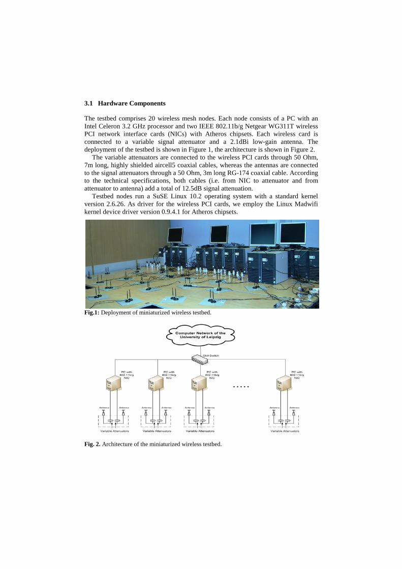
The testbed comprises 20 wireless mesh nodes. Each node consists of a PC with an Intel Celeron 3.2 GHz processor and two IEEE 802.11b/g Netgear WG311T wireless PCI network interface cards (NICs) with Atheros chipsets. Each wireless card is connected to a variable signal attenuator and a 2.1dBi low-gain antenna. The deployment of the testbed is shown in Figure 1, the architecture is shown in Figure 2.
The variable attenuators are connected to the wireless PCI cards through 50 Ohm, 7m long, highly shielded aircell5 coaxial cables, whereas the antennas are connected to the signal attenuators through a 50 Ohm, 3m long RG-174 coaxial cable. According to the technical specifications, both cables (i.e. from NIC to attenuator and from attenuator to antenna) add a total of 12.5dB signal attenuation.
Testbed nodes run a SuSE Linux 10.2 operating system with a standard kernel version 2.6.26. As driver for the wireless PCI cards, we employ the Linux Madwifi kernel device driver version 0.9.4.1 for Atheros chipsets.
Fig.1: Deployment of miniaturized wireless testbed.
Fig. 2. Architecture of the miniaturized wireless testbed.
Each wireless node further possesses a Gigabit ethernet NIC, which is connected to the subnet of the University of Leipzig through a Gigabit switch. This allows a remote management of the wireless nodes from any wired host in the subnet. Hence, wireless experiments can be managed from a remote computer and traces can be copied and evaluated through the wired network. Table 1 shows a detailed description of hardware and software components of the miniaturized testbed.
Multi-hop topologies can be emulated by adjusting the positions of the antenna-stations according to the desired topology. An antenna-station is a joint magnetic board, on which every two antennas of each mesh node are mounted. Such antenna-stations define the logical structure of a mesh node. Since ScaleMesh is deployed in an indoor environment, the shadowing and fading characteristics of wireless signals correspond to the indoor propagation model, which takes into account reflections on walls and floors. For all-wireless office mesh networks as introduced in [8], these indoor shadowing characteristics are identical.
To scale down a distance 𝑑𝑑𝑛𝑛𝑛𝑛𝑛𝑛 −𝑠𝑠𝑠𝑠𝑠𝑠𝑠𝑠𝑠𝑠𝑑𝑑 to a distance 𝑑𝑑𝑠𝑠𝑠𝑠𝑠𝑠𝑠𝑠𝑠𝑠𝑑𝑑 assuming a path loss exponent 𝑝𝑝 the required attenuation can be calculated as follows:
Ω𝑠𝑠𝑠𝑠𝑠𝑠 = − log � 𝑑𝑑𝑠𝑠𝑠𝑠𝑠𝑠𝑠𝑠𝑠𝑠𝑑𝑑
𝑑𝑑𝑛𝑛𝑛𝑛𝑛𝑛 −𝑠𝑠𝑠𝑠𝑠𝑠𝑠𝑠𝑠𝑠𝑑𝑑�10𝑝𝑝 (3.1)
A detailed derivation and validation of this formula can be found in [7].
For mesh networks operating in free space, different shadowing characteristics apply. These different characteristics may as well be considered using outdoor instead of indoor propagation models for downscaling mesh networks. While the signal-to-noise ratio in the testbed may not deliver one-to-one identical results as in a free space mesh network, the acquired results are representative due to the identical characteristics of the IEEE 802.11 wireless link (opposed to simulations). Furthermore, while a large-scale free space multi-hop network has a fixed topology, nodes in our testbed are variably adjustable, making it more convenient for evaluating network protocols.
Table 1. Hardware and software componentents of the miniaturized wireless testbed.
HARDWARE Component Description
PC Siemens ESPRIMO P2510 Celeron 3.2 GHz, 512 Mbytes RAM, 80 Gbytes HDD
Wireless NIC Netgear IEEE 802.11b/g wireless PCI card WG311T with Atheros chipset Variable attenuator Broadwave 751-002-030 variable attenuator, attenuation range 0-30dB in
1 dB steps Coaxial cable 7m aircell5 + 3m RG-174, 50 Ohm with SMA / RPSMA connectors
Antenna Maldol mini 2.1dBi antenna with magnetic mount and 3m SMA cable SOFTWARE
Component Description Operating System SuSE Linux 10.2 with standard kernel version 2.6.26
Wireless NIC driver Madwifi Linux kernel device driver for Atheros chipsets version 0.9.4.1 Multihop routing
protocol OLSR for Linux version 0.5.5 with ETX support
3.2 Software Components
To allow cross-layer performance studies we developed CrossTrace, a software framework for tracing various parameters at MAC-, routing and transport layer. CrossTrace possesses a multi-layer interface and allows tracing of parameters such as MAC retransmission count, per packet receive signal strength and number of bit errors in received frames. These parameters are essential for the understanding of the interaction of layers in IEEE 802.11 based wireless networks. However these parameters cannot be traced using standard network measurement tools such as ping and iperf.
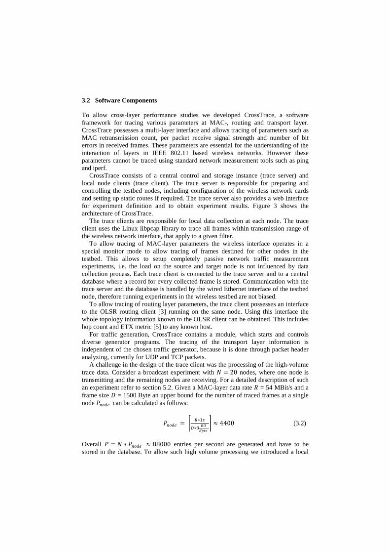
CrossTrace consists of a central control and storage instance (trace server) and local node clients (trace client). The trace server is responsible for preparing and controlling the testbed nodes, including configuration of the wireless network cards and setting up static routes if required. The trace server also provides a web interface for experiment definition and to obtain experiment results. Figure 3 shows the architecture of CrossTrace.
The trace clients are responsible for local data collection at each node. The trace client uses the Linux libpcap library to trace all frames within transmission range of the wireless network interface, that apply to a given filter.
To allow tracing of MAC-layer parameters the wireless interface operates in a special monitor mode to allow tracing of frames destined for other nodes in the testbed. This allows to setup completely passive network traffic measurement experiments, i.e. the load on the source and target node is not influenced by data collection process. Each trace client is connected to the trace server and to a central database where a record for every collected frame is stored. Communication with the trace server and the database is handled by the wired Ethernet interface of the testbed node, therefore running experiments in the wireless testbed are not biased.
To allow tracing of routing layer parameters, the trace client possesses an interface to the OLSR routing client [3] running on the same node. Using this interface the whole topology information known to the OLSR client can be obtained. This includes hop count and ETX metric [5] to any known host.
For traffic generation, CrossTrace contains a module, which starts and controls diverse generator programs. The tracing of the transport layer information is independent of the chosen traffic generator, because it is done through packet header analyzing, currently for UDP and TCP packets.
A challenge in the design of the trace client was the processing of the high-volume trace data. Consider a broadcast experiment with 𝑁𝑁 = 20 nodes, where one node is transmitting and the remaining nodes are receiving. For a detailed description of such an experiment refer to section 5.2. Given a MAC-layer data rate 𝑅𝑅 = 54 MBit/s and a frame size 𝐷𝐷 = 1500 Byte an upper bound for the number of traced frames at a single node 𝑃𝑃𝑛𝑛𝑛𝑛𝑑𝑑𝑠𝑠 can be calculated as follows:
𝑃𝑃𝑛𝑛𝑛𝑛𝑑𝑑𝑠𝑠 = � 𝑅𝑅∗1𝑠𝑠
𝐷𝐷∗8 𝐵𝐵𝐵𝐵𝐵𝐵𝐵𝐵𝐵𝐵𝐵𝐵𝑠𝑠
� ≈ 4400 (3.2)
Overall 𝑃𝑃 = 𝑁𝑁 ∗ 𝑃𝑃𝑛𝑛𝑛𝑛𝑑𝑑𝑠𝑠 ≈ 88000 entries per second are generated and have to be stored in the database. To allow such high volume processing we introduced a local
queue at each testbed node where each record is temporally stored. When the queue length reaches a certain threshold (e.g. 1000 records) we transmit the whole records as a batch to the database.
A further goal in the design of CrossTrace was to ensure repeatability of experiments. Therefore meta data is stored for each experiment, alleviating the reconstruction of the experiment environment. Metadata includes among others time of day, used nodes, used attenuation and the average signal strength between nodes at the beginning of the experiment.
Fig. 3. Software architecture of CrossTrace.
4 Performance Study
Using CrossTrace we conduct a comprehensive performance study, in which we analyze the behavior of the 802.11 MAC-layer with respect to signal strength, frame delivery probability and bit error rate. We derive the transmission probability and MAC-layer bit error rate dependent on signal strength and MAC-layer datarate with and without interfering background traffic. If not stated otherwise experiments are performed with a MAC-layer datarate for unicast and broadcast transmissions set to 11 Mbit/s and rate adaption turned off. This eliminates undesired effects that may be caused by the rate adaptation algorithm, which can influence the results when evaluating and comparing certain performance aspects. Moreover, prior work such as [13] showed that the rate adaptation functionality of 802.11 can influence the throughput of other hosts that share the same radio channel. That is, a host with a lower bit rate can pull down bit rates of other hosts in the vicinity, degrading their performance. RTS/CTS mechanism is disabled for all experiments. The default payload size for TCP/UDP packets is set to 1000 bytes, unless otherwise stated.
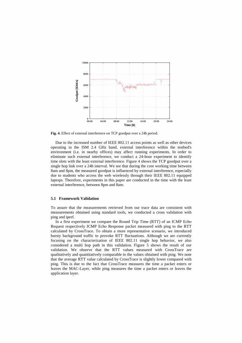
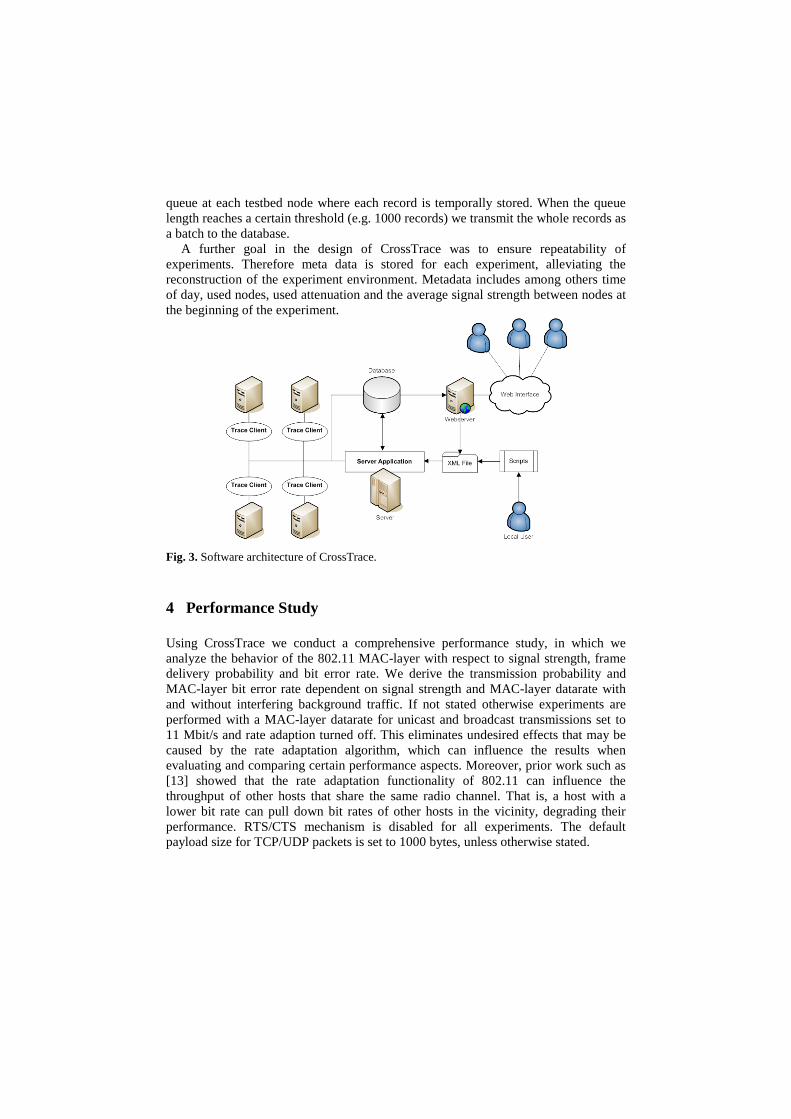
Fig. 4. Effect of external interference on TCP goodput over a 24h period.
Due to the increased number of IEEE 802.11 access points as well as other devices operating in the ISM 2.4 GHz band, external interference within the testbed's environment (i.e. in nearby offices) may affect running experiments. In order to eliminate such external interference, we conduct a 24-hour experiment to identify time slots with the least external interference. Figure 4 shows the TCP goodput over a single hop link over a 24h interval. We see that during the core working time between 8am and 8pm, the measured goodput is influenced by external interference, especially due to students who access the web wirelessly through their IEEE 802.11 equipped laptops. Therefore, experiments in this paper are conducted in the time with the least external interference, between 8pm and 8am.
5.1 Framework Validation
To assure that the measurements retrieved from our trace data are consistent with measurements obtained using standard tools, we conducted a cross validation with ping and iperf.
In a first experiment we compare the Round Trip Time (RTT) of an ICMP Echo Request respectively ICMP Echo Response packet measured with ping to the RTT calculated by CrossTrace. To obtain a more representative scenario, we introduced bursty background traffic to provoke RTT fluctuations. Although we are currently focusing on the characterization of IEEE 802.11 single hop behavior, we also considered a multi hop path in this validation. Figure 5 shows the result of our validation. We observe that the RTT values measured with CrossTrace are qualitatively and quantitatively comparable to the values obtained with ping. We note that the average RTT value calculated by CrossTrace is slightly lower compared with ping. This is due to the fact that CrossTrace measures the time a packet enters or leaves the MAC-Layer, while ping measures the time a packet enters or leaves the application layer.

In a second experiment we compare the throughput measured with iperf to the throughput calculated by CrossTrace. Therefore we use iperf to establish a TCP connection. Again, this validation is conducted for both a single hop and a multi hop path. Figure 6 shows the result of our validation. We observe that there is a slightly higher fluctuation of throughput values when using iperf than CrossTrace. This is due to the fact that iperf measures the number of bytes arriving at application layer. This process shows more burstiness than the arrival of frames at MAC-layer, because of the involved buffering and processing of frame data by the operating system.
Fig. 5. Round Trip Time (RTT) measured at MAC-layer with our framework and at application layer with the standard tool ping for a one-hop (top) and four-hop (bottom) path in the wireless testbed.
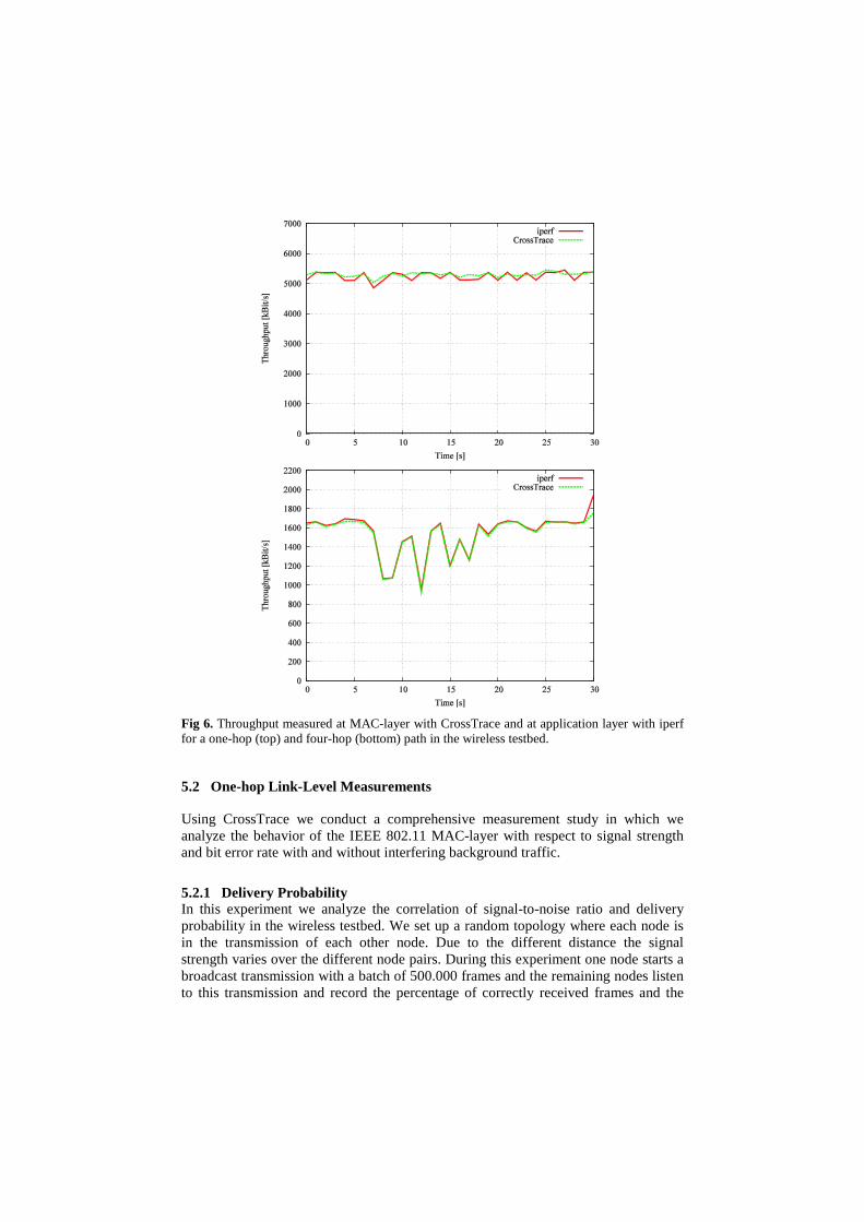
Fig 6. Throughput measured at MAC-layer with CrossTrace and at application layer with iperf for a one-hop (top) and four-hop (bottom) path in the wireless testbed.
5.2 One-hop Link-Level Measurements
Using CrossTrace we conduct a comprehensive measurement study in which we analyze the behavior of the IEEE 802.11 MAC-layer with respect to signal strength and bit error rate with and without interfering background traffic.
5.2.1 Delivery Probability In this experiment we analyze the correlation of signal-to-noise ratio and delivery probability in the wireless testbed. We set up a random topology where each node is in the transmission of each other node. Due to the different distance the signal strength varies over the different node pairs. During this experiment one node starts a broadcast transmission with a batch of 500.000 frames and the remaining nodes listen to this transmission and record the percentage of correctly received frames and the

average signal-to-noise ratio. The experiment is repeated 20 times. In each round a different one of the 20 testbed nodes is chosen as transmitting node. The use of broadcast transmission is required to prevent automatic retransmission, which is used for unicast transmissions by the IEEE 802.11 standard. The experiment is conducted using 11 Mbit/s and 54 Mbit/s MAC-layer datarate.
Figure 7 shows the delivery probability dependent on the signal-to-noise ratio. We observe that at a MAC-layer datarate of 11Mbit/s all links with signal-to-noise ratio of 10dbm or greater have a delivery probability of at least 90%. We note that at a MAC-layer datarate of 54 Mbit/s the situation changes drastically. At a signal-to-ratio of 16dbm there is no successful frame transmission at all. Only links with a signal-to-noise ratio of 23dbm or greater have a delivery probability of at least 90%.
.
Fig. 7. Signal-to-Noise Ratio versus delivery probability for an 11 Mbit/s (top) and 54 Mbit/s (bottom) link in the wireless testbed.

Fig 8. Signal-to-noise ratio versus delivery probability with 2 Mbit/s (top) and 6 Mbits/s (bottom) interfering background traffic in the wireless testbed.
5.2.2 Delivery Probality in the Presence of Interference In this experiment we use CrossTrace to analyze the correlation of signal-to-noise ratio and delivery probability in presence of interfering background traffic. We vary the aforementioned broadcast experiment and introduce an interfering node. We use the variable attenuators to attenuate the output signal of the interfering node, such that interfering and transmitting node are out of carrier sensing range but within interference range. Hence both nodes cannot synchronize their transmissions resulting in frame collisions at the receiving nodes. We repeat this experiment 2 times considering background traffic intensities of 2 Mbit/s and 6 Mbit/s.
Figure 8 shows the delivery probability dependent on the signal-to-noise ratio for 2 different background traffic intensities. We observe that opposed to Figure 7 the scatterplot is much more diffuse. Note that in Figure 7 the delivery probability given a certain signal-to-noise ratio lies within a small interval. For example, all links with a signal-to-noise ratio of 10dbm have a delivery probability between 90% and 100%
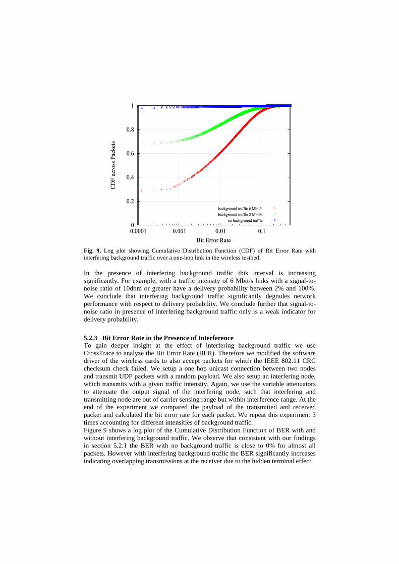
Fig. 9. Log plot showing Cumulative Distribution Function (CDF) of Bit Error Rate with interfering background traffic over a one-hop link in the wireless testbed.
In the presence of interfering background traffic this interval is increasing significantly. For example, with a traffic intensity of 6 Mbit/s links with a signal-to-noise ratio of 10dbm or greater have a delivery probability between 2% and 100%. We conclude that interfering background traffic significantly degrades network performance with respect to delivery probability. We conclude further that signal-to-noise ratio in presence of interfering background traffic only is a weak indicator for delivery probability.
5.2.3 Bit Error Rate in the Presence of Interference To gain deeper insight at the effect of interfering background traffic we use CrossTrace to analyze the Bit Error Rate (BER). Therefore we modified the software driver of the wireless cards to also accept packets for which the IEEE 802.11 CRC checksum check failed. We setup a one hop unicast connection between two nodes and transmit UDP packets with a random payload. We also setup an interfering node, which transmits with a given traffic intensity. Again, we use the variable attenuators to attenuate the output signal of the interfering node, such that interfering and transmitting node are out of carrier sensing range but within interference range. At the end of the experiment we compared the payload of the transmitted and received packet and calculated the bit error rate for each packet. We repeat this experiment 3 times accounting for different intensities of background traffic. Figure 9 shows a log plot of the Cumulative Distribution Function of BER with and without interfering background traffic. We observe that consistent with our findings in section 5.2.1 the BER with no background traffic is close to 0% for almost all packets. However with interfering background traffic the BER significantly increases indicating overlapping transmissions at the receiver due to the hidden terminal effect.

6 Conclusion
We introduced and evaluated CrossTrace, a framework for performing cross-layer measurements in IEEE 802.11 based wireless networks. We conducted a comprehensive measurement study, in which we analyze the behavior of the 802.11 MAC-layer with respect to signal strength and bit error rate. We derive the delivery probability dependent on signal strength and MAC-layer datarate with and without interfering background traffic. We showed that even moderate background traffic can significantly degrade network performance with respect to delivery probability. Such measurements may help to understand the interaction between the different protocol layers and may alleviate the development of new cross-layer designs.
Potential areas of future research include the extension of our measurement study to consider multi-hop paths and dual-radio communication.
7 References
1. Bicket, J., Aguayo, D., Biswas, S., Morris, R.: Architecture and Evaluation of an Unplanned 802.11b Mesh Network. In: Proceedings MobiCom. pp. 31–42. ACM, New York, NY, USA (2005).
2. Camp, J., Robinson, J., Steger, C., Knightly, E.: Measurement Driven Deployment of a Two-tier Urban Mesh Access Network. In: Proceedings MobiSys. pp. 96–109. ACM, New York, NY, USA (2006).
3. Clausen, T. and Jacquet, P.: Optimized Link State Routing Protocol. RFC 3626, http://www.ietf.org/rfc/rfc3626.txt (2003).
4. De, P., Raniwala, A., Krishnan, R., Tatavarthi, K., Modi, J., Syed, N.A., Sharma, S., Chiueh, T.c.: Mint-m: an Autonomous Mobile Wireless Experimentation Platform. In: Proceedings MobiSys. pp. 124–137. ACM, New York, NY, USA (2006).
5. De Couto, D.S.J., Aguayo, D., Bicket, J., Morris, R.: A High-throughput Path Metric for Multi-hop Wireless Routing. Wireless Networks 11(4), pp. 419–434 (2005)
6. ElRakabawy, S.M., Klemm, A., Lindemann, C.: TCP with Adaptive Pacing for Multihop Wireless Networks. In: Proceedings MobiHoc. pp. 288–299. ACM, New York, NY, USA (2005).
7. ElRakabawy, S., Frohn, S., Lindemann, C.: ScaleMesh: A Scalable Dual-Radio Wireless Mesh Testbed. In: Proceedings IEEE WiMesh. pp. 1–6 (2008).
8. Eriksson, J., Agarwal, S., Bahl, P., Padhye, J.: Feasibility Study of Mesh Networks for All-wireless Offices. In: Proceedings MobiSys. pp. 69–82. ACM, New York, NY, USA (2006).
9. Karbaschi, G., Fladenmuller, A., Wolfinger, B.E.: Link-quality Measurement Enhancement for Routing in Wireless Mesh Networks. International Symposium on a World of Wireless, Mobile and Multimedia Networks, pp. 1–9 (2008).
10. Krop, T., Bredel, M., Hollick, M., Steinmetz, R.: Jist/mobnet: Combined Simulation, Emulation, and Real-world Testbed for Ad Hoc Networks. In: Proceedings WinTECH. pp. 27–34. ACM, New York, NY, USA (2007).
11. Lundgren, H., Ramachandran, K., Belding-Royer, E., Almeroth, K., Benny, M.: Experiences from the Design, Deployment, and Usage of the UCSB MeshNet testbed, IEEE Wireless Communications, 13(2), (2006).
12. Martinovic, I., Zdarsky, F.A., Bachorek, A., Jung C., Schmitt, J.B.: Phishing in the Wireless: Implementation and Analysis. In: SEC. pp. 145–156 (2007).
13. Munaretto, A., Fonseca, M., Agha, K., Pujolle, G.: Fair Time Sharing Protocol: A Solution for IEEE 802.11 b Hot Spots. LNCS, vol. 3124, pp. 1261–1266. Springer, Heidelberg (2004).
14. Ott, M., Seskar, I., Siraccusa, R., Singh, M.: ORBIT Testbed Software Architecture: Supporting Experiments as a Service. Proceedings TridentCom, pp. 136-145 (2005).
15. Su, Y., Gross, T.: Validation of a Miniaturized Wireless Network Testbed. In: Proceedings WiNTECH. pp. 25–32. ACM, New York, NY, USA (2008).
16. The network simulator - ns-2. http://www.isi.edu/nsnam/ns/. 17. The Qualnet Simulator, http://www.scalable-networks.com/. 18. Zapotoczky, J.,Wolter, K.: Increasing Performance of the 802.11e Protocol Through
Access Category Shifting. In: Proc. MMB. pp. 61–76 (2008). 19. Zimmermann, A., Wenig, M., Meis, U.: Construction and Evaluation of a Wireless
Mesh Network Testbed. In: Misra, S., Misra, S.C., Woungang, I. (eds.) Guide to Wireless Mesh Networks, pp. 497–519. Springer, London, UK (2009).


