Living at the Crossroads: A Faithful, Relevant Witness Living at the Crossroads Chapter 8.

Crossroads at Westfields
Building II
Chantilly, Va
STEPHEN LUMPP
Structural option
Faculty Consultant: Dr. Andres Lepage
Technical Report 2

Stephen Lumpp Technical Report 2 Page 2 of 52
EXECUTIVE SUMMARY
This report is a study of alternate floor systems for Crossroads at Westfields Building II.
Including the existing floor system, composite metal deck with steel framing, three other
systems were designed, analyzed, and compared to see whether they were viable for further
investigation. The comparison consisted of many factors including architecture, effects on
the lateral system, constructability, cost, fire rating, and impact on the foundation. The main
architectural feature of the building is its open floor plan which is achieved by spans of over
forty feet. Due to the large loads of this office building and long spans the following systems
were chosen to be analyzed:
1. Composite metal Deck with steel framing (existing)
2. Two-way Flat Slab with Drop Panels
3. Hollow Core planks with steel framing
4. Two-way Post-tensioned slab
Based on the preliminary design and analysis of the 4 systems, the existing composite floor
system proved to be the best design for this building, verifying the actual design. The two-
way post-tensioned slab and hollow core offered the best alternatives due to the fact that
they kept the bay sizes unchanged handling the large loads and long spans. The PT system
achieves the least deep floor which allows for the greatest floor to ceiling heights. The Hollow
Core system is very similar to the existing composite system but has the most depth of any
of the floor systems. The two-way flat slab system required adding columns to split the long
spans eliminating it from further consideration. Overall, the hollow core system and post-
tensioned system would provide the best alternatives and other criteria such as vibration,
deflection and lateral effects will be investigated in future reports.

Stephen Lumpp Technical Report 2 Page 3 of 52
TABLE OF CONTENTS
EXECUTIVE SUMMARY……………………………………………………………………… PAGE 2
TABLE OF CONTENTS………………………………………………………………………. PAGE 3
INTRODUCTION……………………………………………………………………………….. PAGE 4
STRUCTURAL SYSTEMS
FOUNDATION SYSTEMS………………………………………………………….. PAGE 5
FLOOR SYSTEMS……………………………………………………………………. PAGE 6
ROOF SYSTEM……………………………………………………………………….. PAGE 7
LATERAL SYSTEM…………………………………………………………………… PAGE 8
COLUMN SYSTEM…………………………………………………………………… PAGE 9
APPLICABLE CODES…………………………………………………………………………. PAGE 10
MATERIALS PROPERTIES………………………………………………………………….. PAGE 11
ALTERNATIVE FLOOR SYSTEMS
COMPOSITE METAL DECK (EXISTING)………………………………………. PAGE 12
2-WAY FLAT SLAB W/ DROP PANELS……………………………………….. PAGE 14
HOLLOW CORE PLANKS…………………………………………………………. PAGE 16
POST-TENSIONED SLAB …………………………………………………………. PAGE 18
COMPARISON TABLE……………………………………………………………………….. PAGE 20
COMPARISONS AND CONCLUSIONS ………………………………………………… PAGE 21
APPENDIX……………………………………………………………………………………….. PAGE 22
Stephen Lumpp Technical Report 2 Page 4 of 52
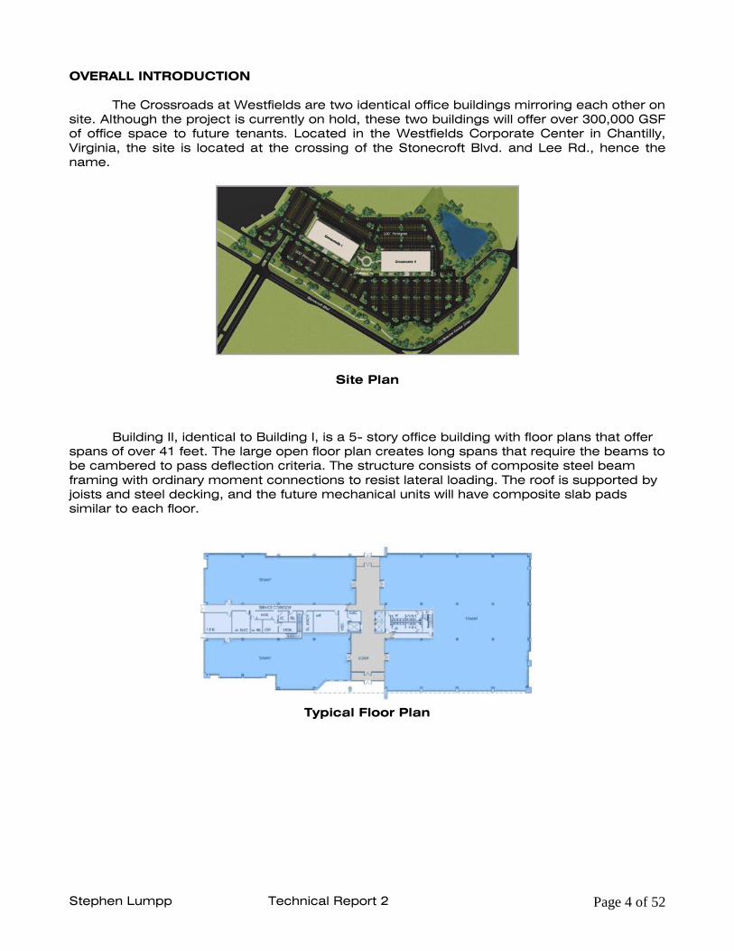
OVERALL INTRODUCTION
The Crossroads at Westfields are two identical office buildings mirroring each other on
site. Although the project is currently on hold, these two buildings will offer over 300,000 GSF
of office space to future tenants. Located in the Westfields Corporate Center in Chantilly,
Virginia, the site is located at the crossing of the Stonecroft Blvd. and Lee Rd., hence the
name.
Site Plan
Building II, identical to Building I, is a 5- story office building with floor plans that offer
spans of over 41 feet. The large open floor plan creates long spans that require the beams to
be cambered to pass deflection criteria. The structure consists of composite steel beam
framing with ordinary moment connections to resist lateral loading. The roof is supported by
joists and steel decking, and the future mechanical units will have composite slab pads
similar to each floor.
Typical Floor Plan

Stephen Lumpp Technical Report 2 Page 5 of 52
EXISTING STRUCTURAL SYSTEMS
FOUNDATION SYSTEMS
The Foundation system consists of reinforced cast-in-place concrete spread footings.
According to the Geotechnical report recommendations prepared by ECS, Ltd the allowable
soil bearing values vary throughout the site. Foundations bearing on the natural „weathered
rock‟ soil classification will be designed with an allowable soil bearing of 6000 psf while
foundations bearing on engineered fill will be designed for soil bearing of 3000 psf. The
concrete strength shall be 3000 psi.
According to recommendations in the Geotechnical Report, the Slab on Grade will bear on
the natural soil. The slab is a 4” thick cast-in-place concrete with 6x6–10/10 welded wire
mesh (WWM), laid on a 6-mil fiberglass reinforced polyethylene vapor barrier and 4” of
washed gravel. Interior SOG will have a compressive strength of 3000 psi, while exterior SOG
will have a strength of 4500 psi.
Figure 1- Typical Foundation section

Stephen Lumpp Technical Report 2 Page 6 of 52
FLOOR SYSTEMS
A typical floor in the Building II consists of 3” 20 gauge composite steel deck with 3-1/4”
lightweight concrete slab totaling a total slab thickness of 6-1/4”. The slab shall be
reinforced with 6X6-10/10 WWM and have a compressive strength of 3000 psi. The floor is
supported by A992 wide flange beams with studs dimensioned at ¾” in diameter and 5 ¼”
in length. The beams are spaced at 10‟ o/c and span 41‟-8” in a typical exterior bay and 30‟-
0” in a typical interior bay, as you can see in Figure 2 below. Depending on the floor, the
beams will be cambered from an 1” to 1½” and will vary in size and weight. Typical interior
girders are W24-62 spanning 30‟-0”, while typical exterior girders vary in size and also span
30‟-0”.
FIGURE 2 – Typical exterior floor bay

Stephen Lumpp Technical Report 2 Page 7 of 52
ROOF SYSTEM
As seen in Figure 3, the roof system is comprised of 1-1/2” 22 gauge Type B wide rib
galvanized roof deck, on K series bar joists and steel girders. Light-gage framing makes up
the 4‟ parapet and the screen wall encompassing the roof. Precast panels frame into each
floor including the roof.
Rooftop Mechanical pads for future tenant equipment shall be constructed similar to the
typical floor system consisting of 3” 20 gauge composite steel deck with 3-1/4” lightweight
concrete slab totaling a total slab thickness of 6-1/4”. The slab shall be reinforced with 6X6-
10/10 WWM and have a compressive strength of 3000 psi.
FIGURE 3 – Typical exterior roof section

Stephen Lumpp Technical Report 2 Page 8 of 52
LATERAL SYSTEM
The lateral resisting system for wind and seismic loads consists of a number of structural
steel moment frames running in both directions. Lateral loading is transferred from precast
panels (connected at each floor) to each individual floor. Once transferred into the floor
system, the load is transferred into composite beams which make up the framing and then
into the columns. The columns and beams are connected by a moment connection seen in
Figure 4. the columns transfer the rest of the load into the foundation.
FIGURE 4 – Typical Beam to Column Moment connection
Figure 5 clearly shows the four moment frames positioned in each direction, North-South
and East-West, supporting the building laterally. In both directions the moment frames are
positioned symmetrically about the center axis. The North-South lateral system is 2 sets of
parallel moment frames anchoring each end bay. The East-West lateral system is a set of 2
moment frames on each exterior side of the building. The beam sizes vary.
FIGURE 5 – Typical Floor plan with moment frames

Stephen Lumpp Technical Report 2 Page 9 of 52
COLUMN SYSTEM
Having a very uniform design layout the column system consists of typical exterior bays of
30‟-0” x 41‟-8” and interior bays of 30‟-0” x 30‟-0”. All of the columns consist of either a
gravity resisting member or a combined lateral and gravity resisting member. Each columns
is spliced at 4 feet past the third floor, regardless of its resisting system. All columns vary in
size depending on location and load resistance capabilities.
FIGURE 6 – Typical splice connection

Stephen Lumpp Technical Report 2 Page 10 of 52
APPLICABLE CODE
Design Codes used for Original Design:
o International Building Code, 2003 Edition
o Viginina Uniform State Building Code, 2003
o American Society of Civil Engineers (ASCE)
ASCE 7 – 02, Minimum Design Loads for Buildings and Other Structures
o American Institute of Steel Construction (AISC)
Steel Construction Manual, Ninth Edition (LRFD)
o American Concrete Institute (ACI)
Building Code Commentary 318-02
Code Substitutions/ Additional References used for Thesis Design:
o International Building Code, 2006 Edition
o American Society of Civil Engineers (ASCE)
ASCE 7 – 05, Minimum Design Loads for Buildings and Other Structures
o American Institute of Steel Construction (AISC)
Steel Construction Manual, Thirteenth Edition (LRFD)
o American Concrete Institute (ACI)
Building Code Commentary 318-08

Stephen Lumpp Technical Report 2 Page 11 of 52
MATERIALS AND PROPERTIES
Steel:
Wide flange shapes 50 ksi (A992)
Square or Rectangular Tubes 46 ksi (A500 Grade B)
Round Pipes 42 ksi (A500 Grade B)
Miscellaneous Steel 36 ksi (A36)
Bolts 36/45 ksi (A325N/A490N)
Steel Studs 60 ksi (A108)
Weld Strength 70 ksi (E70XX)
Concrete:
Foundations, Int. Wall & Int. SOG f‟c = 3000 psi
Ext. SOG and Pads f‟c = 4000 psi
Deck supported slabs (lightweight) f‟c = 3000 psi
Reinforcement:
Stirrups and Ties 40 ksi (A615)
All other 60 ksi (A615)
Welded Wire Fabric: (A185)
Cold-Formed Steel Framing:
20 Gage 33 ksi (A653)
18 Gage 33 ksi (A653)
16 Gage 50 ksi (A653)
Note: Material strengths are based on American Society for Testing and Materials (ASTM)
Standard ratings.

Stephen Lumpp Technical Report 2 Page 12 of 52
ALTERNATIVE FLOOR SYSTEMS
Composite Metal Deck (Existing System)
The composite metal deck system is viable floor system for the Crossroads at Westfields
considering it is the existing floor system of the building. One of the main architectural
features of the building is the 41‟-8” spans that are in the typical exterior bays, allowing for
maximum office space, as seen in figure 8. The composite system is a very effective system
for this because of its ability to span long lengths and resist heavy loads, while meeting
deflection criteria. The fire code for Building II requires a 1-hour rating for floor systems
structural members. The 6 ¼” slab satisfies the 1-hour rating and the steel framing
members require fireproofing to meet the criteria. Although larger wide flanges are needed
to meet the deflection criteria, the overall weight of the floor system is approximately 66 PSF
which is relatively light compared to the other floor systems proposed.
The Construction process of the composite system is very efficient and is one of the main
reasons for this is the existing system for Building II. The erection of the steel members is
much quicker than having a concrete structure where formwork and shoring is required. The
slab can be poured at a much faster rate because the slab does not require many breaks.
The cost of the floor system is $27.85 per SF according to RS Means and is very similar in
price range to the other alternate floor systems. The one negative to this system is the depth
of the floor system which is over 30” deep (24” steel sections and 6 ¼” slab) reducing floor
to ceiling heights.
Advantages
- Long spans and capable of resisting large loads
- Meets architectural and structural criteria
- Relatively light weight system allowing for smaller foundations
- Efficient construction process
- Relatively cost effective
Disadvantages
- Larger steel members reducing the floor to ceiling height
The number of advantages clearly outweighs the disadvantages showing why this system is
not only viable but was chosen as the existing floor system for the Crossroads at Westfields
Building II.
FIGURE 7 – COMPOSITE FLOOR SECTION

Stephen Lumpp Technical Report 2 Page 13 of 52
FIGURE 8 – TYPICAL COMPOSITE LAYOUT

Stephen Lumpp Technical Report 2 Page 14 of 52
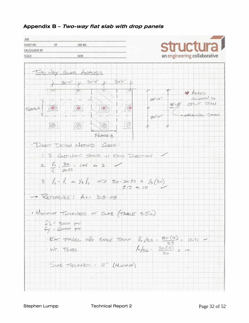
2-way Flat Slab with Drop Panels
The initial goal as stated in the executive summary was to maintain the original column grid
which is the main architectural feature of the floor plan allowing for an open office floor. To
keep the original span of 41‟-8” in the exterior bays the slab thickness would have needed to
be a minimum of 16” thick which would not have been very economical. Therefore,
additional columns were added in the middle of the long spans cutting the span length to
20‟-10” and creating two 30‟x21‟ bays in lieu of one 42‟x30‟ bay. Unfortunately, this takes
away from the “open” floor plan but is more economical resulting in an 11” thick slab instead
of a 16” thick slab. The columns chosen were 24” circular with capital and drop panel. The
drop panel is used to reduce the slab thickness and remove punching shear. The reason for
the circular columns in lieu of rectangular is strictly for architectural aesthetic and would be
analyzed for further feasibility if this system was considered a viable solution.
This system requires a totally different lateral system than the existing moment frame. Shear
walls would most likely be used on the exterior faces of the building and in the main core
around the elevator and stair shafts. Although the slab thickness is only 11” and the drop
panels add an additional 4” the floor depth will increase with the addition of other building
systems such as mechanical ducts. The weight of the floor system is approximately 137 PSF
which is somewhat heavy and coupled with the added shear walls and columns the
foundation would need to be redesigned. Although the construction time for this system is
especially long due to shoring and formwork, the cost of the system is relatively cheap
according to RS Means totaling only $21.05.
Advantages
- Cost is relatively cheap
- Fireproofing easily meets criteria
- Floor depth is only 15+ inches allowing for greater ceiling heights
Disadvantages
- Architectural floor plan is altered resulting in less “open space”
- Weight of floor system is high
- Construction time is very long due to formwork and shoring
Overall, I would not consider this system viable as an alternate solution mostly because it
requires a change to the architectural floor plan. Getting rid of the long spans defeats the
purpose to have an “open” floor plan for office use.
FIGURE 9 – VIEW OF FLAT SLAB WITH DROP PANELS

Stephen Lumpp Technical Report 2 Page 15 of 52
FIGURE 10 – TYPICAL FLAT SLAB LAYOUT

Stephen Lumpp Technical Report 2 Page 16 of 52
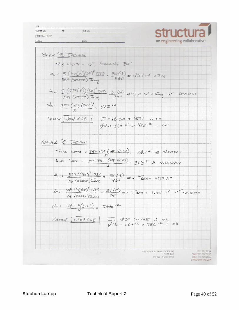
Hollow Core Plank
This system meets the goal to keep the architectural floor plan the unchanged. The column
grid was altered and the steel framing plan was slightly altered by the subtraction of one
beam running in the long direction of the typical bay. The reason why a beam was able to be
removed was because the hollow core plank is able to span further distances than the
composite steel deck. One negative is that beam spanning that long direction is 30” deep
alone, not to mention the additional 6” for the plank itself. That results in a 36” deep floor
system minimizing floor to ceiling heights but also meeting the deflection criteria for the
system. The weight of the building results in 59 PSF which is relatively light in weight and will
not effect the existing foundation.
This system, similar to the existing system, easily meets the 1-hour fire rating for the slab
and requires fireproofing for the steel members. The constructability of the system is very
efficient and fast, including the erection of the steel and installation of the precast planks.
One negative is that the lead time for this system is slower because of the ordering and
shipping of the system. The Cost of the planks is $10.59 while the cost of the steel framing is
approximately $17 totaling $27.59 which is very comparable to the existing system.
Advantages
- Architectural plan remained unchanged
- Weight of the building is lighter
- Construction time is very fast and efficient
Disadvantages
- Floor depth is 36” minimizing ceiling to floor heights
- Lead time is long due to ordering and shipping
After analyzing this floor system, many similarities were noticed to the existing floor plan with
the exception that the lead time is much longer. The other disadvantage is the floor depth is
greater than that of the existing system. Overall, the similarities to the existing make this a
possibility as an alternative for the Crossroads and Westfields Building II.
FIGURE 11 – HOLLOW CORE SLAB SECTION

Stephen Lumpp Technical Report 2 Page 17 of 52
FIGURE 12 – TYPICAL HOLLOW CORE LAYOUT

Stephen Lumpp Technical Report 2 Page 18 of 52
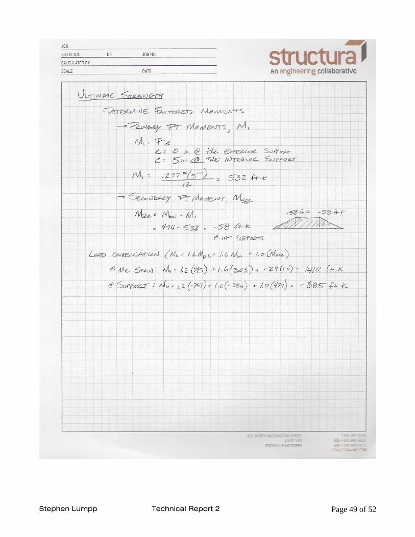
2-way Post-Tensioned Slab
One of the many advantages of a post-tensioned slab is its ability to achieve long spans
economically, and that was the goal for this floor system: minimize the thickness of the slab
and keep the long spans. The minimum slab thickness is 12” but unfortunately, due to
punching shear a 1” deep, 43” x 43” drop panel was required. Since the main architectural
feature of the building is to keep “open” floor plans, this system is probably worth looking
into further. The 12” slab easily meets the 1-hour fire rating and the weight of the floor
system is 150 PSF which is relatively heavy compared to the composite system with the
same number of columns. A new lateral system would have to be designed which may also
add weight to the structure.
Post-Tensioned slab are good in deflection and vibration control as well as crack control. The
cost is similar to the other systems totaling $32 per SF with additional costs possible. These
additional costs come with construction process. The laying of the tendons and placing of
formwork require addition time. Due to the high jacking forces during installation specialized
supervision and safety precautions are highly recommended.
Advantages
- Reduced structural depth and longer spans
- Can carry much higher loading
- Great in deflection, vibration and crack control
Disadvantages
- A little expensive due to many safety precautions during installation
- Construction takes a longer for several reasons
Overall, this system is viable solution for an alternate floor system of the Crossroads at
Westfileds Building II because it can achieve long spans while maintaining a relatively thin
floor depth.
FIGURE 13 – PT TENDON LAYOUT

Stephen Lumpp Technical Report 2 Page 19 of 52
FIGURE 14 – TYPICAL POST-TENSION SLAB LAYOUT

Stephen Lumpp Technical Report 2 Page 20 of 52
Table 1
Floor Systems - Comparisons
Item Composite Slab
(Existing) 2-Way Flat Slab w/
Drop Panels Hollow Core Plank w/ Steel Framing
Post-Tensioned
Slab
Architectural Requirements
(Bay Dimensions unchanged)
Yes No Yes Yes
Lateral System No changes Shear Walls - Both
Directions No changes
Shear Walls - Both Directions
Fire Ratings
Slab - 1-hour Rating
Framing - fireproofing
Slab - 1-hour Rating Slab - 1-hour Rating
Framing - fireproofing Slab - 1-hour
Rating
Slab Depth (in.) 6.25" 11" (+ 4" Drop Panels) 6" 12" ( + 1" Drop
Panels)
Depth of floor sytem (in)
30" (6.25" slab + 24" steel members)
15"+ (11" slab + 4" drop panels + possible
ductwork)
36" (6" slab + 30" steel members)
13"+ (12" slab + 1" drop panel
+ possible ductwork)
Weight (PSF) 66 PSF 137 PSF 59 PSF 150 PSF
Foundation Impact
None Re-design necessary Very Little Re-design necessary
Construction - Process
Efficient Inefficient
(more time and labor) Efficient, but requires
longer lead time
Inefficient (more time, labor and additional
supervision)
Material Cost (SF)
21 11.1 21 (8.5+12.5) 19.4
Installation Cost (SF)
6.85 9.95 6.59 (2.09 +4.5) 11.4 (+1.2 for
equip.)
Overall Cost (Per SF)
27.85 21.05 27.59 32
Deflection Meets Criteria Further investigation Meets Criteria Further
investigation
Vibration Further
investigation Further investigation Further investigation
Further investigation
Viable System for Future
consideration Yes No Yes Yes

Stephen Lumpp Technical Report 2 Page 21 of 52
COMPARISONS AND CONCLUSION
The goal of this report was investigate viable alternatives for the floor system of the
Crossroads at Westfields Building II. Including the existing floor system, a composite design,
three schematic designs of additional systems were conducted to test the feasibility of each.
Each system was compared to the others through a variety of criteria which can be found in
Table 1 located on page 20 in the report. After weighing all of the comparisons it was
concluded that the two-way post-tension slab and hollow core floor systems were the best
alternatives to the existing system, although the existing composite slab proved to be the
best choice for the design. The two-way flat slab will no longer be considered in future
reports because it required the addition of extra columns splitting the exterior bays in half.
The three viable choices can all span long lengths and resist heavier loads. The hollow core
and the existing composite floor systems are very similar when compared, both are very
easy to construct, both require additional fire proofing of their steel members, both are
relatively the same cost per square foot, and both have little impact on the foundation and
lateral system in place now. The one negative of the two systems is that they both require
very deep floors overall, reducing the floor to ceiling height. The PT system on the other
hand, maximizes the floor to ceiling height having the least deep floor system. It requires no
additional fire proofing and is probably meets vibration criteria easily because its only
concrete (further investigation will be conducted on vibration). Some flaws to the PT system
are cost and constructability. It costs more than the other two systems per square foot and
takes much longer to construct.
After this preliminary design it is concluded that three systems, composite, post-tension, and
hollow core will be further investigated. Other criteria will be considered such as deflection,
vibration and the effects the lateral system will have on the building and foundation.

Stephen Lumpp Technical Report 2 Page 22 of 52
APPENDIX

Stephen Lumpp Technical Report 2 Page 23 of 52
Appendix A – Composite Metal Deck on steel framing

Stephen Lumpp Technical Report 2 Page 24 of 52

Stephen Lumpp Technical Report 2 Page 25 of 52

Stephen Lumpp Technical Report 2 Page 26 of 52

Stephen Lumpp Technical Report 2 Page 27 of 52

Stephen Lumpp Technical Report 2 Page 28 of 52

Stephen Lumpp Technical Report 2 Page 29 of 52

Stephen Lumpp Technical Report 2 Page 30 of 52

Stephen Lumpp Technical Report 2 Page 31 of 52
Stephen Lumpp Technical Report 2 Page 32 of 52
Appendix B – Two-way flat slab with drop panels

Stephen Lumpp Technical Report 2 Page 33 of 52

Stephen Lumpp Technical Report 2 Page 34 of 52

Stephen Lumpp Technical Report 2 Page 35 of 52

Stephen Lumpp Technical Report 2 Page 36 of 52

Stephen Lumpp Technical Report 2 Page 37 of 52

Stephen Lumpp Technical Report 2 Page 38 of 52
Appendix C – Hollow Core Plank with Steel Framing

Stephen Lumpp Technical Report 2 Page 39 of 52
Stephen Lumpp Technical Report 2 Page 40 of 52

Stephen Lumpp Technical Report 2 Page 41 of 52

Stephen Lumpp Technical Report 2 Page 42 of 52
Appendix D – Two-way post-tension slab

Stephen Lumpp Technical Report 2 Page 43 of 52

Stephen Lumpp Technical Report 2 Page 44 of 52

Stephen Lumpp Technical Report 2 Page 45 of 52

Stephen Lumpp Technical Report 2 Page 46 of 52

Stephen Lumpp Technical Report 2 Page 47 of 52

Stephen Lumpp Technical Report 2 Page 48 of 52
Stephen Lumpp Technical Report 2 Page 49 of 52

Stephen Lumpp Technical Report 2 Page 50 of 52

Stephen Lumpp Technical Report 2 Page 51 of 52

Stephen Lumpp Technical Report 2 Page 52 of 52