
CROSSOVER PRODUCT™ - The Home Depot · PDF fileendurance™ and titan pro™...
12
CROSSOVER PRODUCT™ STRUCTURAL POST INSTALLATION INSTRUCTIONS • Flush-Mount: pp. 2-5 • Fascia (Thru)-Mount: pp. 6-9 • Core-Mount: pp. 10-11 Compatible with ENDURANCE™ and TITAN PRO™ Railing Systems
Transcript of CROSSOVER PRODUCT™ - The Home Depot · PDF fileendurance™ and titan pro™...

CROSSOVER PRODUCT™STRUCTURAL POST INSTALLATION INSTRUCTIONS
• Flush-Mount: pp. 2-5• Fascia (Thru)-Mount: pp. 6-9• Core-Mount: pp. 10-11
Compatible withENDURANCE™ and TITAN PRO™ Railing Systems

2
FLUSH-MOUNT POST INSTRUCTIONS•Determineplacementofallstructuralpostsbeforebeginning
installation.
•RDIrailingkitsaremanufacturedfora36”or42”finishedrailheightwitha2”standardbottomspace.
COMPONENT LIST: Checkthekittoensureallcomponentsareincluded.
A) Vinyl Shim (2)
B)ExtrusionSetScrew(1)
C)CenteringExtrusion(2)
D)GalvanizedSteelPost(1)
A
B
C
D
Warning: Always wear
safety goggles.
3
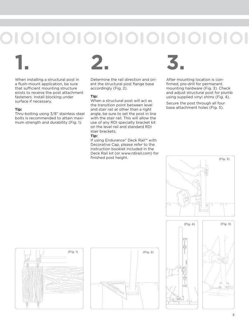
1. 2. 3.Wheninstallingastructuralpostinaflush-mountapplication,besurethatsufficientmountingstructureexiststoreceivethepostattachmentfasteners.Installblockingundersurfaceifnecessary.
Tip: Thru-boltingusing3/8”stainlesssteelboltsisrecommendedtoattainmaxi-mumstrengthanddurability(Fig.1).
Determinetheraildirectionandori-entthestructuralpostflangebaseaccordingly(Fig.2).
Tip: Whenastructuralpostwillactasthetransitionpointbetweenlevelandstairrailatotherthanarightangle,besuretosetthepostinlinewiththestairrail.ThiswillallowtheuseofanyRDIspecialtybracketkitonthelevelrailandstandardRDIstairbrackets.Tip: IfusingEndurance®DeckRail™withDecorativeCap,pleaserefertotheinstructionbookletincludedintheDeckRailkit(orwww.rdirail.com)forfinishedpostheight.
Aftermountinglocationiscon-firmed,pre-drillforpermanentmountinghardware(Fig.3).Checkandadjuststructuralpostforplumbusingsuppliedvinylshims(Fig.4).
Securethepostthroughallfourbaseattachmentholes(Fig.5).
(Fig. 4) (Fig. 5)
(Fig. 1)
(Fig. 3)
(Fig. 2)

4
6.4. 5.Positionthelowerextrusionaligningitwiththeproposedrailingdirection(Fig.6).Ensurethatthepre-mountedtopcenteringextrusionisaligned as well.
Note: RDIrailingkitsaremanufacturedfora36"or42”finished-railheightwitha2"standardbottomspace.Ifotherheightsorbottomspacesaredesired,adjusttheheightofthecenteringextrusionaccordingly.
Note: IfinstallingEndurance® ADA Hand Rail™ontoapost,determinethemountinglocationandcreatesufficientattachmentbyblockingoutpostwith1”materialorbypurchasingathirdcenteringextrusionandinstallingatdesiredlocation(Fig7).
Slidethevinylsleeveoverthecenteringextrusion.Markandcutthe sleeve to length.
Tip: Thesleeveshouldextendabovethedesiredrailheightenoughtoallowclearanceforapostcap(Fig.8).
Note: Ifusingaturnednewelsleeve*,besuretoleaveenoughflatareatoacceptrailattachmentbrackets(Fig.9).Removethetopcenteringextrusionsetscrewandtheextrusion.Usethisscrewtoattachthebottomcenteringextrusiontothepost.Slidethetopextrusionontothepostaftertheturnedsleevehas been installed.
*Endurancerailkitsmeasure34”or40”fromthebottomofthebottomrailtothetopofthetoprail.
Slidethevinylsleeveoverthestruc-turalpostandthecenteringextru-sions(Fig.10).
Note: Thetopcenteringextrusionmayneedtoberepositioneddependingonyourapplication.Forexample,instairrailingapplications,thecenter-ingextrusionmayneedtoberaisedtoallowattachmentofthestairbrackets.
(Fig. 7)
(Fig. 10)(Fig. 8) (Fig. 9)
6.5"Minim
um
(Fig. 6)
34"or40"*

5
7. Thepostisnowreadytoaccepttherailinginstallation(Fig.11).
Note:PostcapsshouldbegluedonAFTERinstallationiscomplete.Simplyapplyasmallamountofvinyladhesivetothecaptopermanentlysecure.
(Fig. 11)

6
•Determineplacementofallstructuralpostsbefore beginning installation.
•RDIrailingkitsaremanufacturedfora36”or42”finished-railheightwitha2”standardbottomspace.
FASCIA (THRU)-MOUNT POST INSTRUCTIONS
COMPONENT LIST: Checkthekittoensureallcomponentsareincluded.
A) Vinyl Shim (2)
B)ExtrusionSetScrew(1)
C)CenteringExtrusion(2)
D)SteelPost(1)
A
B
C
D
Warning: Always wear
safety goggles.

7
(Fig. 5)
1. 2. 3.
(Fig. 1)
Wheninstallingastructuralpostinafascia(thru)-mountapplication,besurethatsufficientmountingstructureexiststoreceivepostattachmentfasteners.
Whenmountingtoastraightface,threefastenersshouldbeused(Fig.1).Inaninsidecornerapplication,fivefastenersshouldbeusedtomaximizestrengthinbothdirections(Fig2).
Note: Thru-boltingusing3/8”stainlesssteelboltsisrecommendedtoattainmaximumstrengthanddurability.
Ensuringthatthepostisplumbfromside-to-sideandattheappropriateheight,clampinplace(Fig.3).
Postsshouldbeinstalledataheightof36”foranRDIresidentialrailingkitand42”foranRDIcommercialrailingkit.
Usingtwostandarddeckscrews,temporarilysecurethepostinplacethroughthetwosmallerholesinthepost(Fig.4).
Tip: IfusingEndurance®DeckRail™withDecorativeCap,pleaserefertotheinstructionbookletincludedintheDeckRailkit(orwww.rdirail.com)forfinishedpostheight.
Aftermountinglocationiscon-firmed,pre-drillforpermanentmountinghardware(Fig.5).Usingtheprovidedvinylshims,plumbthepostandpermanentlysecurewithatleastthreemountingfasteners(Fig.6,7).
(Fig. 3) (Fig. 4) (Fig. 6) (Fig. 7)
vinyl shim
(Fig. 2)

8
6.4. 5.
(Fig. 8)
(Fig. 9) (Fig. 13)
Positionthelowerextrusionaligningitwiththeproposedrailingdirection(Fig.8).Ensurethatthepre-mountedtopcenteringextrusionisaligned as well.
Note: RDIrailingkitsaremanufacturedfora36”or42”finished-railheightwitha2”standardbottomspace.Ifotherheightsorbottomspacesaredesired,adjusttheheightofthecenteringextrusionaccordingly.Note: IfinstallingEndurance® ADA HandRailontopost,determinethemountinglocationandcreatesufficientattachmentbyblockingoutpostwith1”materialorbypurchasingathirdcenteringextrusionandinstallingatdesiredlocation(Fig9).
Slidethevinylsleeveoverthecenteringextrusion.Markandcutthe sleeve to length.
Tip: Thesleeveshouldextendabovethedesiredrailheightenoughtoallowclearanceforapostcap(Fig.10).
Note: Ifusingaturnednewelsleeve*,besuretoleaveenoughflatareatoac-ceptrailattachmentbrackets(Fig.11).Removethetopcenteringextru-sionsetscrewandtheextrusion.Usethisscrewtoattachthebottomcenteringextrusiontothepost.Slidethetopextrusionontothepostaftertheturnedsleevehasbeeninstalled.*Endurancerailkitsmeasure34”or40”fromthebottomofthebottomrailtothetopofthetoprail.
Slidethecutvinylsleeve overthestructuralpostandthecen-teringextrusions(Fig.12).
Note: Thetopcenteringextrusionmayneedtoberepositioneddependingonyourapplication.Forexample,instairrailapplications,thecenteringextrusionmayneedtoberaisedtoallowattachmentofthestairbrack-ets.
Note: Insomecases,thevinylsleevewillneedtobenotchedtoextendbelowtheplaneofthestandingsurfacetohidetheposttailandmountinghardware(Fig.13).*Endurancerailkitsmeasure34”or40”fromthebottomofthebottomrailtothetopofthetoprail.
(Fig. 12)
(Fig. 10) (Fig. 11)
6.5"Minim
um
34"or40"*

9
7.
(Fig. 14)
Thepostisnowreadytoaccepttherailinginstallation(Fig.14).
Note: PostCapsshouldbegluedonAFTERinstallationiscomplete.Simplyapplyasmallamountofvinyladhesivetothecaptopermanentlysecure.

10
CORE-MOUNT POST INSTRUCTIONS
COMPONENT LIST: Checkthekittoensureallcomponentsareincluded
•Determineplacementofallstructuralpostsbeforebeginninginstallation.
•RDIrailingkitsaremanufacturedfora36”or42”finished-railheightwitha2”standardbottomspace.
A) Vinyl Shim (2)
B)ExtrusionSetScrew(1)
C)CenteringExtrusion(2)
D)SteelPost(1)
A
B
C
D
Warning: Always wear
safety goggles.
11
(Fig. 3) (Fig. 4)
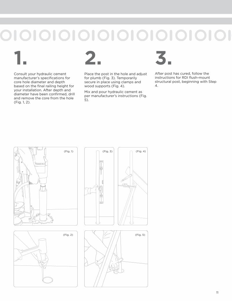
2.1. 3.Consultyourhydrauliccementmanufacturer’sspecificationsforcoreholediameteranddepthbasedonthefinalrailingheightforyourinstallation.Afterdepthanddiameterhavebeenconfirmed,drillandremovethecorefromthehole(Fig.1,2).
Placethepostintheholeandadjustforplumb(Fig.3).Temporarilysecureinplaceusingclampsandwoodsupports(Fig.4).
Mixandpourhydrauliccementaspermanufacturer’sinstructions(Fig.5).
Afterposthascured,followtheinstructionsforRDIflush-mountstructuralpost,beginningwithStep4.
(Fig. 2)
(Fig. 1)
(Fig. 5)

RAILINGDYNAMICS,INC.
FORHOME,FORLIFE.™
135STEELMANVILLEROAD
EGGHARBORTOWNSHIP,NJ08234
TEL:(877)420-7245
FAX:(866)277-5160
E-MAIL:[email protected]
URL:WWW.RDIRAIL.COM
EMISP/4.11


![Xerox WorkCentre 7132 / 7228 / 7235 / 7245 Driver ... · 7132/7228/7235/7245 only Install Guide - 8 - v.2.0 If you clicked [Browse] in the previous step, browse to the folder where](https://static.fdocuments.us/doc/165x107/60a5b4a1d7aaf6150208c772/xerox-workcentre-7132-7228-7235-7245-driver-7132722872357245-only-install.jpg)

