Crosshead Crosshead pin connects piston to the connecting rod. On either side of the crosshead pins...
11
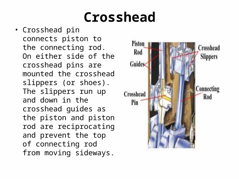
Crosshead • Crosshead pin connects piston to the connecting rod. On either side of the crosshead pins are mounted the crosshead slippers (or shoes). The slippers run up and down in the crosshead guides as the piston and piston rod are reciprocating and prevent the top of connecting rod from moving sideways.
-
Upload
virginia-evans -
Category
Documents
-
view
242 -
download
2
Transcript of Crosshead Crosshead pin connects piston to the connecting rod. On either side of the crosshead pins...
Crosshead• Crosshead pin connects
piston to the connecting rod. On either side of the crosshead pins are mounted the crosshead slippers (or shoes). The slippers run up and down in the crosshead guides as the piston and piston rod are reciprocating and prevent the top of connecting rod from moving sideways.

• The crosshead pin sits in the crosshead bearing. The crosshead bearings are of two types. It may be of the forked type, where the bearing housings are mounted on top of the connecting rod on either side of the piston rod. The piston rod passes through a hole in the crosshead pin and secured by a nut.

• Or, it may be of the continuous type, where the bearing housing is formed by the top of connecting rod. Modern engines are fitted with a continuous type of crosshead bearing.

• The top of the connecting rod swings about the crosshead pin and changes direction each time the piston reaches mid stroke. The relative sliding speed between the pin and bearing at mid stroke is zero; accelerates to maximum as the piston reaches top or bottom centres and then decelerates back to zero as the piston approaches mid stroke and connecting rod changes direction.

• This means that hydrodynamic lubrication, when bearing is separated from pin by a film of lube oil occurs over a part of the swing when the relative sliding speed of the two components is high. Hence, this bearing is difficult to lubricate effectively by conventional method.

• This means that hydrodynamic lubrication, when bearing is separated from pin by a film of lube oil occurs over a part of the swing when the relative sliding speed of the two components is high.

• The load on the crosshead pin is always downwards, so it is the bottom half of the bearing, which is subjected to wear. Because of high loads, the bearing material is tin aluminium alloy bonded to a steel shell. The crosshead pin is highly polished to a mirror finish. To accommodate higher downward load and aid in effective lubrication, the crosshead pin has a large diameter.

• This increases the relative sliding speed between crosshead pin and the bearing, as well as reduces the load on per unit area of the bearing. The bottom half of the crosshead bearing shells have oil gutters cut in them to assist the distribution of oil (this the only bearing to have such oil gutters cut parallel to the pin).

Lubricating oil is supplied to the crosshead by a swinging arm or a telescopic pipe and sometimes is boosted in pressure to assist in forming an oil film for hydrodynamic lubrication. The crosshead slippers are mounted on stepped journals machined on either side of the crosshead pin. They are secured in place by end plates. The slippers float in the journal to allow for any misalignment in the guides. The rubbing faces are lined with white metal. Lube oil is supplied to the slipper rubbing faces from the crosshead oil supply. The slippers have gutters machined in them to assist in spreading of lube oil.

• The guide faces are either machined into the A-frames or are cast separately and bolted to the A-frame. The alignment of the guides is very important as is the clearance between the slippers and the guide.

• If the alignment is out of true or there is excessive clearance, than there will be excessive wear between piston rod and stuffing box and between piston and cylinder liner.