Cross Sled A split fence · A split fence guarantees accurate cuts. Cross IMPROVEDcut Sled by Tom...
5
Transcript of Cross Sled A split fence · A split fence guarantees accurate cuts. Cross IMPROVEDcut Sled by Tom...


2 AmericanWoodworker.com2 AmericanWoodworker.com
A split fence guarantees accurate cuts.
IMPROVED Crosscut
Sledby Tom Caspar
Whenever I want to make an accurate square cut, I reach for my crosscut sled. Unlike
a miter gauge, its right-angle setting doesn’t need constant tweaking. My cuts are always right on the money.
Crosscut sleds have been around for a long time, but few are ideal. Many are heavy and hard to store. Most develop an extra-wide saw cut in the fence and allow the blade to throw sawdust in your face. My design solves all these problems.

AmericanWoodworker.com 3
3 New FeaturesTake a look at these great features:Zero-clearance subfence. The subfence is composed of
two adjustable sides, like many router table fences. When the saw cut between the sides widens with use, simply remove the subfences, re-cut their ends square and re-install them. A zero-clearance slot allows you to quickly make a super-accurate cut. Just align a pencil mark on the workpiece with the saw cut in the fence and you’re good to go. A zero-clearance slot also eliminates tear-out.
Adjustable stops. Two stops mount on the sled’s T-track, making repetitive cuts very easy to set up. One stop is for short stuff; it only travels the sled’s width. The other stop is on a long arm; it’s used for pieces 18 to 48-in. long.
Easy storage. This sled stands upright on either end.In addition, this sled weighs only 24 lbs., making it easy
to lift on or off the saw. A clear plastic guard over the blade keeps sawdust from flying in your face. Blocks behind the fence surround the blade when it exits the cut.
I’ve engineered this sled to give you years of reliable use. The fence and back brace are laminated to prevent twist or warp. They won’t sag because they’re stiffened by aluminum. The runners won’t be loose in one season and tight in another, unlike most sleds, because they only bear against one side of the miter slots.
siziNg Your sled
Stood on end, this sled is 31-in. tall and just fits under my saw. If you make a shorter sled to fit under your saw you’ll reduce the sled’s 24-in. crosscut capacity.
I used one full sheet (60-in. x 60-in.) of 1/2-in. thick Baltic birch plywood to make my sled’s base, which is 36-in. wide and 31-in. deep. If you’re willing to give up 1-in. of crosscut capacity, you can make the base from one half-sheet of Baltic birch plywood (30-in. x 60-in.).
Make the Base
1. Cut the base (A) to size. 2. Make the runners (B). I made mine from the same mate-
rial as the base: Baltic birch plywood. It’s 1/2-in. thick, but the runners must be 3/8-in. thick. To make the plywood thinner, cut a piece 4 in. wide by 33 in. long. Remove the tablesaw’s guard, raise the blade 1-in. high and set the fence 3/8-in. away from the blade. Stand the plywood on edge and rip both sides. Replace the guard, lay the plywood flat and cut the runners about 1/32-in. narrower than the miter-gauge slots on your tablesaw.
3. Position the runners in the table saw’s miter slots (Photo 1, p. 75). Run tape along the miter slots to avoid getting glue on your saw, then glue the base to the runners (Photo 2). When the glue is dry, reinforce the runners with screws (Fig. A). Trim the runners flush to the base with a handsaw.
Build aNd attach the FeNce
4. Build the fence and braces (parts C through G) from a kiln-dried lightweight wood, such as pine, poplar
3
Adjustable Stop Arm
Stores Under The Saw
Zero-Clearance Subfence
KEY FEATURES KEY FEATURES
ZERO-CLEARANCE SLOT
SUBFENCE
4 AmericanWoodworker.com
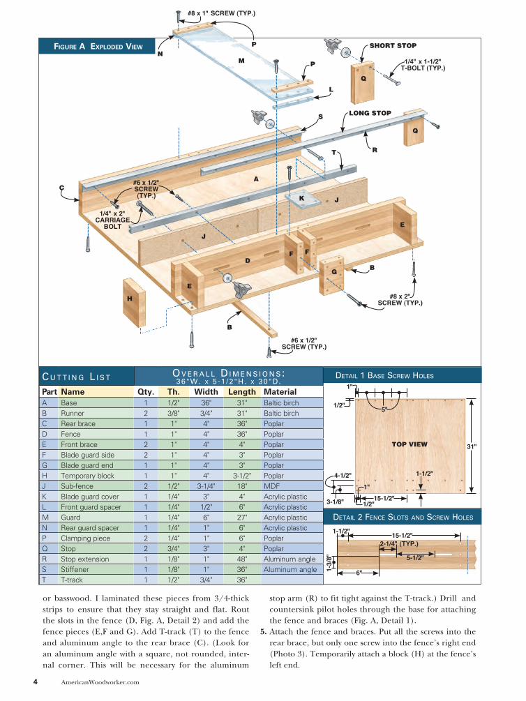
Figure A exploded View
or basswood. I laminated these pieces from 3/4-thick strips to ensure that they stay straight and flat. Rout the slots in the fence (D, Fig. A, Detail 2) and add the fence pieces (E,F and G). Add T-track (T) to the fence and aluminum angle to the rear brace (C). (Look for an aluminum angle with a square, not rounded, inter-nal corner. This will be necessary for the aluminum
stop arm (R) to fit tight against the T-track.) Drill and countersink pilot holes through the base for attaching the fence and braces (Fig. A, Detail 1).
5. Attach the fence and braces. Put all the screws into the rear brace, but only one screw into the fence’s right end (Photo 3). Temporarily attach a block (H) at the fence’s left end.
#8 x 1" SCREW (TYP.)
NP
PM
L
S
Q
Q
RT
J
D
E
K
1/4" x 1-1/2" T-BOLT (TYP.)
C
BG
F F
B
E
H
J
A
#8 x 2" SCREW (TYP.)
#6 x 1/2" SCREW (TYP.)
1/4" x 2" CARRIAGE
BOLT
#6 x 1/2" SCREW(TYP.)
LONG STOP
SHORT STOP
Detail 2 Fence SlotS anD Screw HoleS
Detail 1 BaSe Screw HoleS
5"
31"
1"
1/2"
4-1/2" 1-1/2"
3-1/8"
1"
1/2"
1-1/2"
1-3/
8"
15-1/2"
6"
5-1/2"
2-1/4" (TYP.)15-1/2"
c u t t i n g l i S t
Part Name Qty. Th. Width Length MaterialA Base 1 1/2" 36" 31" Baltic birch B Runner 2 3/8" 3/4" 31" Baltic birch C Rear brace 1 1" 4" 36" PoplarD Fence 1 1" 4" 36" PoplarE Front brace 2 1" 4" 4" PoplarF Blade guard side 2 1" 4" 3" PoplarG Blade guard end 1 1" 4" 3" PoplarH Temporary block 1 1" 4" 3-1/2" PoplarJ Sub-fence 2 1/2" 3-1/4" 18" MDFK Blade guard cover 1 1/4" 3" 4" Acrylic plasticL Front guard spacer 1 1/4" 1/2" 6" Acrylic plasticM Guard 1 1/4" 6" 27" Acrylic plasticN Rear guard spacer 1 1/4" 1" 6" Acrylic plasticP Clamping piece 2 1/4" 1" 6" PoplarQ Stop 2 3/4" 3" 4" PoplarR Stop extension 1 1/8" 1" 48" Aluminum angleS Stiffener 1 1/8" 1" 36" Aluminum angleT T-track 1 1/2" 3/4" 36"
o v e r a l l D i m e n S i o n S : 36"w. x 5 -1 /2"H. x 30"D.
TOP VIEW
AmericanWoodworker.com 5
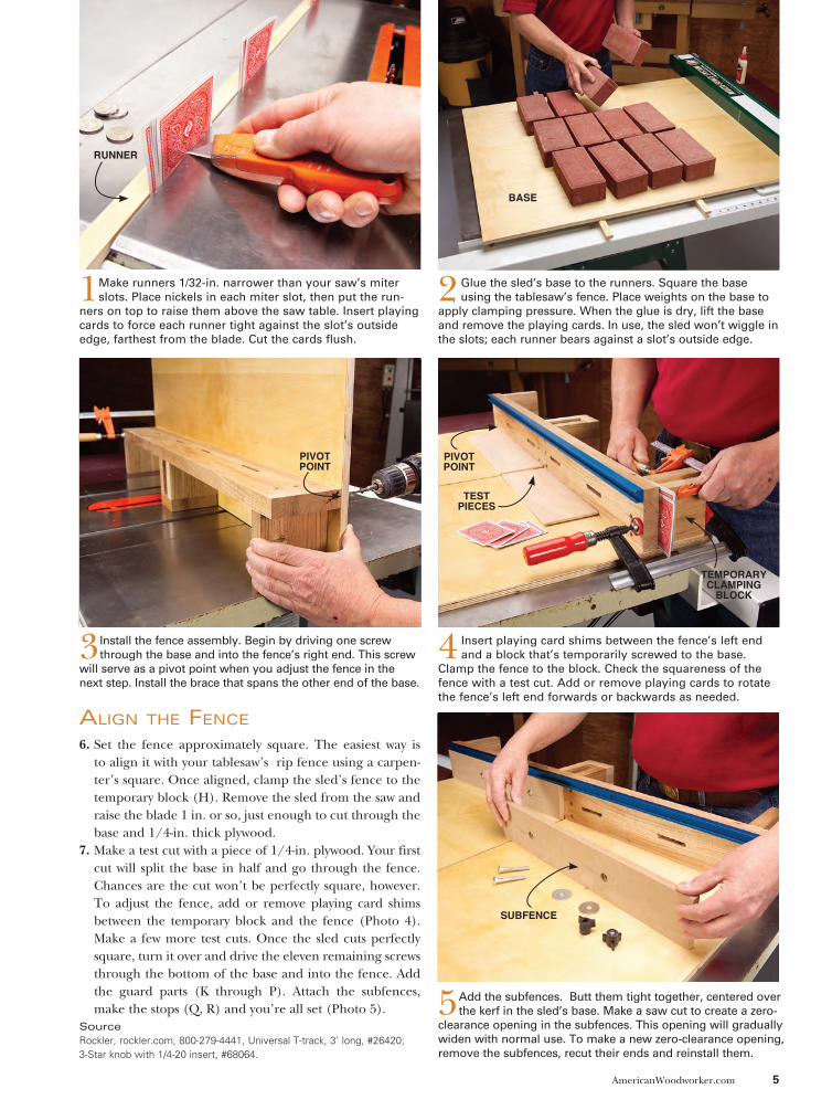
aligN the FeNce
6. Set the fence approximately square. The easiest way is to align it with your tablesaw’s rip fence using a carpen-ter’s square. Once aligned, clamp the sled’s fence to the temporary block (H). Remove the sled from the saw and raise the blade 1 in. or so, just enough to cut through the base and 1/4-in. thick plywood.
7. Make a test cut with a piece of 1/4-in. plywood. Your first cut will split the base in half and go through the fence. Chances are the cut won’t be perfectly square, however. To adjust the fence, add or remove playing card shims between the temporary block and the fence (Photo 4). Make a few more test cuts. Once the sled cuts perfectly square, turn it over and drive the eleven remaining screws through the bottom of the base and into the fence. Add the guard parts (K through P). Attach the subfences, make the stops (Q, R) and you’re all set (Photo 5).
2 Glue the sled’s base to the runners. Square the base using the tablesaw’s fence. Place weights on the base to
apply clamping pressure. When the glue is dry, lift the base and remove the playing cards. In use, the sled won’t wiggle in the slots; each runner bears against a slot’s outside edge.
3 Install the fence assembly. Begin by driving one screw through the base and into the fence’s right end. This screw
will serve as a pivot point when you adjust the fence in the next step. Install the brace that spans the other end of the base.
4 Insert playing card shims between the fence’s left end and a block that’s temporarily screwed to the base.
Clamp the fence to the block. Check the squareness of the fence with a test cut. Add or remove playing cards to rotate the fence’s left end forwards or backwards as needed.
5Add the subfences. Butt them tight together, centered over the kerf in the sled’s base. Make a saw cut to create a zero-
clearance opening in the subfences. This opening will gradually widen with normal use. To make a new zero-clearance opening, remove the subfences, recut their ends and reinstall them.
SourceRockler, rockler.com, 800-279-4441, Universal T-track, 3’ long, #26420; 3-Star knob with 1/4-20 insert, #68064.
1Make runners 1/32-in. narrower than your saw’s miter slots. Place nickels in each miter slot, then put the run-
ners on top to raise them above the saw table. Insert playing cards to force each runner tight against the slot’s outside edge, farthest from the blade. Cut the cards flush.
RUNNER
BASE
PIVOT POINT
PIVOT POINT
TEST PIECES
TEMPORARY CLAMPING
BLOCK
SUBFENCE