Cross Sections and Headroom (including Amendment … · Cross Sections and Headroom (including...
38
Cross Sections and Headroom (including Amendment No. 1, dated December 2014) DN-GEO-03036 April 2014 Design Standards DN
Transcript of Cross Sections and Headroom (including Amendment … · Cross Sections and Headroom (including...

Cross Sections and Headroom (including Amendment No. 1, dated December 2014)
DN-GEO-03036 April 2014
Design Standards DN

TRANSPORT INFRASTRUCTURE IRELAND (TII) PUBLICATIONS
About TII Transport Infrastructure Ireland (TII) is responsible for managing and improving the country’s national road and light rail networks. About TII Publications TII maintains an online suite of technical publications, which is managed through the TII Publications website. The contents of TII Publications is clearly split into ‘Standards’ and ‘Technical’ documentation. All documentation for implementation on TII schemes is collectively referred to as TII Publications (Standards), and all other documentation within the system is collectively referred to as TII Publications (Technical). This system replaces the NRA Design Manual for Roads and Bridges (NRA DMRB) and the NRA Manual of Contract Documents for Road Works (NRA MCDRW). Document Attributes Each document within TII Publications has a range of attributes associated with it, which allows for efficient access and retrieval of the document from the website. These attributes are also contained on the inside cover of each current document, for reference. For migration of documents from the NRA and RPA to the new system, each current document was assigned with new outer front and rear covers. Apart from the covers, and inside cover pages, the documents contain the same information as previously within the NRA or RPA systems, including historical references such as those contained within NRA DMRB and NRA MCDRW. Document Attributes
TII Publication Title Cross Sections and Headroom (including Amendment No. 1, dated December 2014)
TII Publication Number
DN-GEO-03036
Activity Design (DN) Document Set Standards
Stream Geometry (GEO) Publication Date April 2014
Document Number
03036 Historical Reference
NRA TD 27
NRA DMRB and MCDRW References For all documents that existed within the NRA DMRB or the NRA MCDRW prior to the launch of TII Publications, the NRA document reference used previously is listed above under ‘historical reference’. The TII Publication Number also shown above now supersedes this historical reference. All historical references within this document are deemed to be replaced by the TII Publication Number. For the equivalent TII Publication Number for all other historical references contained within this document, please refer to the TII Publications website.

Volume 6 Section 1
Part 2
NRA TD 27/14
Cross-sections and Headroom (including
Amendment No. 1, dated December 2014)
April 2014
St. Martin’s House, Waterloo Road, Dublin 4 Tel: +353 1 660 2511 Fax +353 1 668 0009
Email: [email protected] Web: www.nra.ie

Summary:
This Standard sets out the dimensional requirements for road cross-sections for all-purpose roads and
motorways. It covers the requirements on the open road and at structures, but not in tunnels. It also
gives requirements for headroom at structures.
Published by National Roads Authority, Dublin 2014

NRA DESIGN MANUAL FOR ROADS AND BRIDGES
April 2014 i
VOLUME 6 ROAD GEOMETRY
SECTION 1 LINKS
PART 2
NRA TD 27/14
CROSS SECTIONS AND HEADROOM
Contents
Chapter
1. Introduction
2. Design Principles
3. Cross-sections on Open Roads
4. Cross-sections at Structures
5. Headroom at Structures
6. References
7. Enquiries
Amendment No. 1

National Roads Authority Volume 6 Section 1
Design Manual for Roads and Bridges Part 2 NRA TD 27/14
(including Amendment No. 1)
April 2014 1
1. INTRODUCTION
General
1.1 This Standard outlines the design principles and factors which should be considered by Design
Organisations in selecting road cross-sections and headroom. The process of design is described
together with an approach to developing options.
1.2 This standard supersedes the November 2011 version of NRA TD 27. This standard is a general
revision including the introduction of:
a) The requirement to provide mandatory Cycle facilities in accordance with TD 300 and
RCD Series 000 has resulted in amendments to the following sections:
i) Section 1.10 Definitions
ii) Par 2.7, 2.13, 2.14, 2.15, 2.17, 2.22, 2.25
iii) Par 3.4, 3.29, 3.34, 3.37, 3.41, 3.59, 3.60
iv) Table 1
v) Table 3
vi) Par 4.1, 4.9, 4.14, 4.15
vii) Table 6
viii) Par 5.6
b) Black boxes have been removed resulting in paragraph 1.11 being amended.
Scope
1.3 This Standard gives details of the cross-sections and headroom clearances to be used for all-purpose
roads and motorways, both on open roads and at structures.
1.4 The information covers roads of all types: rural motorways, rural all-purpose roads, urban
motorways, urban all-purpose roads together with associated connector roads.
1.5 This Standard is not applicable to road tunnels.
1.6 For details of pedestrian and cycle subway dimensions see TD 36, and for footbridges see BD 29.
Advice on equestrian subways and for agricultural crossings is given in TA 57.
Implementation
1.7 This Standard should be used forthwith for all schemes for the construction and/or improvement of
all-purpose roads and motorways. The Standard should be applied to the design of schemes already
being prepared unless, in the opinion of the National Roads Authority, application would result in
significant additional expense or delay progress. In such cases, Design Organisations should confirm
the application of this Standard to particular schemes with the National Roads Authority. For minor
improvements to existing roads refer to NRA TA 85/11.
1.8 For the application of this Standard to regional and local roads diverted or improved on-line as part
of a national road scheme, see Paragraphs 3.3 and 4.4.

National Roads Authority Volume 6 Section 1
Design Manual for Roads and Bridges Part 2 NRA TD 27/14
(including Amendment No. 1)
April 2014 2
Definitions
1.9 For the definitions of the general road terms used in this Standard such as components of the road
(central reserve, verge, hard shoulder, and hard strip, etc.) see BS 6100-1 and BS 6100-4.
1.10 Particular terms used in this Standard are defined as follows:
a) All-purpose road: - A road for the use of all classes of traffic (e.g. not a motorway).
b) Bridge Length: - is the length of bridge parapet. Long underbridges are those exceeding
100m.
c) Bridleway: - Road (surfaced or unsurfaced) for use on foot or horseback.
d) Central reserve: - The area which separates the carriageways of a dual carriageway or
Motorway. Note that this includes any offside hard strips.
e) Connector Road: - A collective term for slip roads, interchange links and loop roads.
f) Cross-section: - The road cross-section incorporates all elements between the boundaries
including carriageways, the central reserve, separation zones, hard shoulders, hard strips,
verges including any footway, cycle track or bridleway, cutting or embankment slopes,
berms and work space. All dimensions are measured square to the line of the road (see
Tables 2 to 5).
g) Cycle Track: - Part of a road, including part of a footway or part of a roadway, which is
reserved for the use of pedal cycles and from which all mechanically propelled vehicles,
other than mechanically propelled wheelchairs, are prohibited from entering except for the
purpose of access.
h) Cycle Facilities: - refers to all types of measures which improve conditions for cyclists and
include:
i) Cycleways
ii) Cycle Tracks
iii) Cycle Lanes
iv) Shared Cycle Tracks with Pedestrians
v) Shared roads with Motor Vehicles under low speed/low traffic flow conditions.
i) D2M: - Dual two-lane motorway.
j) Design Organisation: – The organisation responsible for undertaking and/or certifying the
design.
k) Designated Lane: - A lane reserved exclusively for the use by designated vehicles such as
cycles, buses and taxis.
l) Disabled People: - Includes individuals with mobility, sight, comprehension or hearing
impairment, the ageing population and people with temporary injuries. Includes users of
wheelchairs (manual and electric) as well as users of motorised mobility scooters.
m) Footway:- that portion of any road associated with a roadway which is provided
primarily for use by pedestrians;

National Roads Authority Volume 6 Section 1
Design Manual for Roads and Bridges Part 2 NRA TD 27/14
(including Amendment No. 1)
April 2014 3
n) Hardened Verge:- An area of the verge set aside for emergency situations for vehicles to
stand or park. The surface should be sufficiently strengthened to support vehicles safely
without sinking into the surface.
o) Headroom: - The minimum distance between surface and structure as defined in
Paragraph 5.5.
p) Interchange: - A grade separated junction that provides free flow of traffic from one
mainline carriageway to another. Refer to TD 22.
q) Interchange Link: - Refer to TD 22.
r) Loops: - Refer to TD 22.
s) Mainline: - The carriageway carrying the main flow of traffic (generally traffic passing
straight through a junction or interchange).
t) Maintaining Organisation: - The organisation which will be responsible for the
maintenance of the road after construction.
u) Maintained Headroom: - The minimum headroom which shall be preserved at all times.
v) Nearside: - Left-hand side of vehicle when viewing a forward moving vehicle from
behind: typically the front-seat passenger side of the vehicle in Ireland.
w) New Construction Headroom: - The headroom which includes an allowance for
resurfacing.
x) Non-motorised Users (NMUs): - Pedestrians, cyclists and equestrians, including disabled
people (see definition of ‘Disabled People’) and other mobility impaired users (e.g. people
with luggage, with children, or pregnant women).
y) Offside: - Right-hand side of vehicle when viewing a forward moving vehicle from
behind: typically the driver’s side of the vehicle in Ireland.
z) Overbridge: - A bridge that spans the road under consideration.
aa) Pedestrian Access Provision: - That part of the verge on all-purpose roads provided to
enable pedestrian movement through or over a structure.
bb) Road Authority: - The authority responsible for the road construction or improvement
scheme.
cc) Road Tunnel: - A road tunnel enclosed for a length of 150m or more. A shorter enclosed
length is an overbridge. Refer to NRA BD 2.
dd) Rural Road:- A road outside of built-up areas including i) a single carriageway with a
mandatory speed limit of at least 80km/h; or ii) a single carriageway within a speed
transition zone and with a mandatory speed limit of 60km/h; or iii) a dual carriageway with
a mandatory speed limit of at least 100km/h; or iv) a Motorway with a mandatory speed
limit of 120km/h.
ee) Separator Zone: - An area that separates traffic flows on the mainline from an adjacent
parallel road, e.g. link road.
ff) S2: - Two-lane single carriageway road with lane widths of up to 3.65m).
gg) Slip Road: - Refer to TD 22.
hh) Subway: - Underground passageway or tunnel for use by pedestrians, cyclists and
sometimes equestrians.
ii) Type 1 Dual Carriageway: - A divided all-purpose road with two lanes in each direction
constructed to the geometric standards of NRA TD 9 and TD 22.

National Roads Authority Volume 6 Section 1
Design Manual for Roads and Bridges Part 2 NRA TD 27/14
(including Amendment No. 1)
April 2014 4
jj) Type 2 Dual Carriageway: - A divided all-purpose road with two lanes in each direction
constructed to the geometric standards of NRA TD 10, NRA TD 300 and Road
Construction Details Series 000.
kk) Type 3 Dual Carriageway: - A divided all-purpose road with two lanes in one direction of
travel and one lane in the other direction, constructed to the geometric standards of NRA
TD 10, NRA TD 300 and Road Construction Details Series 000. The two-lane section
alternates with a one-lane section at intervals of 2km approximately.
ll) Type 1 Single Carriageway:- An all-purpose road with a 3.65m lane in each direction
constructed to the geometric standards of NRA TD 9.
mm) Type 2 Single Carriageway:- An all-purpose road with a 3.50m lane in each direction
constructed to the geometric standards of NRA TD 9, NRA TD 300 and Road Construction
Detail Series 000.
nn) Type 3 Single Carriageway:- An all-purpose road with a 3.00m lane in each direction
constructed to the geometric standards of NRA TD 9, NRA TD 300 and Road Construction
Detail Series 000.
oo) Underbridge: - A bridge that carries the road under consideration.
pp) Urban Road:- A road within a built-up area including i) a single carriageway urban relief
road with a mandatory speed limit of 60km/h; or ii) a dual carriageway with a mandatory
speed limit of 80km/h or less; or iii) a Motorway with a mandatory speed limit of 100km/h
or less.
qq) Urban Relief Road:- An urban road where the primary purpose of the road is to facilitate
the movement of traffic and avoid congestion or other obstacles to movement.
rr) Urban Street:- A road within a built-up area with a mandatory speed limit of 50km/h or
less; or a road within a built-up area with a mandatory speed limit of 60km/h and where the
primary purpose of the road is to provide direct access to premises.
ss) Verge: - The part of a road cross-section alongside a carriageway but not including
embankment or cutting slopes. Note that this includes hard strips but not hard shoulders.
tt) Work Space: -The strip of land between the top of cutting or toe of embankment and the
road boundary.
Relaxations and Departures
1.11 The standards contained in this document represent the Cross-sections and Headroom whose
incorporation in the design would achieve a desirable level of performance in average conditions
in terms of traffic safety, operation, economic and environmental effects and sustainability. At
some locations on new roads or major improvements, however, it may not be possible to justify
even the lowest levels of design parameters in economic or environmental terms, due to high
costs, low traffic levels, and environmental damage, etc. In such cases, sufficient advantages
might justify either a Relaxation within the standards or, in more constrained locations, a
Departure from the standards. Relaxations and Departures should be assessed in terms of their
effects on the economic worth of the scheme, the environment, and the safety of the road user.
Further details on the use of Relaxations and Departures are as follows.
Relaxations within Standard
1.12 In difficult circumstances, the Design Organisation may relax a standard set out in this document,
where specifically provided for within the text. Refer to NRA TD 9. The Design Organisation shall
record the fact that a Relaxation has been used in the design and the corresponding reasons for its
use. The record shall be endorsed by the Design Organisation’s senior engineer responsible for the

National Roads Authority Volume 6 Section 1
Design Manual for Roads and Bridges Part 2 NRA TD 27/14
(including Amendment No. 1)
April 2014 5
scheme. The Design Organisation shall report all Relaxations incorporated into the design as part of
the project report at the end of each project management phase (refer to the National Roads Project
Management Guidelines).
Departures from Standards
1.13 In exceptional situations, the National Roads Authority may be prepared to agree to a Departure
from Standards where the standard, including permitted Relaxations, is not realistically achievable.
Design Organisations faced by such situations and wishing to consider pursuing this course shall
discuss any such option at an early stage in design with the National Roads Authority. Proposals to
adopt Departures from Standard must be submitted by the Design Organisation to the National
Roads Authority and formal approval received BEFORE incorporation into a design layout.

National Roads Authority Volume 6 Section 1
Design Manual for Roads and Bridges Part 2 NRA TD 27/14
(including Amendment No. 1)
April 2014 6
2. DESIGN PRINCIPLES
General
2.1 This section describes the principles to be followed when designing road cross-sections for new and
improved all-purpose roads and motorways. The underlying principle is that Design Organisations
are given the maximum choice, so that there is flexibility to develop layout options that will meet the
National Roads Authority’s objectives.
2.2 Design Organisations should balance considerations of safety, environmental impact, sustainability,
cost, buildability of the road elements, operation and maintenance. Where there are options for
heights or widths, the selection process should include due consideration of these factors and any
other design constraints.
Health & Safety Responsibilities
2.3 When selecting the most appropriate carriageway type, including connector roads, for a new or
improved road, consideration should be given to the construction of and future maintenance and
operation of the road. Health and Safety legislation requires that consideration is taken to ensure that
the scheme can be constructed safely. The legislation also requires that consideration be given at the
design stage to the safety of maintenance operations and the safety of all who may be required to
work on or near the road in the course of their duties, e.g. emergency service personnel. In certain
circumstances, when selecting the cross-section, the Design Organisation may need to:
a) enhance particular cross-sectional components along a whole route or link;
b) provide localised widening of standard cross-sections; or
c) select a higher standard of carriageway than suggested on traffic grounds.
2.4 Design Organisations must consider maintenance issues on a scheme-by-scheme basis and the
selection of standard cross-sections in this Standard does not obviate the need for such
considerations. The Design Organisation must compile a statement of scheme specific maintenance
and health and safety issues ensuring that all maintenance activities are considered. The Design
Organisation must consult with the Maintaining Organisation when compiling this statement. The
Design Organisation must recommend the most appropriate cross-section to the Road Authority and
must agree the timing of such recommendations at the outset of the scheme. This paragraph does not
relieve Design Organisations of their statutory health and safety responsibilities.
Range of Choice
2.5 The widths of paved elements of the cross-section, i.e. running lanes, hard shoulders and hard strips,
vary between different types of road. Dimensions have been selected on the basis of research,
experience in Ireland, and comparison with other countries’ standards, in order to give new and
improved roads that maximise safety and are operationally efficient and cost effective. The Design
Organisation is not given choices over the widths of running lanes, hard shoulders and hard strips for
a particular type of road.
2.6 The Design Organisation does, however, have some flexibility over the width of work space, berms,
side slopes, verges and central reserves, although a reduction of verge or central reserve width below
desirable minimum will require a Departure.

National Roads Authority Volume 6 Section 1
Design Manual for Roads and Bridges Part 2 NRA TD 27/14
(including Amendment No. 1)
April 2014 7
2.7 The verge width on either side of the paved area may be a factor affecting the severity of accidents
where vehicles run off the carriageway. Research has indicated that only a small proportion of injury
accidents, perhaps 2% or 3% in open country, would be avoided if verges were to be doubled in
width. Consequently, safety aspects will not normally be a factor when choosing a verge width
greater than the desirable width, provided visibility requirements are met. Details of when to provide
safety barriers in verges and central reserves to protect against collisions between vehicles and
roadside objects or features are given in NRA TD 19. Details of mandatory cycle facility widths
which shall be accommodated in the verge width of Type 2 and Type 3 Single and Dual Carriageway
Roads are included in NRA TD 300 and RCD’s 000/2 to 000/5.
2.8 The width between the back of the verge and the road boundary will depend on the terrain, the need
to accommodate environmental mitigation measures, the engineering or geotechnical measures used
to accommodate changes in ground levels, and any need to include differing types and widths of
drain and other services in the work space.
Environmental Design
2.9 Environmental design features are an integral aspect of the design of any road and many features can
have a significant effect on the required overall width of the road.
Network Objectives
2.10 The aim is to deliver an economic, accessible, integrated, safe, reliable, sustainable, efficient and
environmentally acceptable network for all users. This includes the need for safe, efficient and
effective maintenance as well as the necessity to adapt and improve some roads for the benefit of
non-motorised users. The Design Organisation should take these factors into account throughout the
design process.
Designated Lanes
2.11 With integrated and sustainable transport policy now guiding transport planning, the need to consider
and accommodate bus facilities and other designated lanes within the cross-section is likely to
increase. The reallocation of road space to buses and other designated vehicles can greatly improve
journey times and reliability, thereby encouraging modal shift.
2.12 In many instances the provision of a designated lane will be achieved through the adaptation of the
existing carriageway, especially in urban areas. This will often result in a lane being lost for general-
purpose traffic. The Road Authority should therefore be fully satisfied of the net benefits to be
derived from any proposed alterations. It is important to consider these aspects at an early stage in
the project appraisal so as to ensure the most sustainable use of the road network.
2.13 The Design Organisation must ensure that the proposed cross-section and lane widths are adequate to
enable maintenance to be undertaken safely. Care must be taken to ensure that where cyclists are
permitted to use the designated lane, the width is adequate for this purpose. Details of mandatory
cycle facility widths for Type 2 and Type 3 Single and Dual Carriageway Roads are provided in
NRA TD 300 and RCD’s 000/2 to 000/5.
2.14 Any proposal to install a designated lane on a national road is a Departure from Standard except
where mandatory cycle facilities are required on Type 2 and 3 Single and Dual Carriageway Roads.

National Roads Authority Volume 6 Section 1
Design Manual for Roads and Bridges Part 2 NRA TD 27/14
(including Amendment No. 1)
April 2014 8
Non-Motorised Users
2.15 It is essential that Design Organisations integrate facilities for non-motorised users (NMUs) in the
design at an early stage so that they are not overlooked when allocating space. This will help to
ensure the most sustainable cross-section is selected. To do this effectively, Design Organisations
must be able to understand the road environment from the NMUs’ perspective and the relationship of
NMUs to the various road design components. The Design Organisation shall provide the cycle
facility widths described in NRA TD 300 and RCD’s 000/2 to 000/5.
2.16 During project appraisal involving new construction or improvement of an existing road, Design
Organisations must determine and make adequate provision for any NMU requirements. An effective
way of achieving this is through consultation with user groups.
2.17 The Design Organisation’s attention is drawn to the requirement to provide proper and sufficient
footways for pedestrians, cycle facilities and adequate margins for ridden horses and driven livestock
where it is considered necessary, or desirable, for the safety or accommodation of these road users.
2.18 In general, this will be the case for online improvements of national roads where no safer alternative
route is available. However NMUs should be discouraged from using new offline high-speed roads
where the existing route remains available and provides a safer alternative.
Disabled Persons
2.19 Disabled persons are better able to participate in the community if suitable and accessible facilities
are available that make it easier for them to reach their desired destinations, especially for those that
do not drive. Suitable provision is therefore an essential component of the cross-section because it
allows greater independence for disabled persons.
2.20 Design Organisations are required to take necessary measures to ensure no discrimination on the
basis of disability when considering the design of roadside features.
2.21 The required standard of provision for persons with disabilities must be considered at the early stages
of scheme preparation and the level of facilities must be agreed with the Road Authority (Refer to
paragraph 3.59).
Design Process
2.22 For the purposes of developing initial layouts, the Design Organisation’s objective should be to
determine the appropriate width for the road cross-section, and any variation in width required.
Features included in the cross-section can affect the choice of width. Features that commonly occur
within the road may include:
a) Agricultural cattle/horse crossings;
b) Animal tunnels;
c) Anti-dazzle fences;
d) Apparatus of utility companies and other authorities;
e) Bridleways;
f) Communication equipment;
g) Cycle Facilities;
h) Culverts;

National Roads Authority Volume 6 Section 1
Design Manual for Roads and Bridges Part 2 NRA TD 27/14
(including Amendment No. 1)
April 2014 9
i) Drains;
j) Emergency telephones;
k) Fencing;
l) Footbridges;
m) Footways;
n) Foundations;
o) Garda observation platforms;
p) Geotechnical monitoring equipment;
q) Geotextiles;
r) Hardened Verge;
s) Landscaping;
t) Lay-bys;
u) Lighting columns;
v) Loop detectors;
w) Noise barriers / bunding;
x) Overbridges;
y) Parapets;
z) Pedestrian guardrails;
aa) Retaining walls;
bb) Safety barriers;
cc) Sign/signal gantries;
dd) Subways;
ee) Tracks for equestrians;
ff) Traffic signals and control and equipment;
gg) Traffic signs;
hh) Underbridges;
ii) Vehicle arrester beds;
jj) Visual barriers / bunding; and
kk) Weather monitoring equipment.
2.23 Details and design requirements for many of these features are contained in the Standards and
Advice Notes of the NRA Design Manual for Roads and Bridges and in various other documents.
Some features, safety barriers and large traffic signs for example, can have a significant effect on the
cross-section width whilst other features, sign gantries for example, are usually accommodated
within the side slopes and work space.

National Roads Authority Volume 6 Section 1
Design Manual for Roads and Bridges Part 2 NRA TD 27/14
(including Amendment No. 1)
April 2014 10
2.24 The preferred locations for features in verges and the central reserve may often coincide or overlap,
and the Design Organisation should be aware of the potential for such conflicts. Generally, there is
far more below the surface of verges and central reserves than is apparent on the surface, and some
underground features must be readily accessible for routine maintenance purposes. Engineering
solutions can usually be designed to overcome conflicts where space is limited, but these may
increase costs. The sizes and extents of features above and below ground in the verge and central
reserve of rural roads can vary widely. Therefore, details are best designed individually for each
situation.
Visibility
2.25 On curved alignments and approaches to junctions, it may be necessary to widen the cross-section,
particularly verges and central reserves, to ensure that drivers and other road users can see the
appropriate distances, and that the layout meets the visibility requirements. Refer to NRA TD 9 and
NRA TD 300.

National Roads Authority Volume 6 Section 1
Design Manual for Roads and Bridges Part 2 NRA TD 27/14
(including Amendment No. 1)
April 2014 11
3. CROSS-SECTIONS ON OPEN ROADS
General
3.1 Tables 2 to 5 give detailed dimensions for each element. The information covers most types of road,
including rural motorways, rural all-purpose roads, urban motorways and urban all-purpose dual
carriageway roads, together with associated interchange links, loops and on and off slip roads. For
graphic representations of these cross-sections, refer to NRA Road Construction Details Series 000.
3.2 Wide Motorway cross-sections will normally be used only where adjacent lengths of road are of
equivalent cross-section. The use of these cross-sections shall be agreed with the National Roads
Authority in each case.
3.3 Table 3 gives detailed dimensions for each element of the cross-sections for regional and local roads
diverted or improved on-line as part of a national road scheme. The particular type of cross-section
to be adopted shall be a Type 1, 2 or 3 depending on the predicted traffic flows and the resulting
capacity level to be provided in accordance with NRA TD 9 Table 6/1.
For graphic representations of these cross-sections, refer to NRA Road Construction Details Series
000.
Pavement Width
3.4 The width of the paved elements of the cross-section, i.e. carriageways, hard shoulders and hard
strips, shall be in accordance with the requirements of this Standard. Any reduction or increase in the
width of these elements is a Departure from Standard, unless the increase results from the
requirements of Paragraph 3.8, NRA TD 9 or NRA TD 300.
Traffic Lane Widths
3.5 Traffic lane widths are measured between the trafficked side of carriageway edge lines and the centre
line of lane lines and shall be as detailed in Tables 2 to 5.
3.6 Where kerbs are used on roads with a speed limit above 80km/h they shall be a maximum height of
80mm and shall be splayed over the full height, by at least 45° to the vertical.
3.7 Information on the provision, start and finish of climbing lanes incorporated into single and dual
carriageway roads can be found in NRA TD 9.
3.8 Traffic lanes shall be widened on curves of low radius to allow for the swept path of long vehicles.
See NRA TD 9.
Changes of Carriageway Edge Treatment
3.9 Where slip roads, interchange links and loop roads join or leave main carriageways, the edge detail
may change from hard shoulder to hard strip or carriageway edge.
3.10 Transitions between different edge details should take place over the length of the taper.
3.11 See NRA TD 10, TD 22, TD 40 and NRA TD 41-42 for the layouts of merges and diverges at
junctions and accesses.

National Roads Authority Volume 6 Section 1
Design Manual for Roads and Bridges Part 2 NRA TD 27/14
(including Amendment No. 1)
April 2014 12
Hard Strips
3.12 A hard strip provides a surfaced strip that abuts on the traffic lanes. The key reasons for the provision
of hard strips include:
a) pavement integrity/stability;
b) partial, cost-effective provision for stopped vehicles;
c) provision of valuable additional width to accommodate temporary traffic management
layouts;
d) snow and water collection;
e) overrun facility for driver error or evasive action; and
f) improved level of service and driver comfort.
3.13 The hard strip also supports edge lines, reduces the risk of vegetation encroachment over edge lines
and allows for the placement of road studs outside vehicle wheel paths, where appropriate.
3.14 Hard strips on urban roads are not normally provided due to the associated constraints on land-take
and land costs. Urban roads have lower design speeds and are often more congested than those in
rural areas. Generally drivers do not expect rural standards in urban areas - the restriction of width of
the road makes drivers more aware of NMUs and can assist with encouragement of low speeds,
which is of safety benefit due to the large number of accesses and NMUs. On urban roads the
carriageway edge treatment will generally include positive drainage and kerbs, which provides
additional edge restraint and support for raised footways and verges.
Hard Shoulders
3.15 The hard shoulder is provided adjacent to the nearside of the traffic lanes to offer a place to stop in
emergencies, clear of mainline traffic. It also provides access for emergency vehicles and additional
road space during temporary traffic management. On all-purpose single carriageways, the hard
shoulder also provides safe areas for slow moving vehicles to pull over to allow other traffic to
overtake.
3.16 Offside hard shoulders are not permitted.
Central Reserves
3.17 Central reserves provide physical separation between carriageways thereby providing freedom from
interference from opposing traffic, particularly where a safety barrier is provided.
3.18 Minimum central reserve widths are given in Tables 2 to 5. A central reserve width less than the
minimum is a Departure from Standard.
3.19 Greater dimensions may be used in circumstances where this would be preferable. The standard
widths are based on the assumption that the road alignment is straight and level between
carriageways and that only a minimal amount of equipment or street furniture needs to be
accommodated, either permanently or during temporary maintenance activities. The Design
Organisation should consider whether it is necessary to widen the central reserve in order to:
a) provide the requisite stopping sight distances in accordance with NRA TD 9;
b) accommodate any street furniture, utility or drainage features and equipment;
c) meet the requirements of NRA TD 19 for safety barriers;

National Roads Authority Volume 6 Section 1
Design Manual for Roads and Bridges Part 2 NRA TD 27/14
(including Amendment No. 1)
April 2014 13
d) accommodate any permanent signs required, with particular attention to the provision of
adequate working width and set-back for safety barriers relative to the complete sign
assembly;
e) accommodate significant difference in levels of adjacent carriageways;
f) accommodate temporary traffic management layouts for the envisaged maintenance
regime;
g) accommodate variable message signs and signals;
h) accommodate any parts of structures or complete structures;
i) provide sufficient space for maintenance operations;
j) fulfil landscape and environmental objectives; and
k) accommodate NMUs.
3.20 The Design Organisation should consider other features that may have to be accommodated in the
central reserve, some of which are listed in Paragraph 2.22 and also the health and safety
responsibilities highlighted in Paragraphs 2.3 and 2.4. During project appraisal the Design
Organisation should also ensure that future network plans for traffic control (e.g. gantries) are taken
into account.
3.21 Variations of central reserve widths in close succession should be avoided. The Design Organisation
should consider how the scheme will integrate with adjacent highway sections and the route as a
whole.
3.22 Where the central reserve width varies, raised profile markings should be used to define the edge of
the running lane clearly. Particular care should be taken to avoid creating the illusion of a lane gain,
for example, by the use of coloured surfacing to distinguish the widened area and maintain a constant
width of hard strip. Furthermore, variations in safety barrier set back should be carefully considered
in this regard to provide a flowing appearance.
3.23 Reference should be made to NRA TD 41-42 and NRA TD 10 for guidance on widening the central
reserve at priority junctions on Type 3 Dual-Carriageway all-purpose roads. Away from junctions,
crossing places for NMUs should be avoided on dual carriageway all-purpose roads. Where there is
sufficient demand for a crossing point, provision of an underpass or pedestrian overbridge should be
considered. A flow of about 10 pedestrians in any hour may warrant such a provision, and this will
need to consider step-free access options to accommodate all NMUs.
Emergency Crossing Points
3.24 NRA TD 9 provides advice on the design of Emergency Crossing Points.
Hardening of Central Reserves
3.25 Techniques for reducing maintenance liabilities within central reserves should be considered during
the preparation of new roads and improvements and also for major maintenance operations on
existing roads, to reduce risks to both operatives and other highway users. Such techniques may
include hardening or the planting of low growth species of grass.
3.26 For new construction schemes, central reserves shall be paved.

National Roads Authority Volume 6 Section 1
Design Manual for Roads and Bridges Part 2 NRA TD 27/14
(including Amendment No. 1)
April 2014 14
3.27 When deciding whether to harden existing central reserves as part of a road improvement /
maintenance scheme, Design Organisations should:
a) check the adequacy of the surface water drainage system;
b) make an assessment of environmental factors, such as the landscape character of the setting
and location of the road, the environmental consequences of weed control and the function
of the central reserve as a potential habitat. The environmental database for the route
should therefore be consulted;
c) determine the area to be hardened, based on what areas of vegetation may be left uncut
without affecting visibility or sign conspicuity;
d) take account of whole-life costs and safety considerations.
3.28 Any general hardening of the central reserve should be designed to be capable of withstanding light
vehicle over-run and prevent weed growth. The Road Authority should be consulted for advice on
the pavement specification.
Verges
3.29 The verge is important from a number of perspectives, including safety, the environment and when
considering the initial cost and ongoing maintenance and operating costs. It can provide a separate
route for NMUs on all-purpose roads and also offers an area to accommodate footways, cycle
facilities and other dedicated facilities to improve safety and convenience for these groups. On
motorways, stranded motorists may use the verge on foot to reach the emergency telephones or await
the arrival of a rescue vehicle. The design of the verge, as well as the location of the emergency
telephone, should consider the access requirements that may be required for some NMUs.
3.30 Minimum verge widths are given in Tables 2 to 5. A verge width less than the minimum is a
Departure from Standard. Note: Where the Tables denote ‘varies’, the decision rests with Design
Organisations, taking into account the advice in this Standard.
3.31 Advice concerning choice of verge width corresponds with that provided for central reserves in
Paragraphs 3.17 to 3.23. Additional advice solely for verges is given below.
3.32 NRA TD 19 provides requirements to ensure safety if a Safety Barrier is struck and deflected near
the edge of an embankment slope. Design Organisations must comply with NRA TD 19 and, where
necessary, for example on the approach to underbridges, additional verge width may need to be
provided.
3.33 Environmental fencing is becoming a regular feature of the cross-section and the Design
Organisation should establish the requirements as early as practicable in order to make appropriate
provision of road width.
3.34 Where it is necessary to accommodate communications ducting and chambers, a minimum verge
width of 2.0m shall be provided. On a Type 2 or 3 Dual Carriageway, a minimum verge width of
3.0m shall be provided in this regard.
3.35 The verge offers an important component in road drainage systems, including the storage of snow
displaced from the carriageway. It offers an area to support utility plant and to house highway
equipment. Congested verges with insufficient room for necessary roadside components present both
safety and engineering difficulties.
3.36 The concept of providing wide verges to slow and contain errant vehicles has significant land take
implications. Research has indicated that only a small proportion of injury accidents would be

National Roads Authority Volume 6 Section 1
Design Manual for Roads and Bridges Part 2 NRA TD 27/14
(including Amendment No. 1)
April 2014 15
avoided if verges were doubled in width. Consequently, vehicular safety aspects will not normally be
a factor when choosing a verge width greater than the minimum width, provided visibility
requirements are met and space exists for any safety barriers that may be required.
3.37 Verges should be sufficiently firm, level and free from hazards to permit their occasional use by
NMUs in the absence of dedicated facilities.
3.38 Variations of verge widths in close succession should be avoided. The Design Organisation should
consider how the scheme will integrate with adjacent highway sections and the route as a whole.
3.39 Provision for NMUs on all-purpose roads must be made where a local need has been identified and
agreed with the Road Authority.
3.40 Where footways are provided, the widths shall be in accordance with HD 39.
3.41 Cycle Facilities shall be provided within the verges of Type 2 and Type 3 Single and Dual
Carriageways. These shall be located beyond the edge of carriageway in accordance with NRA TD
300. For graphic representation of the above, refer to NRA Road Construction Details Series 000.
Work Space and Side Slope Widths
3.42 Work space and side slope widths should be chosen to suit the local situation. The width of work
space will depend upon:
a) terrain;
b) environmental design features;
c) engineering and geotechnical measures used to accommodate changes in ground levels;
d) the need to accommodate various types and widths of drain and other services in any work
space;
e) maintenance requirements.
3.43 The width of work space shall be determined by the Design Organisation. A typical width of 3.0m is
recommended.
3.44 Whenever practicable, side slopes adjacent to emergency roadside telephones should be kept to a
minimum angle to assist motorists in waiting at the road boundary in the event of an emergency or
breakdown.
Auxiliary Lane Provision
3.45 Where auxiliary lanes are provided in accordance with general arrangement layouts given in TD 22
and NRA TD 41-42, the width of the auxiliary lane(s) shall be equal to the width of the adjacent
nearside mainline lane.
3.46 The provision of either a hard shoulder or hard strip adjacent to an auxiliary lane shall be consistent
with the provision on the mainline.

National Roads Authority Volume 6 Section 1
Design Manual for Roads and Bridges Part 2 NRA TD 27/14
(including Amendment No. 1)
April 2014 16
Connector Road Lane Provision
3.47 For guidance on determining the required number of lanes, hard shoulder and hard strip provision on
connector roads, see TD 22.
3.48 Where connector roads approach junctions, those dimensions given in the relevant Standards that
prescribe safe and efficient junction designs may take precedence over the cross-section dimensions
given in this Standard. Traffic movements at the junction may demand the development of additional
lanes to provide capacity for separate traffic streams.
Separator Zones
3.49 The widths of separator zones should generally follow the decision-making process used to
determine central reserve widths discussed in Paragraphs 3.17 to 3.23 above. Design Organisations
should be aware that minimal width separator zones could lead to problems due to a lack of refuge
area for occupants of broken down vehicles and also for maintenance.
3.50 Where traffic on any lane of a parallel road runs counter to the mainline traffic flow, the risks
associated with headlight glare shall be assessed and the need for and the type of mitigation
measures shall be considered when determining the required width of separator zones.
3.51 Methods of avoiding headlight glare include:
a) designing the alignments of the roads so as to provide significant level differences;
b) providing screening fences or earth bunds;
c) providing appropriately designed soft planting that provides foliage all year round at the
correct heights;
d) where the use of a safety barrier is required, it may be practicable to provide a system that
is designed to cut off glare.
3.52 Design Organisations should take into consideration which mitigation method provides the most
sustainable solution.
3.53 Sightline requirements must not be compromised by the above measures.
Provision of Lay-bys
3.54 For guidance on determining the requirements for the provision of lay-bys, see NRA TA 69.
Road Markings
3.55 For details of the road markings required to define lanes, hard shoulders, etc. on the various types of
road cross-section, see the Traffic Signs Manual.
Urban Areas
3.56 Footways and off road cycle tracks provided on all-purpose roads in urban areas shall meet with the
width requirements given in Table 1.
3.57 Where it is anticipated that mobility impaired users will be regular users of a footway, consideration
shall be given to increasing the footway width to 1.80m

National Roads Authority Volume 6 Section 1
Design Manual for Roads and Bridges Part 2 NRA TD 27/14
(including Amendment No. 1)
April 2014 17
3.58 A kerbed raised verge width shall be provided which shall include the footway, off road cycle track
or shared facility widths in Table 1. This raised verge width shall also include a minimum
segregation width between the edge of carriageway and edge of footway, off road cycle track or
shared facility of 0.5m for Single Carriageway Roads and 1.5m for Dual Carriageway Roads. See
Road Construction Details Series 000 for a graphic representation.
3.59 In urban areas there may be numerous items of street furniture within the highway cross-section.
Rural Areas
3.60 Cycle facilities provided on Type 2 and Type 3 Single and Dual Carriageway Roads in rural areas
shall meet with the width requirements of NRA TD 300 and RCD’s 000/2 to 000/5.
Table 1: Minimum Verge, Footway and Off Road Cycle Track Widths on Urban/Rural Roads
Usage
Minimum Footway/ Off
Road Cycle Track Width
(m)
Minimum Verge Width
(m)
Footway
Regular usage1 1.65
Single Carriageway 2.15
Dual Carriageway 3.15
Footway
Occasional usage1 1.50
Single Carriageway 2.00
Dual Carriageway 3.00
Footway
Mobility Impaired Users 1.80
Single Carriageway 2.30
Dual Carriageway 3.30
Urban Off Road Cycle
Track
Width shall be as per the
National Cycle Manual
Minimum raised verge width shall include the
Segregation width and Cycle Track Width
Urban Shared Pedestrian
and Cyclist Facilities
Width shall be as per the
National Cycle Manual
Minimum raised verge width shall include the
Segregation width and Cycle Track Width
Rural Cycle Facilities
Width shall be as per NRA
TD 300 and RCD/000/02 to
RCD/000/05
Minimum verge width shall include the
Separation width, Cycle Track Width and
grassed verge width
Notes:
1Regular usage occurs where there is a clearly defined local need with a predicted maximum flow of 25 or
more pedestrians per hour, or footways are provided on contiguous sections.

National Roads Authority Volume 6 Section 1
Design Manual for Roads and Bridges Part 2 NRA TD 27/14
(including Amendment No. 1)
April 2014 18
Table 2: Rural Motorways - Dimensions of Cross-Section Elements Including: Slip Roads, Interchange
Links and Loops
Nearside Offside
Verge 1,4 Hard
Strip 2
Hard
Shoulder2
Carriageway2 Hard
Strip2
Verge1,4 Central
Reserve1,4
MAINLINES
Standard Motorway (D2M)
Wide Motorway (D2M)
Wide Motorway (D2M)
2.00
3.00
3.00
-
-
2.50
3.00
3.00
7.00
7.50
7.50
1.00
1.00
1.00
-
-3
-3
2.60 5
9.00
16.00
(with provision for extra lane)
SLIP ROADS, INTERCHANGE LINKS AND LOOPS: MERGES AND
DIVERGES
1 Lane
2 Lane
4.50
4.00
1.50
1.00
-
-
4.00
7.30
0.50
0.50
3.50
3.50
-
-
SLIP ROADS: DIVERGE ONLY
2 Lane 4.00 1.00 - 6.00 0.50 3.50 -
Notes:
1Verge and central reserve dimensions are minimum values: any reduction is a Departure.
2Carriageway, hard shoulder and hard strip dimensions are fixed values: Any reduction or increase in the
width of these elements is a Departure from Standard, unless the increase results from the requirements of
Paragraph 3.8 of NRA TD 9.
3For details of offside verges at divided structures, see Table 6.
4Where a hard strip is present, the corresponding verge or central reserve dimension includes the hard strip.
However, where a hard shoulder is present, the corresponding verge dimension does not include the hard
shoulder.
5Width of central reserve on Standard Motorway is determined by the type of safety barrier. See NRA TD
19.
6For guidance on selection of slip roads and interchange link and loop roads, see TD 22.
7All dimensions are in metres.
8For graphic representation of these cross-sections, refer to NRA Road Construction Details Series 000.

National Roads Authority Volume 6 Section 1
Design Manual for Roads and Bridges Part 2 NRA TD 27/14
(including Amendment No. 1)
April 2014 19
Table 3: Rural All-Purpose Roads - Dimensions of Cross-Section Elements Including: Slip Roads,
Interchange Links and Loops
Nearside Offside
Verge 1,4,11 Hard Strip 2 Hard
Shoulder2
Carriageway2 Hard
Strip2
Verge1,4 Central
Reserve1,4
MAINLINES
Type 3 Single (S2)
Type 2 Single (S2)
Type 1 Single (S2)
5.00
5.00
3.00
0.50
0.50
-
-
-
2.50
6.00
7.00
7.30
-
-
-
-
-
-
-
-
-
Type 3 Dual
Carriageway
Type 2 Dual
Carriageway
Type 1 Dual
Carriageway
5.00
5.00
2.00
0.50 min
0.50
-
-
-
2.50
7.00 (2 Lane)
3.50 (1 Lane)
7.00
7.00
0.50
0.50
1.00
-3
-3
-3
1.50
1.50
2.605
SLIP ROADS, INTERCHANGE LINKS AND LOOPS: MERGES AND
DIVERGES
1 Lane
2 Lane
4.50
4.00
1.50
1.00
(Type 2/3)6
1.50
(Type 1)6
-
-
4.00
7.30
0.50
0.50
3.50
3.50
-
-
SLIP ROADS: DIVERGE ONLY
2 Lane
4.00 1.00
(Type 2/3)6
1.50
(Type 1)6
- 6.00
0.50
3.50 -
Notes:
1Verge and central reserve dimensions are minimum values: any reduction is a Departure.
2Carriageway, hard shoulder and hard strip dimensions are fixed values: any reduction or increase in the
width of these elements is a Departure from Standard, unless the increase results from the requirements of
Paragraph 3.8 of NRA TD 9.
3For details of offside verges at divided structures, see Table 6.
4Where a hard strip is present, the corresponding verge or central reserve dimension includes the hard strip.
However, where a hard shoulder is present, the corresponding verge dimension does not include the hard
shoulder.
5Width of central reserve on Type 1 Dual Carriageway is determined by the type of safety barrier. See NRA
TD 19.
6The Nearside hard strip on a Type 1 Single and Dual Carriageway shall have a width of 1.50m and on a
Type 2 or 3 Single and Dual Carriageway shall have a width of 1.00m.

National Roads Authority Volume 6 Section 1
Design Manual for Roads and Bridges Part 2 NRA TD 27/14
(including Amendment No. 1)
April 2014 20
7For guidance on selection of slip roads and interchange link and loop roads, see TD 22.
8All dimensions are in metres.
9For graphic representation of these cross-sections, refer to NRA Road Construction Details Series 000.
10The type of cross-section to be adopted shall depend on the capacity level to be provided in accordance
with NRA TD9 Table 6/1.
11Verge width shall be determined to take into account of the uses and clearances required. See NRA TD 300
and Road Construction Detail Series 000/2 to 000/5 for mandatory cycle facility dimensions for Type 2 and
Type 3 Single and Dual Carriageways. Verge width may be reduced to 3.00m for verges where provision of
a cycle facility has been omitted as per NRA TD 3001.
Table 4: Urban Motorways - Dimensions of Cross-Section Elements Including: Slip Roads,
Interchange Links and Loops
Nearside Offside
Motorways up to
100km/h Design Speed
Verge Hard
Strip 2
Hard
Shoulder2
Carriageway2 Hard
Strip2
Verge Central
Reserve1,4
MAINLINES
Standard Motorway
(D2UM)
Varies
-
2.50
7.00
1.00
-6
2.605
SLIP ROADS, INTERCHANGE LINKS AND LOOPS: MERGES AND
DIVERGES
1 Lane
2 Lane
Varies
Varies
1.50
1.00
-
-
4.00
7.30
0.50
0.50
Varies
Varies
-
-
SLIP ROADS: DIVERGE ONLY
2 Lane
Varies 1.00 - 6.00 0.50 Varies -
Notes:
1Central reserve dimensions are minimum values: any reduction is a Departure.
2Carriageway and hard strip dimensions are fixed values: any reduction or increase in the width of these
elements is a Departure from Standard, unless the increase results from the requirements of Paragraph 3.8 of
NRA TD 9.
3Table 6/1 of NRA TD 9 does not apply to Urban Roads. Refer to TA 79 for guidance on assessing the
Traffic Capacity of Urban Roads.
3The central reserve dimension includes the offside hard strip.
4Width of central reserve is determined by the type of safety barrier. See NRA TD 19.
1 Amended as per Amendment No. 1, Item No. 1

National Roads Authority Volume 6 Section 1
Design Manual for Roads and Bridges Part 2 NRA TD 27/14
(including Amendment No. 1)
April 2014 21
5For details of offside verges at divided structures, see Table 6.
6For guidance on selection of slip roads and interchange link and loop roads, see TD 22.
7All dimensions are in metres.
8For graphic representation of these cross-sections, refer to NRA Road Construction Details Series 000.
National Roads Authority Volume 6 Section 1
Design Manual for Roads and Bridges Part 2 NRA TD 27/14
(including Amendment No. 1)
April 2014 22
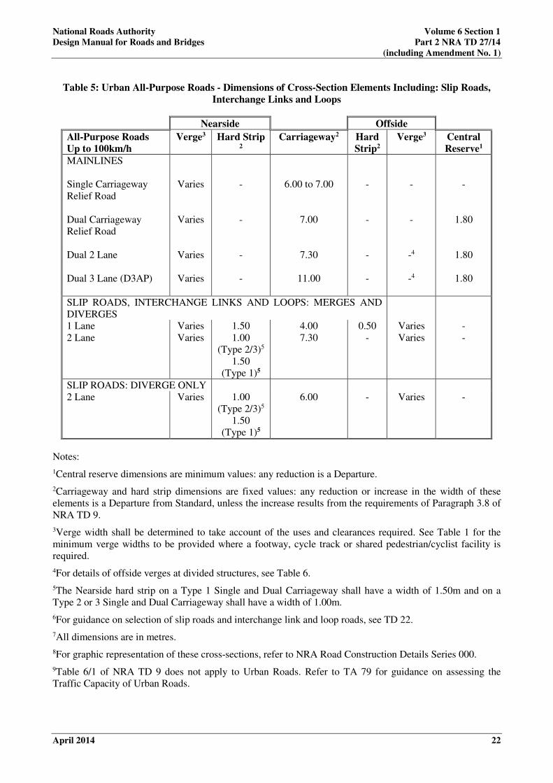
Table 5: Urban All-Purpose Roads - Dimensions of Cross-Section Elements Including: Slip Roads,
Interchange Links and Loops
Nearside Offside
All-Purpose Roads
Up to 100km/h
Verge3 Hard Strip 2
Carriageway2 Hard
Strip2
Verge3 Central
Reserve1
MAINLINES
Single Carriageway
Relief Road
Dual Carriageway
Relief Road
Dual 2 Lane
Dual 3 Lane (D3AP)
Varies
Varies
Varies
Varies
-
-
-
-
6.00 to 7.00
7.00
7.30
11.00
-
-
-
-
-
-
-4
-4
-
1.80
1.80
1.80
SLIP ROADS, INTERCHANGE LINKS AND LOOPS: MERGES AND
DIVERGES
1 Lane
2 Lane
Varies
Varies
1.50
1.00
(Type 2/3)5
1.50
(Type 1)5
4.00
7.30
0.50
-
Varies
Varies
-
-
SLIP ROADS: DIVERGE ONLY
2 Lane
Varies 1.00
(Type 2/3)5
1.50
(Type 1)5
6.00 - Varies -
Notes:
1Central reserve dimensions are minimum values: any reduction is a Departure.
2Carriageway and hard strip dimensions are fixed values: any reduction or increase in the width of these
elements is a Departure from Standard, unless the increase results from the requirements of Paragraph 3.8 of
NRA TD 9.
3Verge width shall be determined to take account of the uses and clearances required. See Table 1 for the
minimum verge widths to be provided where a footway, cycle track or shared pedestrian/cyclist facility is
required.
4For details of offside verges at divided structures, see Table 6.
5The Nearside hard strip on a Type 1 Single and Dual Carriageway shall have a width of 1.50m and on a
Type 2 or 3 Single and Dual Carriageway shall have a width of 1.00m.
6For guidance on selection of slip roads and interchange link and loop roads, see TD 22.
7All dimensions are in metres.
8For graphic representation of these cross-sections, refer to NRA Road Construction Details Series 000.
9Table 6/1 of NRA TD 9 does not apply to Urban Roads. Refer to TA 79 for guidance on assessing the
Traffic Capacity of Urban Roads.

National Roads Authority Volume 6 Section 1
Design Manual for Roads and Bridges Part 2 NRA TD 27/14
(including Amendment No. 1)
April 2014 23
4. CROSS-SECTIONS AT STRUCTURES
4.1 The cross-sections detailed below assume a straight horizontal alignment of the carriageway. If this
is not the case the verges and central reserve may require widening to give the stopping sight
distances required in accordance with NRA TD 9. For a graphic representation of the following
requirements, refer to NRA Road Construction Details Series 000 and NRA TD 300.
4.2 Variations of cross-section provision at bridges in close succession shall be avoided except where
sight distance requirements dictate otherwise. The verge and central reserve widths appropriate for
the longest structure shall be used. Individual cases shall be treated on their merits.
4.3 The requirements of this Standard are not applicable to road tunnels.
Roads diverted or improved on-line as part of a national road scheme
4.4 The cross-section at a structure of a road diverted or improved on-line as part of a national road
scheme shall have a minimum width of 5.5m.
Traffic Lane Widths
4.5 Lane widths shall be maintained through or over a structure.
Hard Shoulders and Hard Strips
4.6 Where hard shoulders or hard strips are provided adjacent to the edges of the carriageway they shall
be continued at the same width through or over the structure.
Central Reserves
4.7 The width of central reserve applicable to the adjacent open road section should be continued
through or over the structure.
Verges at Underbridges and Overbridges
4.8 In planning the overall width required, consideration should be given to the space necessary for
structural elements of the bridge, including: foundations, items such as bridge joints, drainage runs,
electrical equipment and services, and safety barriers. Consideration should also be given to
maintenance operation needs.
4.9 On all-purpose road overbridges, underbridges, elevated roads and viaducts, the nearside verge will
need to provide a clear width for pedestrian access and cycle facilities. The width can be varied
depending upon the overall length of the structure and the likely pedestrian and cyclist flows as
indicated in Paragraphs 4.11 to 4.16 and Table 6. Where it is anticipated that mobility impaired users
will be regular users of the structure, consideration shall be given to providing a width of 1.80m –
this allows for two wheelchair users to pass one another in opposite directions. Where regular use is
not envisaged, a minimum width of 1.5m is permissible, although passing places will be required at
regular intervals. An absolute minimum width of 2.75m shall be provided where cycle facilities are
to be provided in accordance with NRA TD300.

National Roads Authority Volume 6 Section 1
Design Manual for Roads and Bridges Part 2 NRA TD 27/14
(including Amendment No. 1)
April 2014 24
4.10 Regular pedestrian usage on an all-purpose road occurs where there is a clearly defined local need
with a predicted maximum flow of more than 25 pedestrians per hour and/or footways are provided,
or are to be provided, on contiguous sections of road. Occasional pedestrian usage occurs at other
locations.
4.11 Verge widths may need to be increased to allow adequate visibility, particularly where a bridge is
located on a horizontal curve.
Table 6: Verge Widths on Underbridges
Note: * For bridges carrying Regional and Local Roads it may be appropriate to treat one side as the offside
despite the road carrying two-way traffic.
Verges at Underbridges
4.12 On underbridges the verge adjacent to the bridge parapet shall be raised with a maximum kerb height
of 80mm. Kerbs shall be splayed for its full height, by at least 450 to the vertical. Any reduction in
width shall be regarded as a Departure.
Verges beneath Overbridges
4.13 Beneath overbridges the verge width shall be not less than 2.0m and shall also comply with the
following arrangements where applicable.
4.14 At overbridges where an abutment is adjacent to the carriageway:
a) The distance from the edge of road pavement to the face of the abutment shall be not less
than 4.50m.
b) Where there is regular pedestrian usage, a paved footway of 1.65m minimum clear width
shall be provided on the nearside verge behind any safety barrier. Consideration shall be
given to increasing this width to 1.80m where it is anticipated that there will be regular use
by mobility impaired users.
c) Where a cycle facility is to be provided an absolute minimum raised verge width of 2.75m
shall be provided. The cycle facility shall be located behind the safety barrier. See NRA
TD300 and RCD Series 000 for guidance on desirable minimum dimensions for cycle
facilities, lateral clearances and separation distances from the carriageway.
Road Type Location
Pedestrian/Cyclist
Usage
(see Paragraph 4.11)
Bridge Length
M
Raised Verge
Width
m
Motorway Nearside
Offside
-
-
All
All
0.60
0.60
All-Purpose Road Nearside
Regular
Regular
Occasional
Mobility Impaired Users
Rural Cycle Facilities
≤ 100
> 100
All
All
All
2.00
1.50
1.50
1.80
2.75 min
Offside* All All 0.60

National Roads Authority Volume 6 Section 1
Design Manual for Roads and Bridges Part 2 NRA TD 27/14
(including Amendment No. 1)
April 2014 25
4.15 At overbridges where a pier is adjacent to the carriageway:
a) The distance from the edge of the traffic lane to the face of the pier shall be not less than
4.5m.
b) The minimum distance from the edge of road pavement to the face of the pier shall be
determined to suit the safety barrier set-back and working width. Working width is the
distance from the traffic face of the safety barrier to the maximum dynamic deflected
position of the barrier after impact (see NRA TD 19).
c) There is regular pedestrian usage, a paved footway of 1.65m minimum clear width shall be
provided on the nearside through the span separate from the main carriageway.
Consideration shall be given to increase this width to 1.80m where it is anticipated that
there will be regular use by mobility impaired users.
d) Where a cycle facility is to be provided an absolute minimum raised verge width of 2.75m
shall be provided. The cycle facility shall be located behind the safety barrier. See NRA
TD300 and RCD Series 000 for guidance on desirable minimum dimensions for cycle
facilities, lateral clearances and separation distances from carriageway.
Safety Barriers and Bridge Parapets
4.16 Safety barriers and bridge parapets shall be positioned in accordance with the requirements of NRA
TD 19 and NRA BD 52.

National Roads Authority Volume 6 Section 1
Design Manual for Roads and Bridges Part 2 NRA TD 27/14
(including Amendment No. 1)
April 2014 26
5. HEADROOM AT STRUCTURES
General
5.1 Dimensional standards are given in Table 7 for “new construction headroom” and “maintained
headroom” at overbridges and at other structures over a road.
Table 7: Standard Headroom at Structures
Type of
Structure
New
Construction
Headroom
(m)
Maintained
Headroom
(m)
Overbridges 5.30 5.03
Footbridges
and
Sign/Signal
Gantries
5.70 5.41
Free Standing
Temporary
Structures
N/A 5.41
5.2 The headroom provision at underbridges shall be in accordance with Table 7 unless otherwise agreed
with the relevant Road, Railway or Water Authority.
5.3 The headroom values given are the minimum; where it is economical and/or environmentally
acceptable, greater headroom should be provided.
5.4 The requirements of this Standard are not applicable to road tunnels.
Dimensional Requirements
5.5 Headroom shall be measured at right-angles to the surfaces of the carriageway, hard shoulder, hard
strip, verge or central reserve, at the point where it is a minimum.
5.6 The relevant standard headroom in Table 7 shall be provided:
a) Over the paved carriageway, hard shoulder or hard strip plus any provision for future
widening;
b) Over the full verge width, except where (e) applies, and even then for a minimum of 4.5m
from the edge of the traffic lane;
c) Over the central reserve of a dual carriageway, except where (e) applies;
d) Between the carriageway and the pier or abutment face where such a support is located
within 4.5m of the edge of the road pavement, except where (e) applies;

National Roads Authority Volume 6 Section 1
Design Manual for Roads and Bridges Part 2 NRA TD 27/14
(including Amendment No. 1)
April 2014 27
e) Up to the back of the working width of a safety fence, when installed (see Figure 1). The
working width is the distance from the traffic face of the safety fence to the maximum
deflected position of the fence or vehicle after impact.
5.7 The headroom standards for pedestrian subways and combined pedestrian/cycle subways are
contained in TD 36. Guidance on the headroom requirement for equestrian usage is contained in TA
57. Headroom standards for rural cycle facilities are included in NRA TD 300.
Compensation for Vertical Sag Curvature and Deflection
5.8 Where the road passing underneath a structure is on a sag curve, the headroom values in Table 7
shall be increased in accordance with Table 8. The sag radius is measured along the carriageway
over a 25m chord.
Table 8: Sag Radius Compensation
Sag Radius (m) Additional Clearance
(mm)
<650
650
900
1000
1200
1500
2000
3000
6000
>6000
160
130
100
80
70
55
45
25
15
Nil
5.9 Allowances shall be made for the deflection of structures. The minimum headroom shall be
maintained for the serviceability limit state under the action of load combination 1 specified in the
current appropriate loading standard.
Utilities Companies’ and Other Authorities’ Apparatus
5.10 Greater headroom than that determined from Paragraphs 5.1 to 5.9 may be required by a Utility
Company or other authority. Any increase in the headroom dimension shall be agreed with the
National Roads Authority.

National Roads Authority Volume 6 Section 1
Design Manual for Roads and Bridges Part 2 NRA TD 27/14
(including Amendment No. 1)
April 2014 28
Figure 1: Headroom at Structures

National Roads Authority Volume 6 Section 1
Design Manual for Roads and Bridges Part 2 NRA TD 27/14
(including Amendment No. 1)
April 2014 29
6. REFERENCES
6.1 Design Manual for Roads and Bridges (DMRB):
a) NRA BD 2 (DMRB 1.1.1A) – Technical Approval of Structures on Motorways and Other
National Roads
b) BD 29 (DMRB 2.2.8) – Design Criteria for Footbridges.
c) NRA TD 19 (NRA DMRB 2.2.8A) – Safety Barriers.
d) NRA BD 52 (DMRB 2.3.3) – The Design of Highway Bridge Parapets.
e) NRA TD 9 (NRA DMRB 6.1.1) – Road Link Design.
f) NRA TD 10 (NRA DMRB 6.1.1B) – Road Link Design for Type 2 and Type 3 Dual
Carriageways.
g) TD 22 (DMRB 6.2.1) – Layout of Grade Separated Junctions.
h) TD 40 (DMRB 6.2.5) – Layout of Compact Grade Separated Junctions.
i) NRA TD 41-42 (DMRB 6.2.6) – Geometric Design of Major/Minor Priority Junctions and
Vehicular Access to National Roads.
j) TD 36 (DMRB 6.3.1) – Subways for Pedestrians and Pedal Cyclists. Layout and
Dimensions.
k) NRA TA 69 (DMRB 6.3.3) – The Location and Layout of Lay-bys.
l) TA 57 (DMRB 6.3) – Roadside Features.
m) HD 39 (DMRB 7.2.5) – Footway Design.
n) NRA TD 300 (DMRB 6.5.3) – Rural Cycle Scheme Design.
6.2 Other References
a) BS 6100-1 Building and Civil Engineering – Vocabulary – Part 1: General Items. British
Standards Institution, 389 Chiswick High Road, London W4 4AL.
b) BS 6100-4 Building and Civil Engineering – Vocabulary – Part 4: Transport. British
Standards Institution, 389 Chiswick High Road, London W4 4AL.
c) National Roads Project Management Guidelines. National Roads Authority.
d) NRA Manual of Contract Documents for Road Works Volume 2: Specification for
Roadworks. National Roads Authority.
e) NRA Manual of Contract Documents for Road Works Volume 4: Road Construction
Details. National Roads Authority.
f) Transport in the Urban Environment, Part V. The Institution of Highways and
Transportation.
g) Traffic Signs Manual. Department of Transport.
h) National Cycle Manual. National Transportation Authority.
National Roads Authority Volume 6 Section 1
Design Manual for Roads and Bridges Part 2 NRA TD 27/14
(including Amendment No. 1)
April 2014 30
7. ENQUIRIES
7.1 All technical enquiries or comments on this document, or any of the documents listed as forming part
of the NRA DMRB, should be sent by e-mail to [email protected], addressed to the following:
Head of Network Management, Engineering Standards & Research
National Roads Authority
St Martin’s House
Waterloo Road
Dublin 4
…………………………...
Pat Maher
Head of Network Management,
Engineering Standards & Research

National Roads Authority Volume 6 Section 1
Design Manual for Roads and Bridges Part 2 NRA TD 27/14
(including Amendment No. 1)
December 2014 i
National Roads Authority
Design Manual for Roads and Bridges
(NRA DMRB)
AMENDMENT No. 1 (December 2014) to
NRA TD 27 Cross-sections and Headroom, dated April 2014
NRA TD 27 Cross-sections and Headroom, dated April 2014 is amended as follows:-
1. Page 20, Table 3, Note 11
Insert the text ‘Verge width may be reduced to 3.00m for verges where provision of a cycle facility
has been omitted as per NRA TD 300’ at the end of the note.


Ionad Ghnó Gheata na
Páirce,
Stráid Gheata na Páirce, Baile Átha Cliath 8, Éire
www.tii.ie
+353 (01) 646 3600
Parkgate Business Centre,
Parkgate Street,
Dublin 8, Ireland
+353 (01) 646 3601