CROSS PASSAGES - Preene
6
Groundwater control and ground treatment CROSS PASSAGES INTERNATIONAL EDITION October 2020 The official magazine of the British Tunnelling Society
Transcript of CROSS PASSAGES - Preene

Groundwater control and ground treatment
CROSS PASSAGES
INTERNATIONAL EDITIONOctober 2020The offi cial magazine of the British Tunnelling Society
001tun1020_cover.indd 1 24/09/2020 09:58

14 | October 2020 | www.tunnelsandtunnelling.com
T E C H N I C A L / C R O S S P A S S A G E S
achieved by the construction of ‘cross passages’ which are spaced along the alignment.
In the most common geometry, each cross passage is aligned at right angles to the main tunnels (Figure 1) and is of smaller diameter. The spacing along the route is usually determined by regulatory requirements for emergency evacuation and fire-fighting, but spacings of 100 to 500m between cross passages are typical.
The constraint of modest diameter and short length means that cross passages are commonly constructed without the use of a TBM or shield. Excavation is typically by hand mining or mechanised excavation using small backactors or roadheaders
CROSS PASSAGES ARE A KEY part of many road and rail tunnelling schemes. Such projects use twin running
tunnels that are constructed parallel to each other. When the tunnels are in operation, safety requirements mean that there must be regular access connections to allow emergency evacuation from one running tunnel to another in the event of a fire or other hazardous event. The connection between running tunnels is
GROUNDWATER CONTROL FOR TUNNEL CROSS
PASSAGESDr Martin Preene of Preene Groundwater Consulting looks at the construction of cross
passages and the various techniques for groundwater control and ground treatment
Above: Figure 1, Schematic geometry of cross passage between running tunnels FROM CASHMAN & PREENE, 2020, WITH PERMISSION
014_018tun1020_preene.indd 14 24/09/2020 10:31

www.tunnelsandtunnelling.com | October 2020 | 15
C R O S S P A S S A G E S / T E C H N I C A L
cars or vehicles) to allow rapid movement into and out of the tunnel.
INVESTIGATION AND DATA GATHERINGThe lack of surface access often means that there is little pre-construction ground investigation information at cross passage locations and there can be significant uncertainty in ground and groundwater conditions. Various strategies can be used to gather further information including:i. Information from face interventions.
A strategy that is sometimes adopted is to plan face interventions during construction of the running tunnels to coincide with proposed cross passage locations. If the TBM support fluid is lowered to tunnel axis level (or lower) and compressed air applied to exclude groundwater, it can be possible to inspect the soil or rock at the face. This approach was adopted in the United Kingdom for the HS1 and the Crossrail projects.
ii. Probe drilling. Most cross passage works include provision for probe drilling out from the running tunnels at cross passage locations. The data gathered can include samples from the drilling flush or drilling tools, and information from the instrumented drilling equipment.
DRILLING OUT FROM TUNNELSDrilling out from tunnels is often difficult and inconvenient. If surface access
closely followed by the application of a primary lining of either sprayed concrete (SCL) or spheroidal graphite iron (SGI). Temporary support such as timber propping may be used before the primary lining is placed. These methods require stable conditions and manageable rates of groundwater inflow – effective groundwater control is therefore essential.
PRINCIPLES OF GROUNDWATER CONTROLGroundwater control for cross passages can be grouped into two categories:■ Ground treatment techniques used to exclude groundwater.
Typically, the ground treatment reduces permeability – examples include artificial ground freezing and various types of grouting. These methods can be applied vertically and inclined from ground level (if access allows) and sub-horizontally from within the tunnels.
■ Groundwater depressurisation by pumping. Pumping wells can be drilled from ground level (where access is available) or in-tunnel wells can be used, where small-diameter wells are drilled outwards from the tunnels.
Ground treatment and groundwater depressurisation for cross passages face two logistical challenges. Firstly, in most cases, surface access is not available above cross passage locations. Indeed, for sub-aqueous tunnels below rivers and open water, the ‘surface’ above a cross passage may be under many metres of water. Therefore, most work (drilling, ground treatment and pumping) must be done from within the tunnels.
This reveals the second problem, that the groundwater control works must be designed and scheduled to inconvenience other works as little as possible. If the running tunnels are still being driven, there is a need to feed materials to, and remove spoil from, the TBM, and in any case access may be needed to allow multiple cross passage works simultaneously. Fixed equipment such as in-tunnel pumps and freezeplants should be mounted so they do not block access along the running tunnels. Installation equipment, such as drilling rigs, must be mobile (on either rail
Above: Figure 2a, Typical drill hole arrays sub-parallel to cross passage for ground treatment and groundwater depressurisation FROM CASHMAN & PREENE, 2020, WITH PERMISSION
014_018tun1020_preene.indd 15 25/09/2020 14:07

16 | October 2020 | www.tunnelsandtunnelling.com
T E C H N I C A L / C R O S S P A S S A G E S
Common geometries of in-tunnel drill holes used for ground treatment and groundwater depressurisation are shown in Figure 2. The conical array of holes around the entire circumference of the cross passage (Figure 2a) is often used with ground treatment methods. The other geometries (Figures 2b and 2c) are often used for groundwater depressurisation systems where the soil/rock is sufficiently permeable to allow wells relatively distant from the cross passage to generate drawdowns over a wide area. In-tunnel drilling is typically carried out by specialist drilling rigs with sufficient articulation of the mast to allow drilling at various inclinations and locations within a tunnel.
DRILLING METHODSVarious drilling methods have been used successfully on cross-passage works. Roberts et al. (2015) ranked drilling methods in terms of the ability to control bore stability. 1. Auger drilling without a blow out preventer (BOP): this
method provides little bore control if pressurised sands or silts are encountered. However, it can be used in some low-permeability materials such as clay, where significant water inflow is not anticipated.
2. Rotary water/polymer flush drilling through a guillotine valve, without BOP: the drill string passes through the open valve. This allows the bore to be sealed with a valve as soon as the drill string is removed. This method is used when drilling in unweathered rock, where the risk of loss of ground is low, and the primary concern is high rates of water inflow if significant fractures are encountered.
3. Cased rotary water/polymer drilling through guillotine valve and BOP: this provides full control of the borehole annulus during drilling. Drilling is by a rotating casing fitted with a shoe bit.
4. As ‘3’ above, but with lost-bit drilling: a bit is attached to the end of the casing. When the hole is drilled to its final length, the well materials are installed. The bit is then detached by water pressure and the casing withdrawn, leaving the installation in place.
for drilling is available, it is preferable that as much ground treatment and groundwater depressurisation as possible is done from ground level. However, in most cases all of the ground treatment or depressurisation work will have to be done from within the running tunnels via holes drilled out through the lining.
Drilling patterns out from the tunnel will need to be planned to fit within the constraints of reinforcement and joints in the tunnel lining, as well as the temporary support around the cross passage openings. Drilling locations must also be selected to take account of existing in-tunnel infrastructure such as belt conveyors, ventilation ducts and utilities feeding the TBM.
Inflows through drill holesWhen drilling out through a tunnel lining into pressurised, saturated soil or weathered rock, there is a risk that the drill hole will allow inflow of water and soil/rock particles, leading to loss of ground and collapse of the drill hole before any liner can be installed. To avoid these problems, in many cases the drill hole is made through a ‘blow out preventer’ (BOP) connected to a steel standpipe attached and sealed into the tunnel lining.
Common BOP elements include: ■ A guillotine valve to seal the hole in the event of problems ■ A relief valve and tee piece to relieve high pressures and flows during
drilling ■ A ‘stuffing box’ or ‘preventer’ (which compresses flexible packing around
the rotating drilling rods/casing) to provide a seal and prevent excessive water passing into the tunnel around the rotating rods/casing.
Above: Figure 2b, Typical drill hole arrays radiating out from running tunnels for ground treatment and groundwater depressurisation FROM CASHMAN & PREENE, 2020, WITH PERMISSION
014_018tun1020_preene.indd 16 25/09/2020 14:08

www.tunnelsandtunnelling.com | October 2020 | 17
C R O S S P A S S A G E S / T E C H N I C A L
Experience indicates that maintaining bore control when drilling out from a tunnel becomes very difficult if pore water pressures are more than approximately 100kPa (10m head of water) above tunnel level.
GROUND TREATMENTGround treatment for cross passages can be used in two principal ways:■ To reduce the permeability of the soil or rock around the
cross passage to exclude groundwater from the works (any increase in strength of the treated soil/rock is of benefit, but is not the primary objective); and/or
■ To create a zone of strengthened soil or rock that can form a structural member increasing the stability of the excavation. This might be in the form of an arch or ‘hood’ of treated ground above the cross passage, or an inverted arch below it.
In-tunnel pumps are also required to deal with any residual seepage, including any water encountered immediately outside of the lining of the running tunnel when cross passage excavation commences.
Methods that have been successfully used in cross passage construction include permeation grouting and rock grouting; jet grouting; and artificial ground freezing.
Ground treatment by permeation or rock grouting is often undertaken via drill holes aligned sub-parallel to the cross passage with the objective of forming a complete block of treated ground. The grout type (OPC, microfine cements, chemical grouts) and injection method (stage grouting or tube-a-manchette) must be selected carefully to match the ground conditions. Typically, the grout holes are drilled and grouted in primary, secondary and tertiary patterns, with ‘water testing’ (a variation on packer permeability tests) employed periodically to assess the permeability reduction that has been achieved.
For ground treatment by artificial ground freezing, closely-spaced freezeholes are installed around the cross passage.
Above: Figure 3, Artificial ground freezing used in cross passage construction PHOTO COURTESY OF SOILFREEZE INC
Above: Figure 2c, Typical drill hole arrays with sub-vertical drill holes downward from the running tunnels for ground treatment and groundwater depressurisation FROM CASHMAN & PREENE, 2020, WITH PERMISSION
014_018tun1020_preene.indd 17 25/09/2020 14:08
18 | October 2020 | www.tunnelsandtunnelling.com
T E C H N I C A L / C R O S S P A S S A G E S
and reducing the time needed for active pumping to lower groundwater pressures.
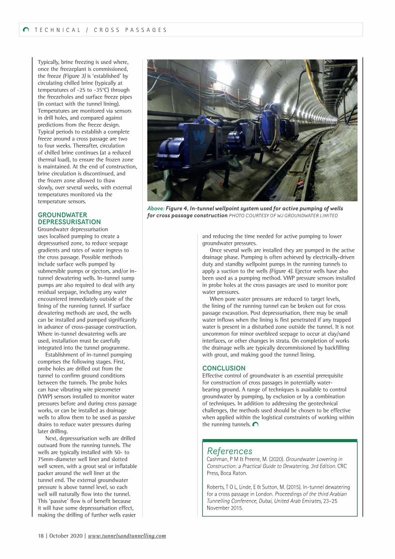
Once several wells are installed they are pumped in the active drainage phase. Pumping is often achieved by electrically-driven duty and standby wellpoint pumps in the running tunnels to apply a suction to the wells (Figure 4). Ejector wells have also been used as a pumping method. VWP pressure sensors installed in probe holes at the cross passages are used to monitor pore water pressures.
When pore water pressures are reduced to target levels, the lining of the running tunnel can be broken out for cross passage excavation. Post depressurisation, there may be small water inflows when the lining is first penetrated if any trapped water is present in a disturbed zone outside the tunnel. It is not uncommon for minor overbleed seepage to occur at clay/sand interfaces, or other changes in strata. On completion of works the drainage wells are typically decommissioned by backfilling with grout, and making good the tunnel lining.
CONCLUSIONEffective control of groundwater is an essential prerequisite for construction of cross passages in potentially water-bearing ground. A range of techniques is available to control groundwater by pumping, by exclusion or by a combination of techniques. In addition to addressing the geotechnical challenges, the methods used should be chosen to be effective when applied within the logistical constraints of working within the running tunnels.
Typically, brine freezing is used where, once the freezeplant is commissioned, the freeze (Figure 3) is ‘established’ by circulating chilled brine (typically at temperatures of -25 to -35°C) through the freezeholes and surface freeze pipes (in contact with the tunnel lining). Temperatures are monitored via sensors in drill holes, and compared against predictions from the freeze design. Typical periods to establish a complete freeze around a cross passage are two to four weeks. Thereafter, circulation of chilled brine continues (at a reduced thermal load), to ensure the frozen zone is maintained. At the end of construction, brine circulation is discontinued, and the frozen zone allowed to thaw slowly, over several weeks, with external temperatures monitored via the temperature sensors.
GROUNDWATER DEPRESSURISATIONGroundwater depressurisation uses localised pumping to create a depressurised zone, to reduce seepage gradients and rates of water ingress to the cross passage. Possible methods include surface wells pumped by submersible pumps or ejectors, and/or in-tunnel dewatering wells. In-tunnel sump pumps are also required to deal with any residual seepage, including any water encountered immediately outside of the lining of the running tunnel. If surface dewatering methods are used, the wells can be installed and pumped significantly in advance of cross-passage construction. Where in-tunnel dewatering wells are used, installation must be carefully integrated into the tunnel programme.
Establishment of in-tunnel pumping comprises the following stages. First, probe holes are drilled out from the tunnel to confirm ground conditions between the tunnels. The probe holes can have vibrating wire piezometer (VWP) sensors installed to monitor water pressures before and during cross passage works, or can be installed as drainage wells to allow them to be used as passive drains to reduce water pressures during later drilling.
Next, depressurisation wells are drilled outward from the running tunnels. The wells are typically installed with 50- to 75mm-diameter well liner and slotted well screen, with a grout seal or inflatable packer around the well liner at the tunnel end. The external groundwater pressure is above tunnel level, so each well will naturally flow into the tunnel. This ‘passive’ flow is of benefit because it will have some depressurisation effect, making the drilling of further wells easier
ReferencesCashman, P M & Preene, M. (2020). Groundwater Lowering in Construction: a Practical Guide to Dewatering, 3rd Edition. CRC Press, Boca Raton.
Roberts, T O L, Linde, E & Sutton, M. (2015). In-tunnel dewatering for a cross passage in London. Proceedings of the third Arabian Tunnelling Conference, Dubai, United Arab Emirates, 23–25 November 2015.
Above: Figure 4, In-tunnel wellpoint system used for active pumping of wells for cross passage construction PHOTO COURTESY OF WJ GROUNDWATER LIMITED
014_018tun1020_preene.indd 18 24/09/2020 10:34