Cross Connection Manual - City of Richmond
101
CITY OF RICHMOND, VIRGINIA DEPARTMENT OF PUBLIC UTILITIES CROSS CONNECTION CONTROL MANUAL March 2015
Transcript of Cross Connection Manual - City of Richmond

CITY OF RICHMOND, VIRGINIA
DEPARTMENT OF PUBLIC UTILITIES
CROSS CONNECTION CONTROL MANUAL
March 2015

Table of Contents Part Page # I. Introduction 3 II. Definitions 6 III. Elements of the Cross Connection Control and Backflow
Prevention Program 15
A. Basic Elements of the Program 16 B. Administration 16 C. Water Service Termination 17
D. Procedures/Degree of Hazard 17 E. Existing Connections Assessments 18 F. New or Modified Connections Assessments 20 G. Inspection Program 22 H. Testing and Maintenance of Devices 22 I. Backflow Prevention Device Tester 23 J. Records Maintenance Program 24
1. Listing of Customers 24 2. Listing of Customers with Devices 24 3. Questionnaires, Interviews and Test Reports 25 4. Device Overhaul or Replacement Reports 26
K. Reporting Contamination or Suspected Contamination 26 L. Thermal Expansion 27 M. Backflow Prevention Device Installer Qualifications 27 N. References 28
1 March 2015

IV. Required Installation 29 A. General 30 Table 4.1 – Types of Hazards 32 Table 4.2 – Determination of Degree of Hazard 34 B. Typical Backflow Prevention Device Installation 34 V. Fire Sprinkler System Requirements 36 A. Degree of Hazard 37
B. Plan Review and Approval 38 C. Design 38 VI. Standard Forms and Letters 40
• Notification and Violation Letters 41 • Backflow Assembly Test Report 46 • Backflow Prevention and Cross Connection
Control Inspection Report 47 • Cross Connection Control Questionnaire 48 • Site Assessment Survey Form 50
VII. Criteria for Approved Backflow Prevention Devices 52 A. Approved Devices 53
B. Device Specifications 53 VIII. Standard Drawings 60 IX. APPENDICES 85 Appendix A – Cross Connection Control and Backflow Prevention Ordinance and Code 86 Appendix B – References 88 Appendix C – VDH Cross Connection Regulations 90 Appendix D – Check List 97
Note: It is the responsibility of the reader or user of this document to ensure that the excerpts referenced within this manual are the latest or most up-to-date.
2 March 2015

PART I INTRODUCTION
3 March 2015

CROSS CONNECTION
CONTROL AND BACKFLOW PREVENTION
INTRODUCTION
According to the Virginia Department of Heath Waterworks Regulations (12 VAC 5-590-580), the City of Richmond must establish and enforce a program of cross connection control and backflow prevention to protect the City’s water distribution system, and to ensure that the system’s treated water is pure and safe for public consumption. Compliance with this requirement is a condition for the issuance and continued use of the Department’s Waterworks Operation Permit (to treat raw water and distribute potable drinking water). The purpose of the Cross Connection Control and Backflow Prevention Program (the Program) is to protect the City’s drinking water system from any cross connections made to or backflow entering the water distribution system and to protect the public health. The City of Richmond is responsible for providing potable water service to our customers in the City and surrounding municipalities. It is the City’s Department of Public Utilities (DPU) obligation to insure the health, safety and welfare of our customers by making a continuous effort to provide quality services. The focus of this document is to assure protection of water quality throughout the water distribution system and to our customers. DPU and the consumer have a shared responsibility for water quality. DPU’s responsibility is for the distribution system and water service up to and through the water meter. The consumer’s responsibility begins after the water meter and includes the service line and all the pipe, fittings and appliances beyond the meter. The City requires a service line backflow prevention device on each service line to facilities that have actual or potential uses other than domestic uses (cooking, drinking, bathing and toilet). DPU is responsible for determining when, where, and what type of backflow prevention must be installed on the service line, per the Waterworks Regulations (12 VAC 5-590-610). To maintain water quality, DPU must identify potential cross connections and determine necessary protection measures. To aid in this, the Cross Connection Control and Backflow Prevention Program was adopted in 1984. This version of the Program manual and regulations is a revision to the 2006 manual and regulations. The Program identifies those activities which pose a threat to the public potable (drinking) water supply through cross connections and backflow and sets forth appropriate protective measures. The purpose of the manual and regulations is to:
● Prevent backflow pollution or contamination of the water supply system by
requiring the installation of an appropriate backflow prevention device or by backflow prevention by separation at the service connection,
● Explain the criteria by which the City will determine the Degree of Hazard,
4 March 2015

● Define required backflow prevention assemblies or devices,
● Educate those who work with public water supplies, and ● Encourage consumers to actively support and implement cross connection
control for the purpose of protecting the public water supply. This manual is intended to address the requirements of the Water Purveyor (City of Richmond DPU) and the public water system. Additional requirements of the latest edition of the Plumbing Code must also be met.
If you have questions regarding the Cross Connection Control and Backflow Prevention Program, please contact the City’s Cross Connection Control Specialist at (804) 646-8544 or write to:
City of Richmond Department of Public Utilities Technical Services Division - Cross Connection Control 400 Jefferson Davis Highway Richmond, VA 23224
5 March 2015

PART II
DEFINITIONS
6 March 2015

CROSS CONNECTION
CONTROL AND BACKFLOW PREVENTION
DEFINITIONS
Air-Gap Separation
The term “Air-Gap Separation” shall mean the unobstructed physical separation through the free atmosphere between any pipe or faucet supplying water to a tank, plumbing fixture or other device. The physical separation shall be measured from the lowest opening of the pipe to the highest rim of the receptacle. An “approved air-gap separation” shall be a linear distance of at least two times the diameter of the supply pipe measured vertically above the rim of the vessel and the bottom of the discharge pipe. The minimum separation shall be two (2) inches in all cases.
ASSE
American Society of Sanitary Engineers
Atmospheric Vacuum Breaker
The term “Atmospheric vacuum breaker” (also known as the “non-pressure type vacuum breaker”) shall mean an assembly containing a float-check, a check to close the air inlet port. The flow of water into the body causes the float to close the air inlet port. When the flow of water stops the float falls and forms a check valve against backsiphonage and at the same time opens the air inlet port to allow air to enter and satisfy the vacuum. A shutoff immediately upstream may be an integral part of the assembly. An atmospheric vacuum breaker is designed to protect against a health hazard, (i.e. containment) under a backsiphonage condition only.
Auxiliary Water System
The term “auxiliary water system” shall mean any water system on or available to the premises other than the waterworks. These auxiliary water systems may include water from another purveyor’s waterworks or water from a source such as wells, lakes, or streams; or process fluids, or used water. They may be polluted or contaminated or objectionable, constitute a water source or system over which the water purveyor does not have control.
7 March 2015

Backflow
The term “backflow” shall mean the undesirable reversal of flow of water or mixtures of water and other liquids, gases or other substances into the distribution pipes of the potable supply of water from any source or sources.
Backflow Prevention Device – Approved
The term “backflow prevention device- approved” shall mean a device, method, or type of construction that has been investigated and approved by the Virginia Department of Health, Office of Drinking Water, Division of Water Supply Engineering for the effective prevention of backflow into a potable system. In addition, the appropriate American Society of Sanitary Engineers (ASSE) standard is as follows:
BOCA International Plumbing Code Table P-1505.11.1 - Air Gap Separation (A.G.) ASSE-1013 - Reduced Pressure Zone Backflow Preventer (RPZ) ASSE-1024 - Dual Check Valve Assembly Backflow Preventer (DCVA)
Backflow Prevention Device – Unapproved
The term “backflow prevention device-unapproved” shall mean an assembly that does not meet the requirements of the current ASSE standard and is therefore unacceptable for use in the City’s distribution system.
Backpressure
The term “backpressure” shall mean any elevation of pressure in the downstream piping system (by pump, elevation of piping, or steam and/or air pressure) above the supply pressure at the point of consideration which would cause, or tend to cause a reversal of the normal flow of potable water leading to backsiphonage.
Backsiphonage
The term “backsiphonage” shall mean a form of backflow where water from a consumer’s water service line (after the meter) is pulled back into the supply system due a decrease in water pressure in the supply system.
By-Pass
The term “by-pass” shall mean any piping arrangement, connection, removable section, swivel, changeable device or other temporary or permanent devices through which or because of which a backflow prevention device could be circumvented and a backflow could occur.
8 March 2015

CCCP
Cross Connection Control Program by the City of Richmond, Department of Public Utilities, Technical Services Division
CCCS
Cross Connection Control Specialist - an employee of the City of Richmond, Department of Public Utilities, Technical Services Division
Check Valve - Approved
The term “check valve- approved” shall mean a check valve that is drip tight in the normal direction of flow when the inlet pressure is at least one (1) psi and the outlet pressure is zero (0). The check valve shall permit no leakage in a direction reverse to the normal flow. The closure element (e.g. clapper, poppet or other design) shall be internally loaded to promote rapid and positive closure. An “approved check valve” is only one component of an approved backflow prevention device – i.e. pressure type, anti-siphon vacuum breaker, double check backflow prevention assembly, or reduced pressure backflow preventer.
Consumer
The term “consumer” shall mean the person who benefits from the water, wastewater, stormwater or gas service or any combination used or wasted on any premises within or without the corporate city limits, or means a customer.
Containment
The term “containment” shall mean that the appropriate type or method of backflow protection, commensurate with the degree of hazard of the consumer’s potable water system, is installed at the service connection. Therefore, any possible contamination of the water supply is contained within the consumer’s potable water system.
Contamination
The term “contamination” shall mean a degradation of the quality of the potable water by any solid, liquid, or gaseous compounds or mixtures which would create an actual or potential hazard to the public health, or would create an unacceptable, odor or color to potable water.
Customer
The term “customer” shall mean the person legally or equitably responsible for the payment of charges for stormwater, water, gas or wastewater service or any combination used or wasted on any premises within or without the corporate City limits.
9 March 2015

Critical Level
The term “critical level” shall mean the minimum elevation (height) above the rim of a fixture or receptacle at which a vacuum breaker device may be installed.
Cross Connection
The term “cross connection” shall mean any unprotected actual or potential connection or structural arrangement between a public or a consumer’s potable water system and any other source or system through which it is possible to induce into any part of the potable system any used water, industrial fluid, gas, or substance other than the intended potable water with which the system is supplied.
Degree of Hazard
The term “degree of hazard” is used to refer to the potential risk to health and adverse effect upon the waterworks.
Detector Check
The term “detector check” shall mean a fire line water meter consisting of a single check valve assembly and a by-pass water meter and a single check. The meter shall register accurately for low rates of flow and shall show a registration for all rates of flow.
Double Check Valve Backflow Prevention Assembly (DCVA)
The term “double check valve backflow prevention assembly” (DCVA) shall mean an assembly composed of two (2) independently acting, approved check valves, including tightly closing shut-off valves located at each end of the assembly and fitted with properly located test cocks. This assembly shall be a low hazard device to only be used to protect against a non-health hazard (i.e. pollutant).
Enclosure
The term “enclosure” shall refer to the above ground structure that encloses a backflow prevention device to prevent freezing. Enclosures shall conform to the requirements of ASSE 1060.
Facility
The term “facility” shall refer to something designed, built, or installed to afford a specific convenience or service.
10 March 2015

Health Agency
The term “Health Agency” shall mean the Virginia Department of Health, Office of Drinking Water, Division of Water Supply Engineering.
Health Hazard
The term “health hazard” shall mean an actual or potential threat of contamination of a physical or toxic nature to the public potable water system or the consumer’s potable water system to such a degree or intensity that there would be a danger to health.
Industrial Fluids
The term “industrial fluids” shall mean any liquid or solution which may be chemically, biologically or otherwise contaminated or polluted which would constitute a health, pollution or system hazard if introduced into the waterworks. This includes, but is not limited to:
• Polluted or contaminated water; • Process water; • Used waters, originating from the waterworks which may have deteriorated in sanitary
quality; • Cooling water; • Contaminated natural water taken from wells, lakes, streams, or irrigation systems, • Chemicals in solution or suspension; and • Oils, gases, acids, alkalis, and other liquid and gaseous fluid used in industrial or other
processes or fire fighting purposes. Inlet
The term “inlet” shall mean the open end of the water supply pipe through which the water is discharged into a plumbing fixture.
Main
The term “main” shall mean the pipe in a street extending parallel or nearly parallel to the line of property abutting thereon through which water is conveyed or distributed.
Multifamily
The term “multifamily” shall refer to housing where three or more separate housing units for residential (i.e. non-commercial) inhabitants are contained within one building or multiple buildings within one complex.
11 March 2015

Non-Health Hazard
The term “non-health hazard” shall mean an actual or potential threat to the physical properties of the public or consumer’s potable water system or of a contamination which would have a protracted effect on the quality of the potable water system. A non-health hazard is one that, if introduced into the public potable water supply system, would be a nuisance to the customer but would not adversely affect human health.
Point of Connection (POC)
The term “point of connection” shall mean the terminal end of a water pipe where water is delivered for use. Examples of “point of connections” are faucets and hose bibs.
Potable Water
The term “potable water” shall mean water from any source which has been permitted by the Virginia Department of Health and approved for human consumption.
Premises
The term “premises” shall mean land, building or other structure and appurtenances thereto, in addition to the separate units of any building or other structure and appurtenances thereto, which is served by a gas or water meter or both and which is assigned a unique account number by the department of public utilities.
Program
The term “program” shall mean the Cross Connection Control and Backflow Prevention Program of the City of Richmond. The program includes any rules and regulations of the DPU.
Reduced Pressure Zone Backflow Preventer (RPZ)
The term “reduced pressure zone backflow preventer” shjall mean a device containing a minimum of two (2) independently acting check valves together with an automatically operated pressure differential relief valve located between the two (2) check valves. During normal flow and at the cessation of normal flow, the pressure between these two (2) check valves shall be less than the supply pressure. In case of leakage of either check valve, the differential relief valve, by discharging to the atmosphere shall operate to maintain the pressure between the check valves at less than the supply pressure. The unit must include tightly closing shut-off valves located at each end of the device and each device shall be fitted with properly
12 March 2015

located test cocks. These devices must be the approved type. This device is designed to protect against a health hazard.
Service Connection
The term “service connection” shall mean the terminal end point of the public potable water system where the DPU loses jurisdiction and sanitary control over the water at its point of delivery to the consumer’s water system. The terminal end point is normally the water meter.
Service Line Protection
The term “service line protection” shall mean the appropriate type or method of backflow protection installed at the service connection, commensurate with the degree of hazard of the consumer’s potable water system.
Water Purveyor
The term “water purveyor” shall mean the City of Richmond Department of Public Utilities.
Water Service
The term “water service” shall mean the meter, facilities and equipment required to furnish water from the meter to the premises and the billing for services supplied through the meter to the consumer.
Water Service Connection
The term “water service connection” shall mean facilities and equipment in the street area between the water main and the property line used to supply water to any premises.
Water Supply
The term “water supply” shall mean any water that shall have been taken into waterworks from all wells, streams, springs, lakes and other bodies of water of surface waters (natural or impounded), and the tributaries thereto, and all impounded groundwater, but the term “water supply” shall not include any waters above the point of intake of such water works.
13 March 2015

Water Supply – Auxiliary
The term “water supply auxiliary” shall mean any water supply on or available to the premises other than the purveyor’s approved public potable water supply. These auxiliary water may include water from another purveyor’s public potable water supply or any natural source such as well, spring, river, stream, etc.
Water Supply – Unapproved
The term “water supply – unapproved” shall mean a water supply which has not been approved for human consumption by the Virginia Department of Health, Office of Drinking Water, Division of Water Supply Engineering.
Water System – Consumer’s Potable
The term “water system consumer’s potable” shall mean that portion of the privately owned water system lying between the point of delivery and point of use. This system will include all pipes conduits, tanks, receptacles, fixtures, equipment and appurtenances used to produce, convey, store or use potable water.
Water System – Public Potable
The term “water system Public potable” shall mean any public or privately owned water system operated as a public utility, under a valid health permit, to supply water for domestic purposes. This system will include all sources, facilities and appurtenances between the source and the point of delivery such as valves, pump, pipes, conduits, tanks, receptacles, fixtures, equipment and appurtenances used to produce, convey treat or store potable water for public consumption or use.
Waterworks
The term “waterworks” means a system that serves piped water for human consumption to at least 15 service connections or twenty-five (25) or more individuals for at least 60 days out of the year. "Waterworks” includes all structures, equipment and appurtenances used in the storage, collection, purification, treatment and distribution of pure water except the piping and fixtures inside the building where such water is_delivered.
Waterworks Owner
The term “waterworks owner” shall mean an individual, group of individuals, partnership, firm, association, institution, corporation, Municipal Corporation or the Federal Government which supplies water to any person within the State from or by means of any waterworks.
14 March 2015

PART III
ELEMENTS of the CROSS CONNECTION CONTROL
and
BACKFLOW PREVENTION
PROGRAM
15 March 2015

CROSS CONNECTION
CONTROL AND BACKFLOW PREVENTION
A. BASIC ELEMENTS of the PROGRAM
The purpose of the Cross Connection Control and Backflow Prevention Program is to protect the public water system. Basic elements of the Program include:
o Enforcing a service line protection program to protect the public water supply.
o Defining the personnel, equipment, supplies and organization to perform the
functions of the Program.
o Assessing the need for and type of required control measures for existing and proposed connections to the City’s water distribution system.
o Monitoring the Owner’s testing to determine the operational effectiveness of
devices installed on existing service connections to the City’s water distribution system.
o Maintaining records for the program: inspections, devices installed, tests
made, repairs made, non-compliant devices, etc.
o Reporting contamination or suspected contamination of the City’s water distribution system to the Department of Public Utilities and taking enforcement action as deemed necessary and allowed by City Code to ensure public safety.
o Monitoring devices previously found to be non-compliant with the
requirements of this Program and providing follow-up notification and enforcement action as deemed necessary and allowed by City Code to ensure public safety.
B. ADMINISTRATION
The City of Richmond, Department of Public Utilities, Technical Services Division - Cross Connection Control Specialist (CCCS) will be responsible for managing the City’s Cross Connection Control and Backflow Prevention Program (the Program).
The City has State of Virginia certified personnel who will be responsible for specific aspects of the Program.
16 March 2015

C. WATER SERVICE TERMINATION
As authorized by City Code Section 106-347, the Director of Public Utilities may terminate or prohibit, or otherwise control, water service to any Owner at a premises in the event the Director determines (i) that the Owner has failed to install any cross connection assembly, device or separation at the premises required pursuant to this Cross Connection Manual within a required deadline; (ii) that the Owner has failed to complete testing, inspection or overhauling of protection at the premises required pursuant to this Cross Connection Manual; (iii) that the Owner or the occupant of the premises otherwise has refused to comply with the requirements set forth in this Cross Connection Manual; or (iv) that such termination, prohibition, or abatement otherwise is necessary to protect the City’s water distribution system.
If the Director determines to terminate, prohibit, or otherwise control water service to an Owner, or otherwise to a premises, the Director shall issue the Owner and, if different than the Owner, the water service customer, a Notice of Violation setting forth such determination, including the reasons for the determination; the planned date of termination, prohibition, or control of water service if the water service is to be terminated or controlled, and the required remedial action to obtain, maintain, or restore water service.
D. PROCEDURES/DEGREE OF HAZARD
1. The Degree of Hazard is the potential risk from a cross connection or backflow to cause health and adverse effects upon the waterworks.
2. The BOCA International Plumbing Code only recognizes backflow
prevention devices for either “high” or “low” Degrees of Hazard. For “high” Degree of Hazard connections a reduced pressure zone (RPZ) backflow preventer is required. For “low” Degree of Hazard connections a double check valve assembly (DCVA) backflow preventer is required.
3. Since the City of Richmond DPU does not inspect test, or maintain
point of connection (POC) backflow devices, the City assumes that at least one (1) POC device is malfunctioning. Therefore, all connections within the City are “high” Degree of Hazard connections with only two (2) exceptions to this assumption:
o The City allows the use of DCVA backflow preventers on
“low” Degree of Hazard fire service connections which are a fire service with only a Siamese connection.
17 March 2015

o The City does not require the use of backflow prevention devices on single family residential connections and residential duplexes that have only domestic use services (cooking, drinking, bathing and toilet). Residences that have pools, hot tubs, irrigation systems, fire systems, or other cross connections that are determined to be “high hazard” by the Director of Public Utilities, require RPZ backflow preventers. (Table 2.10 in Appendix C of this manual is a guide to determine the degree of hazard for any situation.) Residences that operate a business or have a private well are also required to have RPZ backflow preventers.
E. EXISTING CONNECTIONS ASSESSMENTS
Assessments may be performed by questionnaire, interviews or on-site assessments. Interviews may be conducted on-site or by telephone at the discretion of the CCCS.
1. Assessments by Questionnaire
o Annual questionnaires may be sent to each Customer.
o The results of the annual questionnaires will be reviewed by the CCCS. Based on the response to the questionnaires, cross connection control interviews will be scheduled and appropriate backflow prevention devices required to provide containment determined. No response to the questionnaire will prompt an on-site interview. Refusal of access for inspection or provision of pertinent information shall prompt the requirement to install a high hazard containment device. A high hazard device is required on all service containment except fire sprinkling which may require both.
2. Assessment By Interview
o Interviews will follow a prepared questionnaire to assess the
need for cross connection control by containment.
o Available information about the premises to be surveyed will be gathered prior to the interview.
o The reasons for cross connection control and backflow
prevention as well as the degree of hazard determined will be explained to the customer or the customer’s representative.
18 March 2015

o The questionnaire will cover the following topics:
• Water uses after water enters the premises. • The current use of the facility. • Plans for future expansion and possible additional abatement. • Plans for any change in the use of the facility. • A list of all fixtures on the premises. • A list of all equipment used on the premises. • A list of any chemicals used on the premises. • Existing backflow prevention devices.
o All information will be recorded on the prepared questionnaire.
o Based on the information on the questionnaire an assessment of the Degrees of Hazard for the premises will be made.
o The results of the Interview, with the Degrees of Hazard
assessment and recommendations for containment or isolation devices, will be submitted to the Department of Public Utilities Technical Services Division - Cross Connection Control Specialist (CCCS).
3. On-Site Assessments
o Based on the results of the questionnaire and/or the interview,
an on-site inspection of the premises may be required. Facilities defined in Part IV, Paragraph A will automatically require an on-site assessment and control device or air gap.
o Any Owner or Owner’s representative that does not allow an on-
site assessment shall be guilty of a misdemeanor pursuant to City Code Section 106-2 and shall be subject to a fine. Each refusal of an on-site assessment shall be a separate offense.
o On-Site assessments shall be made by personnel of the
Technical Services Division - Cross Connection Control.
4. Customer Notification
o The CCCS will notify the Customer in writing as to the required location of any assembly or device; type of assembly or device, including applicable American Society of Sanitary Engineering (ASSE) standards; installation requirements; and the deadline for completing the installation (usually 30 days and in accordance with the manufacturer’s requirements).
19 March 2015

o If the Customer is not the Owner, meaning the person who has legal or equitable title to the premises, the Owner shall be notified by the CCCS in writing of the required location of any assembly or device; type of assembly or device, including applicable American Society of Sanitary Engineering (ASSE) standards; installation requirements; and the deadline for completing the installation, usually 30 days, and installed in accordance with the manufacturer’s requirements.
o If the Owner fails to install any required assembly, device or
separation within the deadline or fails to complete testing, inspection or overhauling as required, a Notice of Violation may be prepared in accordance with City Code Sections 106-313 & 106-347 and may include a notification of termination of water service as allowed by City Code Section 106-250 unless the compliance is obtained within a satisfactory timeframe as established by DPU.
F. NEW OR MODIFIED CONNECTIONS ASSESSMENTS
1. New Premises
o All new use or modified use applications shall be reviewed by
the CCCS for cross connection control requirements prior to issuance of a building permit.
• The location of any backflow prevention device shall be
shown on the site plan.
• Existing plumbing from the building to the connection and/or water meter must be shown. Proposed plumbing from the building to the water connection must also be shown.
• When the site plan reflects the installation of a
backflow prevention device, such devices shall be of the approved type, tested by a recognized testing laboratory or agency, approved by the CCCS. The criteria for approved backflow prevention devices are included in Part VII of this document.
• Detailed drawings of the backflow prevention device
installation shall be submitted for review. Submitted detailed drawings shall include: type, manufacturer, model, size, clearance from wall, distance to floor or pad, distance to ceiling, distance from walls, isolation valves, pad, enclosure and distance to drains.
20 March 2015

• The CCCS shall review the plans and advise whether they are approved or disapproved. Disapproved site plans shall be revised and resubmitted for additional review.
• If a fire system is proposed, show proposed connection
to the City’s main, the proposed City meter vault location and the location of the backflow prevention device (including type of device, clearances and type of freeze proof enclosure where applicable).
• If an underground irrigation system is proposed, the site
plan must show the proposed water line tie-in and the proposed location of an approved backflow prevention device at the service connection.
o If changes are made to the water system during construction,
modified plans shall be submitted to the CCCS for review. Disapproved plans shall be revised and resubmitted for additional review. The meter will be withheld until the modified plans are approved.
o Required assemblies, devices or separations shall be operational
prior to issuance of a Certificate of Occupancy. The initial testing of the devices will be performed by a state certified backflow prevention device tester at the Customer’s expense. The results of the test shall be submitted to the CCCS. If the backflow assembly fails inspection or testing, the meter will be withheld until backflow assembly is approved or passes testing.
o A follow up inspection of all premises, except residential, may
be performed by the CCCS within 30 days of occupancy.
o The Building Inspection Department will coordinate cross connection control requirements at new construction, properties where building usage has changed, properties where booster or fire pumps are used and all other incidences where plumbing modifications occur with the CCCS.
2. Existing Premises with Modified Water Supplies
o Existing premises requesting a new service connection or
reconnection to the waterworks (modified service) must be assessed by an on-site interview for cross connection hazards
21 March 2015

and the appropriate device installed, inspected and operational prior to making the service connection.
• The owner shall submit plans for the new service
connection in accordance with Section 1.
o Existing premises with individual water supplies (i.e. an auxiliary water system) may, upon approval of the DPU, maintain the water supply on the premises if a separation from the consumer’s water supply system is provided and maintained and access is granted for inspections. A written request must be made and the City Building Official must concur.
G. INSPECTION PROGRAM
1. The CCCS shall inspect and approve service line protection when
required to ensure protection measures, including installation location, have been taken.
2. CCCS inspections will be scheduled in priority according to known
Degree of Hazard associated with the consumer being served. Services with a “high” Degree of Hazard will be surveyed first. Others shall come in order.
3. Residential customers shall be informed of potential cross
connections in and around the home through educational brochures and other information sent periodically in conjunction with the billing cycle.
4. Annual assessments by questionnaires shall be conducted and results
filed or acted upon as appropriate.
H. TESTING and MAINTENANCE of BACKFLOW PREVENTION DEVICES
1. The Customer shall ensure that all backflow prevention devices shall be
inspected and tested annually by a state certified backflow prevention device tester at the Customer’s expense. The results of the testing shall be submitted to the CCCS.
2. Testing procedure shall be in accordance with the manufacturer’s
instructions and approved by the CCCS.
3. Backflow prevention devices that fail inspection or testing, or both, shall be overhauled or replaced at the Customer’s expense. The service connection will be closed, or a tested temporary backflow prevention
22 March 2015
device installed, until the failed backflow prevention device has been overhauled or replaced. After overhauling, the backflow prevention device shall be tested.
4. Backflow prevention device overhaul intervals shall not exceed the
manufacturer’s recommendation. If the overhaul interval has been exceeded the backflow prevention device will be considered failed.
5. Test reports shall be submitted to the CCCS. The CCCS will review
and track the testing reports.
6. Customer shall replace containment devices as recommended by the manufacturer.
I. BACKFLOW PREVENTION DEVICE TESTER
1. The backflow prevention device tester is responsible for making competent inspections and for repairing or overhauling backflow prevention assemblies, devices and making reports of such repairs to the consumer’s water supply owner on forms approved by the DPU. The backflow prevention device tester must be state certified.
2. A backflow prevention device tester shall be certified by the Virginia
Department of Professional and Occupational Regulation (DPOR) and shall have an active status. The backflow prevention device tester shall maintain their certification per the rules and regulations of the DPOR.
3. The tester shall include the list of materials or replacement parts used
and insure that parts used in the repair of the backflow prevention assembly or device meet the manufacturer’s recommendations.
4. The tester shall not change the design or operational characteristics of an
assembly or device or separation during repair or maintenance without prior written approval of the water service owner and the DPU.
5. The tester shall be equipped with and be competent in the use of all the
necessary tools, gauges, manometers and other equipment necessary to properly test, repair and maintain backflow prevention assemblies and devices.
6. Cost for testing and repair of backflow prevention devices shall be paid
for by the owner.
23 March 2015

J. RECORDS MAINTENANCE PROGRAM
1. An up-to-date listing of all Customers shall be maintained by the CCCS. The list will contain:
o Customer of premises o Tenant o Name of premises o Service address o Phone Number o Contact person o Number of service connections o Size of service connection o Annual Testing Report
2. An up-to-date listing of Customers who have cross connection control assemblies and devices (including pressure sensing devices) or separations (including separations from auxiliary or non-potable water systems and air gaps) installed shall be maintained by the CCCS. The list will contain:
o Customer of premises o Tenant o Name of premises o Service address o Phone Number o Contact person o Locations of assemblies, devices or separations o Device manufacturer o Device model number o Device serial number o Device size o Device ASSE number o Cross Connection or pressure sensing device tested annually o Pressure sensing device manufacturer o Pressure sensing device model number o Pressure sensing device serial number o Pressure sensing device pressure set point o Type of separation
• air gap • physical disconnection
o Separation verified annually
24 March 2015

o Type of protection
• Service line containment device
o Access for inspection (granted) (denied) (not necessary)
3. Questionnaires, cross connection control interview reports and testing reports shall be maintained by the CCCS for ten (10) years. The reports will contain:
o Listings as noted in Paragraph J, Sections 1 & 2.
o An assessment of:
• Degree of Hazard • Appropriateness of assembly, device or separation • Installation acceptable • General condition of assembly, device or separation • Repair / replacement recommendations • New / additional abatement or control recommendations • Any indication of thermal expansion problems
o Site Assessment Survey form (see Part VI) o Line pressure o Results of testing o Test method used o Date, license number and signature of device tester o Master plumber license number and signature of device installer o If repairs were made, the test report will contain:
• Which parts replaced • Replacements parts used • Probable cause of test failure • Preventative measures taken
o Backflow Assembly Test Report form (see Part VI) o Brief explanation of causes of backflow and control measures.
These causes may include, but will not be limited to:
• Spring, hot tub, cistern or swimming pool connected to the house plumbing system
• Water softeners improperly connected • Individual wells, springs or cisterns on the property • Pressure booster pumps • Water storage tanks • Water treatment systems
25 March 2015

• Outside hose bibs used in conjunction with:
Chemical sprayers Jet spray washers Swimming pools, hot tubs, saunas, etc. Lawn sprinkler or irrigation systems
• Photographic developing • Utility sinks with hoses extending below the sink rim • Animal watering troughs
o Existing cross connection control assemblies, devices or separations:
• Working properly • Leaking, noisy • Any modifications or repairs made • Date of last test • Any problems with hot water tank relief valve or faucet
washers not lasting very long
o Also included with the questionnaire should be:
• Educational material • Who to contact for additional information • Who to contact if contamination is ever suspected • A deadline to respond to the questionnaire
o See Part VI for the Questionnaire Forms (residential) (Commercial)
4. Residential containment double check valve assembly device (ASSE #1024)
overhaul or replacement reports shall be maintained by the CCCS for ten (10) years. The report will contain:
o Listings as noted in Paragraph J, Sections 1 & 2. o Overhaul/replacement action o Date of action
K. REPORTING CONTAMINATION or SUSPECTED CONTAMINATION
1. The water supply system owner, Local Building Official, device tester or any other person shall immediately report contamination or the suspicion of contamination to DPU at the following number as well as all other applicable City or State offices and departments:
o DPU General – (804) 646-7000 or 311; DPU Cross Connection – (804) 646-8510
26 March 2015

o Virginia Department of Health, Office of Drinking Water, East Central Field Office [ECFO], telephone – (804) 674-2880
o Local Health Department, Environmental Health Divisions (804) 205-3912
2. The City’s Cross Connection Control Specialist [CCCS] supervises daily
operations of cross connections staff and monitors, evaluates, and generates operational policies and procedures. This position also explains, reviews, and enforces codes, laws and ordinances governing potable water distribution systems, investigates complaints and conducts inspections, prepares reports, issues violation notices, prepares related correspondence and inspects establishments to verify compliance with City codes for cross connection control and water backflow prevention.
3. The City of Richmond Water Plant, with assistance from the CCCS, will be
responsible for investigating reports of contamination or suspected contamination and will be responsible for notifying the appropriate Virginia Department of Health, Office of Drinking Water, ECFO. A written report will be submitted by the 10th day of the month following the month during which backflow occurred addressing the incident, its causes, affects and preventative or control measures taken.
L. THERMAL EXPANSION
Customers should be advised (by the Plumbing Inspector) of the potential for thermal expansion prior to or during installation of a backflow prevention device. Solutions to thermal expansion will be at the discretion of the water supply system owner and at the expense of the water supply system owner.
M. BACKFLOW PREVENTION DEVICE INSTALLER QUALIFICATIONS
1. If the contract amount is over $1,000, backflow prevention devices shall be installed by a licensed plumbing contractor. If the contract amount is under $1,000, backflow prevention devices may be installed by a State licensed Master Plumber. Backflow prevention devices installed as part of a fire sprinkler system may be installed by an employee of a licensed fire sprinkler contractor who holds a National Institute for Certification in Engineering Technologies (NICET) Level 3 certification.
2. A plumbing permit issued through the City’s Bureau of Permits must be obtained to install a backflow device.
27 March 2015

N. REFERENCES – Latest Edition of Each Shall Apply
1. Virginia Cross Connection Control Association – Recommended Best Practice
2. The latest edition of the Code as approved by the City of Richmond
3. EPA Cross Connection Control Manual
4. Virginia Waterworks Regulations
5. The American Society of Sanitary Engineers (ASSE) shall be the governing testing agency.
6. Installation guidelines published by the manufacturer of the backflow
device being installed.
7. AWWA M14 – Recommended Practice for Backflow Prevention and Cross Connection Control.
8. BOCA International Plumbing Code
28 March 2015

PART IV
REQUIRED INSTALLATION
29 March 2015

CROSS CONNECTION CONTROL AND
BACKFLOW PREVENTION
INSTALLATIONS REQUIRING BACKFLOW PREVENTION DEVICES
A. GENERAL
An approved backflow prevention device, that complies with the Uniform Statewide Building Code, shall be installed in accordance with applicable references on each service connection to a consumer’s water system serving, but not necessarily limited to, the following types of facilities:
1. Hospitals, mortuaries, clinics, veterinary clinics, nursing homes, medical buildings and laboratories
2. Restaurants
3. Piers, docks, and water front facilities
4. Sewage treatment plants, sewage and storm water pumping stations
5. Food, beverage processing plants
6. Chemical plants, dyeing plants and pharmaceutical plants
7. Metal processing industries
8. Petroleum or natural gas processing or storage plants
9. Radioactive materials processing plants or nuclear reactors
10. Car washes and laundries
11. Lawn sprinkler and/or irrigation systems
12. Fire service systems
13. Slaughter or poultry processing plants
14. Farms where water is used for other tan household purposes
15. Commercial greenhouses and Nurseries
30 March 2015

16. Health clubs with swimming pools, therapeutic baths, hot tubs or saunas
17. Paper products plants and printing plants
18. Pesticide or exterminating companies and their vehicles with storage or mixing tanks
19. Schools or colleges
20. High-rise buildings (4 or more stories)
21. Multi-use commercial, office or warehouse facilities
22. Other specified by the Director of Public Utilities where
reasonable cause can be shown for a potential cross connection or backflow hazard
In addition, cross connection control devices will be required in each of the following situations:
o Premises having complicated plumbing or restrictive security which make it impractical to determine whether or not a cross connection exists.
o Premises with a history of cross connections being established or reestablished. o Premises having fire protection systems utilizing a combination of sprinklers, fire
loops, storage tanks, pumps, antifreeze protection, or auxiliary water sources including Siamese connections.
o Other premises specified by the division or the purveyor where cause can be shown that a potential cross connection hazard not listed above exists.
31 March 2015

TABLE 4.1
CROSS CONNECTIONS, HAZARDS FOUND, RECOMMENDED TYPE OF
PROTECTION
Facility Hazards Found Type of Protection
A. Hospitals, Mortuaries, clinics,
veterinary clinics, nursing homes, medical buildings, laboratories
Bedpan washers, flush valve toilets, autoclaves, specimen tanks, aspirators, lab equipment, autopsy and mortuary equipment, etc.
Air gap separation or RPZ backflow device on the service connection
B. Restaurants Cookers, tanks, cleaning chemicals and equipment, etc.
Air gap separation or RPZ backflow device on the service connection
C. Piers, docks, waterfront buildings
Auxiliary water, raw water connections, steam boilers, mud pumps, oil and gas tanks, reservoirs, etc.
Air gap separation or RPZ backflow device on the service connection
D. Sewage treatment plants, Sewage and storm water Pumping stations
Sewage pumps, sewage sump ejectors, laboratories, chemical storage, etc.
Air gap separation or RPZ backflow device on the service connection
E. Food, beverage processing plants
Cookers, autoclaves, tanks, fill lines, steam connected facilities, chemicals, cleaning equipment, etc.
Air gap separation or RPZ backflow device on the service connection. Double check device when there is a pollution hazard only
F. Chemical plants, dyeing plants pharmaceutical plants
Chemical tanks, vessels, fill lines, industrial fluid lines, storage reservoirs, fire foam equipment, etc
Air gap separation or RPZ backflow device on the service connection
G. Metal plating industries Industrial fluid lines, metals in solutions, cyanic, cleaning equipment, tanks, vessels, reservoirs, etc.
Air gap separation or RPZ backflow device on the service connection
H. Petroleum, natural gas processing or storage plants
Steam boilers, mud pumps, tanks vessels, industrial fluid lines, fire foam equipment, etc.
Air gap separation or RPZ backflow device on the service connection
32 March 2015

TABLE 4.1 (cont.)
CROSS CONNECTIONS, HAZARDS FOUND, RECOMMENDED TYPE OF PROTECTION
Facility Hazard Found Type of Protection
I. Radioactive materials processing plants or nuclear reactors
Chemical tanks, autoclaves, cleaning equipment, fire foam equipment, chemicals, metals in solution, etc.
Air gap separation or RPZ backflow device on the service connection
J. Car washes and commercial laundries
Soap, wax aspirating equipment, reclaimed water lines, fill and feed lines, etc.
Air gap separation or RPZ backflow device on the service connection
K. Lawn sprinkler systems Submerged outlets, chemicals, pumps, stagnant or polluted ground water, etc.
An RPZ device on lines that are connected with chemicals. A PVB device on wet systems must be 1’ above highest head.
L. Fire service systems Sprinkler systems, foam systems, tank, auxiliary water, anti-freeze, chemicals, pumps, pumper connection, etc.
Air gap separation or RPZ backflow device on the service connection
M. Slaughter or poultry processing plants
Industrial fluid lines, cleaning, bleaching, chemicals, wastes, etc
Air gap separation or RPZ backflow device on the service connection
N. Farms where water is used for other than household purposes
Chemical fertilizer, biological Contaminants, storage tanks, pumps, etc,
Air gap separation or RPZ backflow device on the service connection
O. Commercial greenhouses Chemical fertilizer, aspirating equipment, sprinkler lines, tanks, vessels, pumps, etc,
Air gap separation or RPZ backflow device on the service connection
P. Health clubs with swimming pools, therapeutic baths, hot tubs or saunas
Chemicals, pumps, flush valve toilets, cooling towers, soap, fill lines, steam boilers, etc.
Air gap separation or RPZ backflow device on the service connection
S. Schools and colleges Biological labs, flush valve toilets, specimen tanks, reservoirs, cooling towers, autopsy and morgue equipment, etc.
Air gap separation or RPZ backflow device on the service connection
T. High-rise buildings (4 or more stories)
Multiple services, change of Occupancy, flush valve toilets, pumps, cooling towers, steam boilers, etc.
Air gap separation or RPZ backflow device on the service connection
U. Multi-use commercial, office Multiple services, change of occupancy, internal looping of lines, industrial fluid lines, etc
Air gap separation or RPZ backflow device on the service connection
33 March 2015

TABLE 4.2
DETERMINATION OF DEGREE OF HAZARD
B. TYPICAL BACKFLOW PREVENTION DEVICE INSTALLATION
Once a Degree of Hazard has been determined and properly classified, remedial steps shall be taken to correct the condition or an approved backflow prevention device shall be installed.
1. The criteria for approved backflow prevention devices can be found in Part VII.
2. The DPU will be responsible for determining which type backflow prevention
device is required. The Customer shall be responsible for installing the backflow prevention device in accordance with the manual and ordinance.
3. Installations shall be in accordance with the drawing details in Part VIII.
4. An air gap separation or an approved Reduced Pressure Zone (RPZ)
backflow prevention device shall be installed where contamination hazards are found or where the potential exists. Examples of such facilities would be those facilities listed in Table 4.1.
NOTE: air gap separation and reduced pressure principle backflow prevention device will protect against backpressure, but vacuum breakers will not. Air gaps give the highest degree of protection and shall be used whenever practical to do so in high hazard situations subject to back pressure.
34 March 2015

5. An approved Double Check Valve Assembly (DCVA) backflow prevention device may be installed where the Degree of Hazard is low. In the City of Richmond, the only application is a fire suppression system. Fire suppression systems that are “high hazard” shall have an RPZ backflow prevention device installed. For detailed information on “high hazard” fire suppression systems see Part V – Fire Sprinkler System Requirements.
6. RPZ backflow prevention devices shall also be installed on lawn/irrigation sprinkler
systems. If the sprinkler system has a booster pump, a low pressure regulator or cut-off device shall be installed to prevent the inlet pressure from dropping below 10 psi [12 VAC 5-590-610(d)].
7. Trucks using portable hydrant meters shall be equipped with an approved air gap or
provide an approved RPZ backflow prevention device on the fill line. See Drawing TANKTRK in Part VIII.
8. Barometric loops are not an acceptable cross connection control device.
9. No devices shall be installed in pits except as specifically approved by the DPU in
cases of unique circumstances.
10. If the contract amount is over $1,000, backflow prevention devices shall be installed by a licensed plumbing contractor. If the contract amount is under $1,000, backflow prevention devices may be installed by a State licensed Master Plumber. Backflow prevention devices installed as part of a fire sprinkler system may be installed by an employee of a licensed fire sprinkler contractor who holds a National Institute for Certification in Engineering Technologies (NICET) Level 3 certification.
11. High rise buildings (4 or more stories) with an in-line system booster pump shall have
a low pressure regulator or cut-off device shall be installed to prevent the inlet pressure from dropping below 10 psi [12 VAC 5-590-610(d)].
35 March 2015

PART V
FIRE SPRINKLER SYSTEM REQUIREMENTS
36 March 2015

CROSS CONNECTION CONTROL
AND BACKFLOW PREVENTION
FIRE SPRINKLER SYSTEM REQUIREMENTS
A. DEGREE OF HAZARD
1. Fire Sprinkler Systems, because of their varying Degree of Hazard, must be evaluated by the Department of Public Utilities, Technical Services Division – Cross Connection Control Specialist (CCCS). All fire sprinkler systems shall have a detector check meter and a backflow preventer as set forth in Sections 2 & 3.
2. Low Degree of Hazard fire sprinkler system services will be equipped with a City
approved detector check meter and Double Check Valve Assembly (DCVA) to assure protection of the City water supply from contamination. The DCVA will be installed in an approved vault as near to the property line as possible (See Standard Drawings FIRE-A and LO-HAZ). Maintenance responsibility of the Department of Public Utilities (DPU) will end immediately preceding the inlet gate valve of the assembly.
Example of a “low” Degree of Hazard fire service connection are:
o A standard Siamese fire department connection. o A plain dry riser system. o A wet system without additives or compressed air.
3. High Degree of Hazard fire sprinkler system services will be equipped with a City
approved detector check meter and Reduced Pressure Zone (RPZ) backflow preventer. A “high” Degree of Hazard fire service connection is:
o A system with pumper connections where corrosion inhibitors or other
chemicals are added, o All foamite plant installations, o A system where an unapproved water supply is permanently connected to a
fire hydrant, o A system in which antifreeze is used, o Auxiliary water supplies, o A system with storage tanks, o A “dry” system with compressed air. o Complex fire systems where the City cannot verify the installation. o Existing systems where the City cannot verify the installation. o A service connection that combines the domestic and fire services into a
single pipe.
37 March 2015

4. The RPZ backflow preventer will be installed as near to the property line as possible (See Standard Drawings FIRE-A and HI-HAZ). Maintenance responsibility of DPU will end immediately preceding the inlet gate valve of the assembly.
B. PLAN REVIEW AND APPROVAL
1. The CCCS will perform plan review of the proposed water line extension up to the first approved gate valve located on the inlet side of the DCVA and the plan review of the assembly as it relates to the backflow device, etc. For fire service laterals, a gate valve shall be installed on the tee at the main. In all cases the engineer shall provide details illustrating what type of anchoring will be used on the inlet side of the assembly, so that the approved valve (inlet side) of the DCVA will not blow off when the DCVA is removed.
2. The CCCS will review the plan for the location of the backflow prevention device at such
time as a utilities plan is submitted to DPU. Separate plans for the location of the backflow prevention device shall be submitted to the CCCS.
3. An auxiliary mechanical permit issued by the Building Inspector’s Office, along with four
(4) sets of plans, is required for the work from the vault to the building and shall be applied for by the installing contractor from the Building Inspector’s Office and plans submitted to and reviewed by the Fire Department.
C. DESIGN
1. The backflow device shall be located at or as near to the property line as possible as shown on the standard drawings, and out of the main flow of traffic.
o The vault location will be reviewed by the CCCS for optimum placement.
The review of the site plan will not be a detailed review of the water and sewer design when it involves the relocation and/or extension of the City’s system. However, the site plan must reflect the approved water and sewer design and show the exact location of the existing facilities. Therefore, it is important that the Engineer submit utilities plans directly to the DPU at the same time or as near that time to avoid unnecessary delays in the approval of the site plan and release of the building permit.
o Installation of DCVA other than at the property line must be approved by the CCCS.
2. The backflow device shall be designed and constructed in accordance with the
City’s Standard Details.
3. Under any circumstances where a Siamese connection is required, it will be installed on the outlet side of the DCVA/RPZ.
4. Upon making application for water service, applicants who wish to separate their fire line service must have this reflected on the Site Plan and the Utility Plan (the Engineer is required to submit for review and approval a separate Utility Plan to
38 March 2015

the DPU) indicating the service size required for the fire demand, the size water meter and the service size required for the domestic use. The applicant must indicate clearly on the water meter sizing form the desire to separate the fire service, otherwise, the water meter and appurtenances will be installed without regard to the fire service and the applicant will be subject to additional expense to correct the installation.
5. The installation of 2-inch and smaller fire line and water meter service line and
box must comply with the requirements in this paragraph and the applicable details in Part VIII – Standard Drawings.
6. Where an applicant cannot accomplish combining the fire/domestic services and/or
a separate fire line is needed where a water meter service already exists, all service line backflow prevention work must be performed in accordance with the device installer qualifications in Part III, Paragraph M.
7. Fire systems with an in-line system booster pump shall have a low pressure
regulator or cut-off device shall be installed to prevent the inlet pressure from dropping below 10 psi [12 VAC 5-590-610(d)].
39 March 2015

PART VI
STANDARD FORMS & LETTERS
40 March 2015

NEW ANNUAL FIRST TEST – FORM 1 [DATE]
[CUSTOMER NAME] Account #: [LOCATION ADDRESS 1] Serial #: [LOCATION ADDRESS 2] Meter #: [LOCATION ADDRESS 3] Device:
Test Due: Reference:
[SERVICE LOCATION STREET ADDRESS] [CUSTOMER NAME]
Dear Customer:
The City of Richmond Department of Public Utilities is writing to remind you that the backflow prevention device(s) installed on your water service(s) as indicated above must be tested within one year of installation and then on an annual basis. According to our records, it is time for the annual testing of the device(s) at the above referenced service address. The annual test is required by both the City and the Virginia Department of Health, and is the responsibility of the owner or occupant. [12 VAC 5-590-600]
A successful test of the device(s) must be completed by a Virginia State Certified Backflow Prevention Device Tester possessing a valid certification. You can find Certified Testers in the Yellow Pages or online under "Plumbing Contractors" or "Backflow Testers." Please have your Certified Tester complete the enclosed backflow assembly test report and mail or fax the completed form to the return address shown on the form within forty-five (45) calendar days of the noted "Test Due" date shown on this letter.
If your records indicate that the referenced device has recently been successfully tested and you believe that testing at this time is not warranted, please submit a copy of the most current backflow assembly test report.
If you have any questions or concerns, please contact the Cross Connection office at 804-646-8544 or at 804-646-5962, between 8:00 a.m. and 5:00 p.m., Monday through Friday.
Sincerely,
Cross Connection Specialist Technical Services Division City of Richmond Department of Public Utilities
41 March 2015

City of Richmond, VA DPU Cross Connection Control
NON COMPLIANCE LETTER – FORM 2 [DATE]
[CUSTOMER NAME] [LOCATION ADDRESS 1] [LOCATION ADDRESS 2] [LOCATION ADDRESS 3]
Account #: Serial #: Meter #: Device:
Test Due: Reference:
[SERVICE LOCATION STREET ADDRESS] [CUSTOMER NAME]
Dear Customer:
To date, the City of Richmond Department of Public Utilities has not received a copy of your annual test report showing the proper functioning of the backflow device(s) located on your water service(s) at the above referenced address. This annual inspection is required by both the City and the Virginia Department of Health, and is the responsibility of the owner or occupant. [12 VAC 5-590-600]
In order to avoid possible disconnection of water service to your property, or other corrective measures, please mail or fax a copy of your annual test report to the following address within fifteen (15) business days of the date of this letter.
City of Richmond Department of Public Utilities Technical Services Division 900 E. Broad Street, Room 115 Richmond, VA 23224 Fax: 804-646-3438 ATTN: Cross Control Specialist
If you have any questions or concerns, please contact the Cross Connection office at (804) 646-8544 or (804) 646-5962, between the hours of 8:00 a.m. and 5:00 p.m., Monday through Friday.
Sincerely,
Cross Connection Specialist Technical Services Division City of Richmond Department of Public Utilities
42 March 2015

City of Richmond, VA DPU Cross Connection Control
FAILURE LETTER FIRST NOTICE – FORM 3 [DATE]
[CUSTOMER NAME] [LOCATION ADDRESS 1] [LOCATION ADDRESS 2] [LOCATION ADDRESS 3]
Account #: Serial #: Meter #: Device: Test Due: Reference:
[SERVICE LOCATION STREET ADDRESS] [CUSTOMER NAME]
Dear Customer:
The City of Richmond Department of Public Utilities is sending you this notice to inform you that, per information furnished to our office, your Backflow Prevention Device at the above address has failed the testing specifications required by the City’s Cross Connection Control Program and Virginia Department of Health regulations. [12 VAC 5-590-600]
In order to avoid possible disconnection of water service to your property, or other corrective measures, please mail or fax a copy of a test report prepared by a Certified Tester, and showing compliance with the testing specifications, to the following address within forty-five (45) calendar days of the date of this letter:
City of Richmond Department of Public Utilities Technical Services Division 900 E. Broad Street, Room 115 Richmond, VA 23224 Fax: 804-646-3438 ATTN: Cross Control Specialist
If your records indicate that the referenced device has recently been successfully tested and you believe that testing at this time is not warranted, please submit a copy of the most current backflow assembly test report.
If you have any questions or concerns, please contact the Cross Connection office at (804) 646-8544 or (804) 646-5962, between the hours of 8:00 a.m. and 5:00 p.m., Monday through Friday.
Sincerely,
Cross Connection Specialist Technical Services Division City of Richmond Department of Public Utilities
43 March 2015

City of Richmond, VA DPU Cross Connection Control
FAILURE LETTER SECOND NOTICE – FORM 4 [DATE]
[CUSTOMER NAME] [LOCATION ADDRESS 1] [LOCATION ADDRESS 2] [LOCATION ADDRESS 3]
Account #: Serial #: Meter #: Device: Test Due: Reference:
Dear Customer:
The City of Richmond Department of Public Utilities is sending you this SECOND NOTICE to inform you that, per our records, your Backflow Prevention Device at the above address has failed the testing specifications required by the City’s Cross Connection Control Program and Virginia Department of Health regulations. [12 VAC 5-590-600]
In order to avoid possible disconnection of water service to your property, or other corrective measures, please mail or fax a copy of a test report prepared by a Certified Tester, and showing compliance with the testing specifications, to the following address within fifteen (15) business days of the date of this letter:
City of Richmond Department of Public Utilities Technical Services Division 900 E. Broad Street, Room 115 Richmond, VA 23224 Fax: 804-646-3438 ATTN: Cross Control Specialist
If your records indicate that the referenced device has recently been successfully tested and you believe that testing at this time is not warranted, please submit a copy of the most current backflow assembly test report.
If you have any questions or concerns, please contact the Cross Connection office at (804) 646-8544 or (804) 646-5962, between the hours of 8:00 a.m. and 5:00 p.m., Monday through Friday.
Sincerely,
Cross Connection Control Coordinator Technical Services Division City of Richmond Department of Public Utilities
44 March 2015

City of Richmond, VA DPU Cross Connection Control
NEED BACKFLOW DEVICE NOTICE – FORM 5 [DATE]
[CUSTOMER NAME] [LOCATION ADDRESS 1] [LOCATION ADDRESS 2] [LOCATION ADDRESS 3]
Account #: Serial #: Meter #: Device:
Test Due: Reference:
[SERVICE LOCATION STREET ADDRESS] [CUSTOMER NAME]
Dear Customer:
The City of Richmond Department of Public Utilities has identified the need for installation of a Backflow Prevention Device on the water service at your property listed above, pursuant to the City’s Cross Connection Control Program and Virginia Department of Health regulations [12 VAC 5-590-600]. In order to avoid possible disconnection of water service to your property, or other corrective measures, please arrange to have a Backflow Prevention Device properly installed on the water service at your property as soon as possible. A successful test of the device(s) must be completed by a Virginia State Certified Backflow Prevention Device Tester possessing a valid certification. You can find Certified Testers in the Yellow Pages or online under "Plumbing Contractors" or "Backflow Testers."
Please have the required device installed and have your Certified Tester complete the enclosed backflow assembly test report and mail or fax the completed form to the return address shown on the enclosed form by no later than forty-five [45] calendar days from the date of this letter.
If a device has been installed and successfully tested, please submit a copy of the most current backflow assembly test report.
If you have any questions or concerns, please contact the Cross Connection office at 804-646-8544 or at 804-646-5962, between 8:00 a.m. and 5:00 p.m., Monday through Friday.
Sincerely,
Cross Connection Specialist Technical Services Division City of Richmond Department of Public Utilities
45 March 2015

46 March 2015

City of Richmond, VA DPU Cross Connection Control
CITY OF RICHMOND DEPARTMENT OF PUBLIC UTILITIES
900 E. Broad Street; Room 115 Richmond, Virginia 23219
(804) 646-8544 Fax (804) 646-3438
BACKFLOW PREVENTION AND CROSS CONNECTION CONTROL INSPECTION REPORT
Date: Time:
Name of Business: Address: Name of Contact Person: Telephone:
Type of Use: Industrial [ ] Commercial [ ] Governmental [ ] Other [ ] Comments:
Location of Backflow Device: Size of Device(s): Inch Fireline: [ ] Domestic: [ ] Type of Device:
Plans Reviewed: Yes [ ] No [ ] Plan Review Date: Comments:
Backflow preventers cannot be installed in un-excavated areas, concealed areas, areas subject to flooding because of lack of drainage, or any other condition or areas where it prevents a safety hazard such as areas subject to shorting out electrical systems (such as basements).
Summary Type of device required for contaminant: RPZ [ ] DCV [ ] None [ ] Containment device required to be installed, complete and approved within 60 days of first (1st) inspection.
Freeze Protection Yes [ ] No [ ] Is adequate spacing around unit for testing and servicing (18-inches) Yes [ ] No [ ] Is a minimum clearance from floor/grade (12” min/30” max.) Yes [ ] No [ ] Pressure vacuum breaker a minimum of 12” above the highest point of
water in the system Yes [ ] No [ ] Reduced Pressure Principal Backflow Device shall not be installed in pits or
areas subject to flooding Yes [ ] No [ ]
Installation Inspection Approved Yes [ ] No [ ] If No, reason:
Signed: Telephone: (804) 646-8544
Copy to: Inspection File, DPU-Gas & Water – Water Maintenance, DPU-New Services Division, DCD – Plumbing Permits
47 March 2015

City of Richmond, VA DPU
DEPARTMENT OF PUBLIC UTILITIES CROSS CONNECTION CONTROL QUESTIONNAIRE
Customer Name: (PLEASE PRINT LEGIBLY) Date: DPU Water Service Account Number: Service Address: Proposed Business Name: Water Service Type: (PLEASE CHECK ONE) Apartment Complex or Duplex (Total # of Units) Mobile Home park (Total # of Trailers) Commercial Industrial Govt. or School Temporary Bldg./Construction Multi-Story Bldg. (How Many Stories?)
YARD IRRIGATION / SPRINKLER SERVICES
In-Ground Irrigation System: Spigot/Faucet & Garden Hose Use Only: PLEASE CHECK ONE Type of Heads: Pop-Up Shrub Soaker Other Will your irrigation system be designed to add fertilizer, weed control, or other additives by using pressure, injection or aspiration methods either manually or automatically? Yes No Will you irrigation system need or use a booster pump? Yes No Will this water meter used to fill a Swimming Pool, Hot Tub or Spa? Yes No
COMMERCIAL OR INDUSTRIAL SERVICES
Type of business: medical, restaurant, catering, video rental/sales, auto-detail shop, clothing, office, commercial, industrial, gas station, Laundromat, grocery/deli, dry cleaners, sweet shop, other: (Please define business:)
Water will be used for: cooking/drinking boilers chillers cooling tower equipment What Type? Please Define: Are cooling inhibitors, chemical treatments or other additives used in processing; boilers; chillers; or cooling towers? Yes No Does your water service use pressure water? Yes No
FIRE SPRINKLER SERVICES PLEASE ANSWER “YES” OR “NO” TO ALL BLANKS (as appropriate)
Is your proposed fire sprinkler system a wet system or a dry system? Is it used to supply private fire hydrants or a wall-mounted fire hose cabinet only? Will your fire sprinkler system contain/use anti- freeze or foaming agents? Will your fire sprinkler system use a booster or jockey pump? If there is any other type of fire sprinkler system that is not listed above, please describe:
(NEXT PAGE) TO BE SIGNED BY PERSON MAKING APPICATION FOR WATER SERVICE
48 March 2015

City of Richmond, VA DPU Cross Connection Control
I hereby certify that all information furnished is complete and correct. I further acknowledge that incomplete or incorrect information may result in an additional or different requirement insofar as Backflow Prevention Assemblies at the water service connection are concerned.
Applicant Name: (Please Print Legibly):
Applicant Signature:
Date: Telephone Number (W) (H) (Fax)
(Pager) (Mobile)
Cross Connection Control Questionnaire to be submitted to DPU with Water Service Application
CUSTOMER NOTICE
In order that we may accurately determine the proper, IF ANY, Backflow Prevention Assembly required for your service, please complete this form and return it to DPU at your earliest possible convenience. FAILURE TO COMPLY WILL RESULT IN A DELAY IN THE INSTALLATION OF YOUR WATER SERVICE.
DPU USE ONLY
Air Gap
Reduced Pressure Zone Principle Assembly
Double Check Valve Assembly
Vacuum Breaker
No Backflow Preventer Required
DPU Reviewer’s Signature: Date:
Additional Notes:
THE DEPARTMENT OF PUBIC UTILITIES Technical Services Division - Cross Connection Control
400 Jefferson Davis Highway, Richmond, Virginia 23224
Phone (804) 646-8502 Fax (804) 646-8545
49 March 2015

City of Richmond, VA DPU Cross Connection Control
SITE ASSESSMENT SURVEY FORM CITY OF RICHMOND
INDUSTRIAL WASTE PRETREATMENT PROGRAM DEPARTMENT OF PUBLIC UTILITIES
400 Jefferson Davis Highway Richmond, Virginia 23224
BUSINESS NAME: ACCOUNT NUMBER: SERVICE ADDRESS: SIC CODE #:
(Standard Industrial Classification) MAILING ADDRESS: SIC CODE TITLE/DESCRIPTION/GROUP:
(City/County) (State) PHONE NUMBER: ( )
CERTIFICATION STATEMENT I CERTIFY THAT THE INFORMATION PROVIDED IS TRUE AND REPRESENTS, TO THE BEST OF MY KNOWLEDGE, THE INFORMATION REQUESTED. I ALSO ACKNOWLEDGE THAT I AM THE MOST QUALIFIED PERSON ON SITE TO ASSESS THE OPERATIONS OF THIS BUSINESS.
SIGNATURE TITLE COMPANY NAME DATE
PRINT OR TYPE NAME:
1. Provide a brief description of the business(es) at this address. Also, list any operations or processes which may be associated with this address.
QUESTIONS
YES
NO
1. Does the facility utilize the City of Richmond’s Sanitary Sewer System? If YES, Please answer the following: (Circle which used) Average Estimated Daily Wastewater Discharged Gallons/CCF per Day (You may write in the CCF total from your most recent water bill in lieu of gallons per day) Total Number of Employees
2. Are hauled waste services utilized at any time of the year? If YES, please check all that apply: Septic Tank Grease Trap Grit Trap Oil/Water Separator Other: (describe)
3. Is this facility located in a strip mall or other multi-unit building?
4. Does your business discharge, or have potential to discharge, a waste product to the sewer system OTHER THAN normal sanitary wastewater?
50 March 2015

City of Richmond, VA DPU Cross Connection Control
2. Please list all chemicals and raw materials that are used/stored at the site: (Attach a list if necessary)
Name of Chemical/Raw Material Quantity Stored Onsite Common Use for Chemical at Site
3. Please check all that apply to the site.
Aluminum Forming
Asbestos Manufacturing
Battery Manufacturing
Builder’s Paper and Board Mills
Carbon Black Manufacturing
Centralized Waste Treatment
Coal Mining
Coastal Oil & Gas
Coil Coating
Can Making
Copper Forming
Electrical & Electronic Comp.
Electroplating
Ferroalloy Manufacturing
Fertilizer Manufacturing
Funeral Activities
Glass Manufacturing
Industrial Launderer
Ink Formulating
Inorganic Chemicals
Iron & Steel
Leather Tanning & Finishing
Machinery Manufacturing
Metal Finishing
Metal Molding & Casting
Nonferrous Metals Forming
Nonferrous Metals Manufacturing
Onshore/Stripper Oil and Gas
Organic Chemicals & Plastics
Paint Formulating
Paving and Roofing
Petroleum Refining
Pesticide Manufacturing
Pesticide Formulating & Packaging
Pharmaceuticals
Photographic Processes
Porcelain Enameling Pulp,
Paper & Paperboard
Rubber Manufacturing
Soap & Detergent Manufacturing
Steam Electric
Timber Products
Textiles
Vehicle Washing
NATURE OF BUSINESS
Manufacturing/Process
Warehouse/Wholesale Distribution
Packaging/Repackaging
Service Related
Offices Only
Retail
51 March 2015

PART VII
CRITERIA FOR APPROVED BACKFLOW PREVENTION DEVICES
52 March 2015

CROSS CONNECTION CONTROL AND
BACKFLOW PREVENTION
APPROVED BACKFLOW PREVENTION DEVICES
A. APPROVED BACKFLOW PREVENTION DEVICES
1. Double Check Valve Assemblies (DCVA) devices shall meet the requirements of
ASSE 5000 or the latest edition.
2. Reduced Pressure Zone (RPZ) devices shall meet the requirements of ASSE 5000 or the latest edition.
B. BACKFLOW PREVENTION DEVICE SPECIFICATIONS
1. Flow Characteristics and Pressure Loss Requirements
o For each size of backflow prevention assembly at any flow rate up to and
including the rated flow, the maximum pressure loss shall not exceed the values given in Tables 9.1 for Reduced Pressure Zone (PRZ) Assemblies and Double Check Valve assemblies (DCVA).
2. Standard Sizes
o In this specification the following standard sizes have been adopted for
backflow prevention assemblies: ¼, 3/8, ½, 5/8 x 3/4, 1, 1 ¼, 1 ½, 2, 2 ½, 3, 4, 6, 8, 10, 12, 14 and 16 inches.
o All assemblies designed and constructed in sizes other than those
aforementioned shall be given separate consideration.
o Inlet and outlet of the assembly shall be threaded in accordance with ANSI/ASME B1.20.1 for taper pipe connections; or ANSI B16.24 for bronze flanges; or ANSI B16.1 for iron flanges; or ANSI/AWWA C660 for grooved and shoulder joints.
3. Markings
o Size, models and serial number markings on backflow prevention
assemblies for sizes 5/8 x ¾-inch through 16–inch shall be with letters or numbers at least ¼ inch in height. Backflow assemblies sized ¼, 3/8, 1/2 –inch, the size, model and serial number markings shall be with letters or numbers at least 1/8-inch in height. All markings shall be easily read and shall be stamped or cast on the body; or stamped, engraved or etched on a
53 March 2015

Cross Connection Control and Backflow Prevention
TABLE 9.1+
RATED FLOW AND MAXIMUM ALLOWABLE PRESSURE LOSS FOR VARIOUS
SIZES OF BACKFLOW PREVENTION ASSEMBLIES MAXIMUM ALLOWABLE PRESSURE LOSS
SIZE OF ASSEMBLY RATED FLOW
REDUCED PRESSURE ZONE
ASSEMBLY DOUBLE CHECK
VALVE ASSEMBLY
(1) (2) (3) (4) (inches) (mm) (gpm) (L/s) (psi) (KPa) (psi) (KPa)
¼ 6 1 * 0.06 24 165.4 10 68.9
3/8 9 3 * 0.19 22 151.6 10 68.9
½ 12 7.5 * 0.39 22 151.6 10 68.9
5/8 x ¾ 16 x 20 20 1.3 20 137.8 10 68.9
¾ 20 30 1.9 20 137.8 10 68.9
1 25 50 3.1 18 124.1 10 68.9
1 ¼ 31 75 ** 4.7 18 124.1 10 68.9
1 ½ 38 100 6.3 16 110.3 10 68.9
2 50 160 10.1 16 110.3 10 68.9
2 ½ 63 225 ** 14.2 16 110.3 10 68.9
3 75 320 20.2 15 103.4 10 68.9
4 100 500 31.6 14 96.5 10 68.9
6 150 1000 63.1 14 96.5 10 68.9
8 200 1600 101.0 14 96.5 10 68.9
10 254 2300 145.1 14 96.5 10 68.9
12 305 3000 189.3 13 89.6 10 68.9
14 355 3700 233.5 13 89.6 10 68.9
16 406 4400 277.6 13 89.6 10 68.9
* - Extrapolated
** - Interpolated
*** - ¾” Ø Inlet and Outlet Connections
Note: The pressure losses as shown in Columns (3) and (4) represent the maximum permissible pressure loss at any flow rate up to and including the rated flow shown in Column (2).
+ - Table 10-1, Manual of Cross-Connection Control, 9th Edition, Foundation for Cross-Connection Control and
Hydraulic Research, USC
54 March 2015

durable nameplate permanently attached to the body of the assembly and shall be located either: a) on both sides of the body or b) on a top surface of the body. Nameplates shall be either brass or stainless steel and affixed with stainless steel escutcheon pins. In attaching a nameplate or stamping data in the metal of the assembly, caution shall be exercised so as not to produce an area of stress concentration.
o Markings shall be permanent and not easily defaced.
o All markings shall be in English units (i.e. – psi, oF, inches). Metric
equivalents (i.e. – Kpa, oC, MM) shall be permitted in addition to the English units at the manufacturer’s discretion.
4. Hydrostatic Test – Structural Integrity
o All assemblies shall be pressure tested according to their designed
operating pressure for use on cold water service (maximum 110 oF). Normal testing shall be accomplished at a minimum of 150 psi line pressure. The hydrostatic test pressure shall be twice the maximum rated working pressure of the assembly.
o The entire assembly shall be subjected to the hydrostatic test both in the
normal direction of flow and in the reverse direction of flow of all closed barriers wit the opposite side of the barrier open to the atmosphere. There shall be no leakage across any barrier. The hydrostatic test pressure shall be maintained for a minimum of ten (10) minutes.
o No damage or permanent deformation of any parts of the assembly, or
impairment of operation shall occur under the full hydrostatic test pressure.
5. All assemblies which consist of independent units assembled for the purpose of
preventing backflow shall comply with the material, the operational and the specifications as required for backflow assemblies. In order to ensure proper installations, all backflow prevention assemblies shall be delivered for installation completely assembled by the original manufacturer with all components as approved. Resilient seated shut-off valves and test cocks are considered integral parts of the assembly.
6. A backflow prevention assembly shall be designed so that each principle
component (i.e. – check valve if a separate body and the differential pressure relief valve) of the assembly shall be permitted to be removed and reinstalled individually from the line.
7. A backflow prevention assembly shall be provided with one or more openings
through which the internal parts may be removed, repaired or inspected without having to remove the body of the assembly from the line.
55 March 2015

8. Interdependence of Components
o In the DCVA there shall be no mechanical linkage between the two (2) check valves. Each check valve shall be free to operate independently through its entire movement. The movement of either the first or second check valve through its full limit of travel shall not affect the operations of the other check valve.
o In the RPZ Assembly each of the check valves shall likewise be free of
any mechanical linkage and shall be free to operate independently through its entire movement. The relief valve shall be mechanically independent of both check valves yet hydraulically dependent upon the pressure differential across the fist check valve. The movement of both the first or second check valves and the relief valve through their full limits of travel shall not affect the operations of the other check valve.
9. The differential pressure relief valve of a RPPA shall be located so that its valve
seat(s) and port(s) to the atmosphere are below the lowest point of the first check valve so as to preclude backsiphonage.
10. Materials to be used in construction of the body and cover(s) shall be either valve
bronze which conforms to ASTM Designation: B61 or B62 or B584 UNS number C84400; or ductile iron which conforms to ASTM Designation A536, Grade 65- 45-12; or stainless steel which conforms to ASTM Designation: A276 or A296 or Schedule 40 steel pipe and flanges – suitably protected against corrosion; or engineered plastic.
11. Seat Rings shall be constructed of valve bronze which conforms to ASTM
Designation: B61 or B62 or B584 UNS number C84400; or stainless steel which conforms to ASTM Designation: A276; or engineered plastic.
12. The clapper, poppet or similar check valve shall be constructed of valve bronze
which conforms to ASTM Designation: B61 or B62 or B584 UNS number C84400; or stainless steel which conforms to ASTM Designation: A276; or engineered plastic.
13. Elastomer Disc(s)
o The check valve elastomer disc shall be composed of molded natural
rubber or a synthetic elastomer. It must be of even thickness, smooth- faced and with a shore “A” hardness (ASTM D224086 Rubber Property – Durometer hardness) of between 35 and 45 inclusive.
o The differential pressure relief valve elastomer disc(s) shall be composed of molded natural rubber or a synthetic elastomer. It must be of even thickness, smooth-faced and with a shore “A” hardness (ASTM D224086 Rubber Property – Durometer hardness) of between 55 and 65 inclusive.
56 March 2015

o The air inlet valve elastomer disc(s) shall be composed of molded natural rubber or a synthetic elastomer. It must be of even thickness, smooth- faced and with a shore “A” hardness (ASTM D224086 Rubber Property – Durometer hardness) of between 65 and 75 inclusive.
14. Swing arms shall be made of valve bronze which conforms to ASTM
Designation: B61 or B62 or B584 UNS number C84400; or stainless steel which conforms to ASTM Designation: A276; or engineered plastic.
15. Bushing shall have corrosion resistance at least equal to ASTM Designation B584
UNS number C84400.
16. Counterbalances shall be weighted with a corrosion resistant material and/or protected from corrosion with a suitable protective coating in accordance with Section 19.
17. All springs shall be made of either stainless steel which conforms to ASTM
Designation: A313; or of phosphor bronze which conforms to ASTM Designation: B159, UNS number C52100 or C52400 or equal.
18. Diaphragm material shall be made of a natural rubber, synthetic rubber or
thermoplastic elastomer.
19. Protective Coatings
o All ferrous bodies and parts shall be coated with a holiday-free polymerized coating per AWWA C550.
o The protective coating shall be composed of material deemed acceptable
in the Food and Drug Administration Document, Title 21 of the Federal Regulations on Food Additives, Sec. 175.300, entitled “Resinous and Polymeric Coatings”.
20. Test Cocks
o Test cocks are required on backflow assemblies so that the assembly may
be tested in situ. Test cocks shall be resilient seated and have full flow characteristics.
o Materials used in construction of the body and internal wetted components
of test cocks shall be either valve bronze which conforms to ASTM Designation: B61 or B62 or B584 UNS number C84400; or stainless steel which conforms to ASTM Designation: A276; or suitable engineered plastic
o In ball valves, the solid ball shall be stainless steel which conforms to
ASTM Designation: A276; or hard chromium plated brass per Federal Specification QQ-C-320B – Chromium Plating (Electrodeposited).
57 March 2015

o In plug valves, the plug shall be valve bronze which conforms to ASTM Designation: B61 or B62 or B584 UNS number C84400; or stainless steel which conforms to ASTM Designation: A276; or hard chromium plated brass per Federal Specification QQ-C-320B – Chromium Plating (Electrodeposited).
o Material to be used for the resilient seals shall be of a suitable elastomer or
polymer and capable of withstanding the action of line fluids and operation under long term service at rated conditions.
21. Shut-off Valves
o Shut-off valves on backflow prevention devices are required so that the
assemblies may be tested and/or maintained periodically. The shut-off valves shall be resilient seated and shall have a full flow characteristics.
o Materials to be used in the construction of the body of shut-off valves
shall be either valve bronze which conforms to ASTM Designation: B61 or B62 or B584 UNS number C84400; or ductile iron which conforms to ASTM Designation A536, Grade 65-45-12; or stainless steel which conforms to ASTM Designation: A276 or A296 or Schedule 40 steel pipe and flanges – suitably protected against corrosion; or engineered plastic.
o Materials used in construction of the internal wetted components shall be
either valve bronze which conforms to ASTM Designation: B61 or B62 or B584 UNS number C84400; or stainless steel which conforms to ASTM Designation: A276; or suitable engineered plastic.
o In ball valves, the solid ball shall be stainless steel which conforms to
ASTM Designation: A276; or hard chromium plated brass per Federal Specification QQ-C-320B – Chromium Plating (Electrodeposited).
o In plug valves, the plug shall be valve bronze which conforms to ASTM
Designation: B61 or B62 or B584 UNS number C84400; or stainless steel which conforms to ASTM Designation: A276; or hard chromium plated brass per Federal Specification QQ-C-320B – Chromium Plating (Electro deposited).
o In gate valves, the gate shall either valve bronze which conforms to ASTM Designation: B61 or B62 or B584 UNS number C84400; or ductile iron which conforms to ASTM Designation A536, Grade 65-45-12; or stainless steel which conforms to ASTM Designation: A276 or A296.
o Material to be used for the resilient seals shall be of a suitable elastomer or
polymer and capable of withstanding the action of line fluids and operation under long term service at rated conditions.
58 March 2015

22. Lubricants shall be suitable for lubricating parts for assembly purposes only. The
lubricant shall be non-toxic, shall not support the growth of bacteria, and shall have no deteriorating effects on any component. Manufacturer must supply documentation stating that lubricant is suitable for contact with potable water.
59 March 2015

PART VIII
STANDARD DRAWINGS
60 March 2015

STANDARD DRAWINGS *
Drawing Name Page No.
● Domestic Backflow Prevention Assembly, Typical Installation Detail
BKFLWASS0M 63
● Domestic Reduced Pressure Principle Assemblies, Alternate Installations
RPZ – A
64
● Typical Installation Procedures RPZ – IP 65
● Enclosure Detail ENCL 66
● Irrigation System with Backflow Prevention & Meter IRRIGA 67
● Typical Temporary Assembly for Obtaining Test / Flush Water
TEST CONN
68
● Low Hazard Fire System with Detector Check Enclosure Installation
LO-HAZ
69
● Low Hazard Fire System with Detector Check, Vault Installation
LO-HAZ2
70
● Low Hazard Fire System with Detector Check, Building Installation
LO-HAZ3
71
● High Hazard Fire System with Detector Check HI-HAZ 72
● Typical Plan View of Proposed Combined Service Fire Line Systems
FIRE-A
73
● 3” or Larger Double Check Assembly and Vault FIRE-B 74
● Guidelines for the Use of Double Detector Check FIRE-C 75
● Proper Methods of Filling Tanker Trucks TANKTRK 76
● Concrete Pipe Encasement CPED 77
● Backflow Preventer Detail
BPD 78
● Examples of Submittal Drawings N/A 79-85
* Drawings are subject to change. Check with the DPU CCCS for most recent drawings.
61 March 2015

62

PLAN VIEW
IN BUILDING
ABOVE GROUND
63

64

65

66

67

68

69
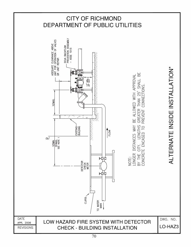
70

OUTSIDE
71

72

73

74

75

76

77

EXAMPLES OF SUBMITTAL DRAWINGS *
Examples are meant to show the quality of drawings to be submitted; type of backflow preventer/device, pipe sizes, valving, drainage, piping layout and dimensions specific the project being considered.
78
City of Richmond, VA DPU Cross Connection Control
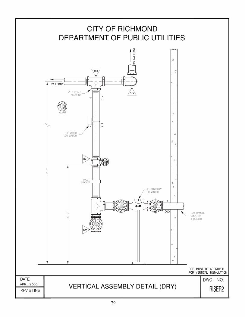
79

80

1

82
City of Richmond, VA DPU Cross Connection Control

83
City of Richmond, VA DPU Cross Connection Control

84
City of Richmond, VA DPU Cross Connection Control

PART IX
APPENDICIES
85 March 2015

APPENDIX A
CROSS CONNECTION CONTROL and
BACKFLOW PREVENTION ORDINANCE & CODE
86 March 2015

City of Richmond, VA DPU Cross Connection Control
AN ORDINANCE
NO. 84-261-234
ADOPTED OCT. 22, 1984
To amend the Richmond City Code of 1975, as amended, by adding in Chapter 31, Water, Gas and Sewers, Article III, Service Connections. Pipes, and Meters, Generally, Division 1, Generally, a new section numbered Section 31 – 34.10, concerning protection of the City’s water distribution system from a cross connection in any connection made to the water distribution system.
From 2004 Code [Current]:
Sec. 106-347. Prevention of cross connection or backflow. (a) The following words, terms and phrases, when used in this section, shall have the meanings ascribed to them in this subsection, except where the context clearly indicates a different meaning:
Backflow means the flow of water or other liquids, materials or substances into the pipes or into other facilities of the city's water distribution system from any source other than the city's normal sources of water, meeting standards for use and consumption of water, or from any alternate source of water meeting such standards which might be utilized by the city for the purpose of supplying water to the customers served by the water distribution system of the city.
Cross connection means any connection or structural arrangement, direct or indirect, to the city's water distribution system whereby a backflow can occur.
(b) To protect and ensure that the water distribution system of the city is pure and safe for public consumption as mandated by applicable state law and regulations, if any service connection for the supply of water to property from the water distribution system of the city may cause or result in a cross connection to the city's water distribution system, the director is authorized to require the abatement or control of such cross connection or possible cross connection in accordance with regulations to be promulgated by the director authorized in this section.
(c) The director shall promulgate rules and regulations pursuant to section 106-32 in order to prevent and control cross connection and backflow. Such rules and regulations shall be consistent with applicable state law and regulations and may provide for the termination of water service where necessary to protect the health of the citizens or where an owner or occupant of premises refuses to comply with the regulations.
87 March 2015

City of Richmond, VA DPU Cross Connection Control
APPENDIX B
REFERENCES
88 March 2015

City of Richmond, VA DPU Cross Connection Control
REFERENCES 1. AWWA – Cross Connection Control Manual
2. Cross Connection Manual – U.S. Environmental Protection Agency
3. City of Richmond Department of Public Utilities – Water and Sewer Specifications
4. Virginia Department of Health / State Water Works Regulations
5. The Code of the City of Richmond, Virginia
6. The American Society of Sanitary Engineers
7. Uniform Statewide Building Code
8. BOCA International Plumbing Code
89 March 2015

City of Richmond, VA DPU Cross Connection Control
APPENDIX C
VIRGINIA DEPARTMENT OF HEALTH WATERWORKS REGULATIONS
PART II ARTICLE 3 CROSS CONNECTION CONTROL AND
BACKFLOW PREVENTION IN WATERWORKS
90 March 2015

City of Richmond, VA DPU Cross Connection Control
12 VAC 5-590-590. Cross connections.
A. The purveyor shall not install, maintain, or allow to be installed a water service connection to any premises where cross connections to a waterworks or a consumer's water system may exist unless such cross connections are abated or controlled to the satisfaction of the water purveyor or the division.
B. The purveyor shall not install, maintain, or allow to be installed any connection
whereby water from an auxiliary water system may enter a waterworks or consumer's water system unless the auxiliary water system and the method of connection and use of such system shall have been approved by the water purveyor and by the division.
Statutory Authority §§ 32.1-12 and 32.1-170 of the Code of Virginia. Historical Notes Derived from VR355-18-006.02 § 2.26, eff. June 23, 1993.
12 VAC 5-590-600. Responsibilities.
A. General. Effective cross connection control requires the cooperation of the water purveyor, the
building official, the consumer, the Virginia Department of Health, and the backflow prevention device tester.
B. Water purveyor. 1. The purveyor shall establish or cause to be established and operate a cross connection control
and backflow prevention program consistent with the extent of the system and the type of consumer served. This program shall include at least one designated individual who shall be responsible for the inspection of the waterworks for cross connection and backflow prevention control. This program shall be carried out in accordance with the Uniform Statewide Building Code and shall be a continuing program.
2. Suggested elements of this program are contained in Appendix I. The purveyor has full responsibility for water quality and for the construction, maintenance, and operation of the waterworks beginning at the water source and ending at the service connection.
3. The purveyor shall have thorough inspections and operational tests made at least annually of backflow prevention devices which are required and installed at the service connection.
4. In the event of backflow of pollution or contamination into the waterworks, the purveyor shall promptly take or cause corrective action to confine and eliminate the pollution or contamination. The purveyor shall immediately notify the division when backflow occurs.
5. The purveyor shall take positive action to ensure that the waterworks is adequately protected at all times. If a cross connection exists or backflow occurs into a consumer's water system or if the pressure in the waterworks is lowered below 10 psi gauge, the purveyor may discontinue the water service to the consumer and water service shall not be restored until the deficiencies have been corrected or eliminated to the satisfaction of the purveyor.
Statutory Authority §§ 32.1-12 and 32.1-170 of the Code of Virginia. Historical Notes Derived from VR355-18-006.03 § 2.27, eff. August 1, 1991; amended, Virginia Register Volume 9, Issue 17, eff. June 23, 1993.
91 March 2015

12 VAC 5-590-610. Containment Policy. A. An approved backflow prevention device shall be installed at each service connection to a consumer's water system where, in the judgment of the water purveyor or the division, a health, pollution, or system hazard to the waterworks exists.
B. When, as a matter of practicality, the backflow prevention device cannot be installed at the service connection, the device may be located downstream of the service connection but prior to any unprotected takeoffs.
C. A backflow prevention device shall be installed at each service connection to a consumer's water system serving premises where the following conditions exist:
1. Premises on which any substance is handled in such a manner as to create an actual or potential hazard to a waterworks (this shall include premises having sources or systems containing process fluids or waters originating from a waterworks which are no longer under the control of the water purveyor);
2. Premises having internal cross connections that, in the judgment of the water purveyor or the division, may not be easily correctable or have intricate plumbing arrangements which make it impracticable to determine whether or not cross connections exist;
3. Premises where, because of security requirements or other prohibitions or restrictions, it is impossible or impractical to make a complete cross connection survey;
4. Premises having a repeated history of cross connections being established or reestablished;
5. Premises having fire protection systems utilizing combinations of sprinklers, fire loops, storage tanks, pumps, antifreeze protection, or auxiliary water sources including siamese connections (fire loops and sprinkler systems with openings not subject to flooding, and containing no antifreeze or other chemicals, no separate fire protection storage, or auxiliary sources, will not normally require backflow prevention); and
6. Other premises specified by the division or the purveyor when cause can be shown that a potential cross connection hazard not enumerated above exists.
D. Premises having booster pumps connected to the waterworks shall be equipped with a low pressure regulating or cutoff device to shut off the booster pump when the pressure in the waterworks drops to a minimum of 10 psi gauge.
E. An approved backflow prevention device shall be installed at each service connection to a consumer's water system serving, but not necessarily limited to, the following types of facilities:
1. Hospitals, mortuaries, clinics, veterinary establishments, nursing homes, and medical buildings;
2. Laboratories;
3. Piers, docks, and waterfront facilities;
4. Sewage treatment plants, sewage pumping stations, or storm water pumping stations;
92 March 2015

5. Food and beverage processing plants;
6. Chemical plants, dyeing plants and pharmaceutical plants;
7. Metal plating industries;
8. Petroleum or natural gas processing or storage plants;
9. Radioactive materials processing plants or nuclear reactors;
10. Car washes and laundries;
11. Lawn sprinkler systems, and irrigation systems;
12. Fire service systems;
13. Slaughter houses and poultry processing plants;
14. Farms where the water is used for other than household purposes;
15. Commercial greenhouses and nurseries;
16. Health clubs with swimming pools, therapeutic baths, hot tubs, or saunas;
17. Paper and paper products plants and printing plants;
18. Pesticide or exterminating companies and their vehicles with storage or mixing tanks;
19. Schools or colleges with laboratory facilities;
20. Highrise buildings (four or more stories);
21. Multiuse commercial, office, or warehouse facilities; and
22. Others specified by the purveyor or the division when reasonable cause can be shown for a potential backflow or cross connection hazard.
Statutory Authority §§ 32.1-12 and 32.1-170 of the Code of Virginia.
93 March 2015

City of Richmond, VA DPU Cross Connection Control
12 VAC 5-590-620. Type of Protection Required. The type of protection required shall depend on the degree of hazard which exists or may exist and on the method of potential backflow. Backflow occurs either by back pressure or by back siphonage.
The degree of hazard, either high, moderate, or low, is based on the nature of the contaminant; the potential of the health hazard; the probability of the backflow occurrence; and the effect on waterworks structures, equipment, and appurtenances used in the storage, collection, purification, treatment, and distribution of pure water.
Table 2.10 shall be used as a guide to determine the degree of hazard for any situation.
A. Air gaps give the highest degree of protection and shall be used whenever practical to do so in high hazard situations subject to back pressure.
B. An air gap separation and a reduced pressure principle backflow prevention device will protect against back pressure when operating properly. Vacuum breakers will not protect against back pressure, but will protect against back-siphonage when operating properly.
C. Backflow prevention devices consisting of dual independent check valves with or without an intermediate atmospheric vent shall only be used in low hazard situations.
D. Barometric loops are not acceptable.
E. An interchangeable connection or change-over device has limitations which prevent its use where back pressure is present or may occur, the auxiliary supply is not an approved source, or the waterworks line pressure is less than 20 psi. Since this type connection is one of the easiest to bypass, the use of this type device will be approved only as a temporary and continuously supervised arrangement. In most instances, an approved device or method must be included and approved by the purveyor and division.
F. Reduced pressure principle type backflow preventers shall not be installed in pits or areas subject to flooding.
Statutory Authority §§ 32.1-12 and 32.1-170 of the Code of Virginia.
94 March 2015

City of Richmond, VA DPU Cross Connection Control
12VAC5-590-630. Backflow Prevention Devices.
A. Any backflow prevention device shall be of the approved type and shall comply with the Uniform Statewide Building Code.
B. Any backflow prevention device shall be installed in a manner approved by the water purveyor and in accordance with the Uniform Statewide Building Code.
C. Existing backflow prevention devices approved by the purveyor and the division prior to the effective date of this chapter shall, except for inspection, testing, and maintenance requirements, be excluded from the requirements of 12VAC5-590-600 A and B if the water purveyor and the division are assured that the devices will protect the waterworks.
95 March 2015

TABLE 2.10. DETERMINATION OF DEGREE OF HAZARD
Premises with one or more of the following conditions shall be rated at the corresponding degree of hazard.
High Hazard The contaminant would be toxic, poisonous, noxious or unhealthy.
A health hazard would exist.
A high probability exists of a backflow occurrence either by back pressure or by back siphonage.
The contaminant would disrupt the service of piped water for human consumption.
Examples - sewage, used water, nonpotable water, auxiliary water systems, toxic or hazardous chemicals, etc.
Moderate Hazard The contaminant would only degrade the quality of the water aesthetically or impair the usefulness of the water.
A health hazard would not exist.
A moderate probability exists of a backflow occurrence either by back pressure or by back siphonage.
The contaminant would not seriously disrupt service of piped water for human consumption.
Examples - food stuff, nontoxic chemicals, nonhazardous chemicals, etc.
Low Hazard The contaminant would only degrade the quality of the water aesthetically.
A health hazard would not exist.
A low probability exists of the occurrence of backflow primarily by back siphonage.
The contaminant would not disrupt service of piped water.
Examples - food stuff, nontoxic chemicals, nonhazardous, chemicals, etc.
96 March 2015

APPENDIX D
CHECK LIST
97 March 2015
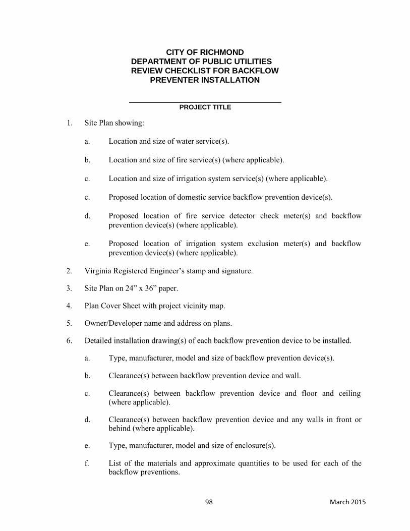
CITY OF RICHMOND DEPARTMENT OF PUBLIC UTILITIES REVIEW CHECKLIST FOR BACKFLOW
PREVENTER INSTALLATION
PROJECT TITLE
1. Site Plan showing:
a. Location and size of water service(s).
b. Location and size of fire service(s) (where applicable).
c. Location and size of irrigation system service(s) (where applicable).
c. Proposed location of domestic service backflow prevention device(s).
d. Proposed location of fire service detector check meter(s) and backflow prevention device(s) (where applicable).
e. Proposed location of irrigation system exclusion meter(s) and backflow prevention device(s) (where applicable).
2. Virginia Registered Engineer’s stamp and signature.
3. Site Plan on 24” x 36” paper.
4. Plan Cover Sheet with project vicinity map.
5. Owner/Developer name and address on plans.
6. Detailed installation drawing(s) of each backflow prevention device to be installed.
a. Type, manufacturer, model and size of backflow prevention device(s).
b. Clearance(s) between backflow prevention device and wall.
c. Clearance(s) between backflow prevention device and floor and ceiling (where applicable).
d. Clearance(s) between backflow prevention device and any walls in front or behind (where applicable).
e. Type, manufacturer, model and size of enclosure(s).
f. List of the materials and approximate quantities to be used for each of the backflow preventions.
98 March 2015

7. Water System designed to provide adequate domestic service and fire protection to Owner’s property. ____-inch diameter line required to adequately serve this project in accordance with the City standards.
8. Overall water plan submitted for phased projects.
a. Future locations of domestic, fire and irrigation system services shown on overall water plan (where applicable).
b. Future locations for domestic, fire and irrigation system backflow prevention devices shown on overall water plan (where applicable).
9. Any and all existing connections to property are shown on plans.
10. This project has been designed in accordance with the latest version of the City of Richmond DPU Standards and State regulations (whichever is more restrictive).
11. This project has been designed in accordance with the latest version of the City of Richmond DPU Cross Connection Control and Backflow Prevention Manual.
12. All proposed service lines connect to existing facilities that have previously accepted by the City for operations and maintenance.
I hereby certify that I have complied with the above and do hereby submit these plans for approval.
Signature - Engineer License Number
Name – Typed or Printed Date
99 March 2015