CROMPTON INSTRUMENTS ENERGY METERS · CROMPTON INSTRUMENTS ENERGY METERS. Features • Blue backlit...
36
ENERGY /// CROMPTON-INSTRUMENTS.COM/KWH.HTML CROMPTON INSTRUMENTS ENERGY METERS
Transcript of CROMPTON INSTRUMENTS ENERGY METERS · CROMPTON INSTRUMENTS ENERGY METERS. Features • Blue backlit...
ENERGY /// CROMPTON-INSTRUMENTS.COM/KWH.HTML
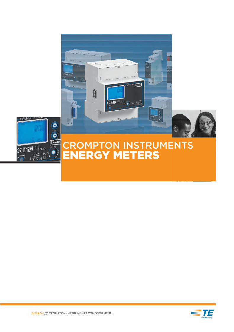
CROMPTON INSTRUMENTSENERGY METERS
Features• Blue backlit LCD• Direct and CT connection• Accuracy class 1 for active energy
and power• Accuracy class 2 for reactive
energy and power• The standard versions can
be combined with communication modules
• Energy registers for import and export
• Instantaneous active and reactive power display
• Sealable terminal covers• Storage of energy values
and configuration digital display (EEPROM)
• Tariff identifier display
Approvals
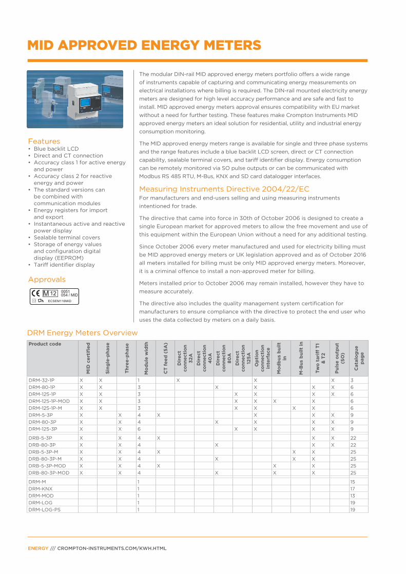
The modular DIN-rail MID approved energy meters portfolio offers a wide range
of instruments capable of capturing and communicating energy measurements on
electrical installations where billing is required. The DIN-rail mounted electricity energy
meters are designed for high level accuracy performance and are safe and fast to
install. MID approved energy meters approval ensures compatibility with EU market
without a need for further testing. These features make Crompton Instruments MID
approved energy meters an ideal solution for residential, utility and industrial energy
consumption monitoring.
The MID approved energy meters range is available for single and three phase systems
and the range features include a blue backlit LCD screen, direct or CT connection
capability, sealable terminal covers, and tariff identifier display. Energy consumption
can be remotely monitored via SO pulse outputs or can be communicated with
Modbus RS 485 RTU, M-Bus, KNX and SD card datalogger interfaces.
Measuring Instruments Directive 2004/22/ECFor manufacturers and end-users selling and using measuring instruments
intentioned for trade.
The directive that came into force in 30th of October 2006 is designed to create a
single European market for approved meters to allow the free movement and use of
this equipment within the European Union without a need for any additional testing.
Since October 2006 every meter manufactured and used for electricity billing must
be MID approved energy meters or UK legislation approved and as of October 2016
all meters installed for billing must be only MID approved energy meters. Moreover,
it is a criminal offence to install a non-approved meter for billing.
Meters installed prior to October 2006 may remain installed, however they have to
measure accurately.
The directive also includes the quality management system certification for
manufacturers to ensure compliance with the directive to protect the end user who
uses the data collected by meters on a daily basis.
MID APPROVED ENERGY METERS
ENERGY /// CROMPTON-INSTRUMENTS.COM/KWH.HTML
DRM Energy Meters Overview
Product code
MID
ce
rtifi
ed
Sin
gle
-ph
ase
Th
ree
-ph
ase
Mo
du
le w
idth
CT
fe
ed
(5
A)
Dir
ect
co
nn
ecti
on
3
2A
Dir
ect
co
nn
ecti
on
4
0A
Dir
ect
co
nn
ecti
on
8
0A
Dir
ect
co
nn
ecti
on
12
5A
Op
tio
n
co
nn
ecti
on
in
terf
ace
Mo
db
us
bu
ilt
in
M-B
us
bu
ilt
in
Tw
o t
ari
ff T
1 &
T2
Pu
lse
ou
tpu
t (S
O)
Cata
log
ue
p
ag
e
DRM-32-1P X X 1 X X X 3
DRM-80-1P X X 3 X X X X 6
DRM-125-1P X X 3 X X X X 6
DRM-125-1P-MOD X X 3 X X X X 6
DRM-125-1P-M X X 3 X X X X 6
DRM-5-3P X X 4 X X X X 9
DRM-80-3P X X 4 X X X X 9
DRM-125-3P X X 6 X X X X 9
DRB-5-3P X X 4 X X X 22
DRB-80-3P X X 4 X X X 22
DRB-5-3P-M X X 4 X X X 25
DRB-80-3P-M X X 4 X X X 25
DRB-5-3P-MOD X X 4 X X X 25
DRB-80-3P-MOD X X 4 X X X 25
DRM-M 1 15
DRM-KNX 1 17
DRM-MOD 1 13
DRM-LOG 1 19
DRM-LOG-PS 1 19

1
3 2
Supply terminals
32A direct
connection L↑- L↓
Space for the certification
data can be provided
on request MIDTerminals
connection
neutral network
Optic control IR
for external
communication
Readout selection
push button kWh
and other parameters
Terminals for
SO pulse output
Precision control LED
Display easy
to read
Display Unit ID
Active energy Tariff kWh Energy imported and exported
Active power Tariff kW Instantaneous value imported and exported
Current A
Voltage V
Power factor cosᶲFrequency Hz
Display Version
Active energy register in T1 import/export 32A
Instantaneous power active import/export 32A
FW release 32A
FW checksum 32A
PAGE 3
The energy-meters use an LCD display to give a clear reading and are used to
measure single-phase systems in residential, utility and industrial applications.
Monitoring of the energy-consumption is via two SO pulse outputs. The products
can be set up to communicate with Modbus RTU, M-Bus, KNX and SD card
datalogger interfaces, and thus can be used to analyse energy-consumption in order
to reduce to a minimum the running cost for industrial plants and buildings.
Active energy-meters for single-phase alternating current with a, 7 digits counter.
These meters have 1 S0 output generating pulses for remote processing of the active
energy measurements for 1 tariff.
Parameters
1 standard module housing, suitable for DIN-rail mountingDirect connection 32A
DisplayLiquid crystal display
1 kWh display and other parameters
2 Power export (supplied r)
3 Power import (absorbed R)
Parameters
Direct connection 32A
Features• Display LCD
• For direct connection 32A
• 7 digits for energy and other values indication
• Accuracy class 1 for active energy and power according to EN 50470-3 (B)
• Operating range current (Ist ... Imax) for direct connection 32A = 0.020 ... 32A
• Sealable terminal covers
• The standard versions are designed to be combined with the communication module
• DIN modules wide (18mm)
DRM ENERGY-METERS SINGLE-PHASE 32A/40A

ENERGY /// CROMPTON-INSTRUMENTS.COM/KWH.HTML
Technical Data
Display Units DRM - 32 - 1P direct connection 32A
SupplyRated control supply voltage Un V AC 230
Operating range voltage V AC 184 ... 276
Rated frequency fn Hz 50 ±2%
Rated power dissipation (max.) Pv VA (W) ≤8 (0.6)
Overload capabilityVoltage Un
continuousmomentary (1 s)
V ACV AC
276300
Current Imax
continuousmomentary (10 ms)
AA
32960
Display (readouts)Display type
LCD
digit dimensionsn° digits mm x mm
7 (2 decimals) 6 x 3
Active energy: 1 display, 7-digit kWh 0.00 ... 999999.9
Instantaneous tariff measurement 1 display, 1-digit
- -
1 T1
Display period refresh s 1
Measuring accuracy
Active energy and power
at 23 ±1°C, referred to nominal values acc.to EN 50470-3
class 1 B (±1)
Measuring inputType of connection
phase/N - direct
Operating range voltage phase/N V AC 184 ... 276
Current Iref A 5
Current Imin A 0.25
Operating range current (1st ... Imax)
direct connection A 0.02 ... 32
Frequency Hz 50 ±2%
Operating frequency Hz 44 ... 66
Input waveform - alternating
Starting current for energy measurement (Ist) mA 20
Differential % 1
Pulse output S0
Pulse output
acc.to EN 62053-31 for active energy - yes
Pulse quantity imp/kWh 1000
Pulse duration ms 90
Required voltage min. (max.) V AC (DC) 5 ... 230 ±5% (5 ... 300)
Permissible current pulse ON (max. 230V AC/DC) mA 90
Permissible current Impulse OFF (leakage cur. max. 230V AC/DC)
μA 1
Optical interfaceFront side (accuracy control)
LED imp/kWh 5000
Safety acc. to EN 50470-1Indoor meter - yes
Degree of pollution - 2
Operational voltage V AC 300
AC voltage test (EN 50470-3, 7.2) kV 4
Impulse voltage test 1.2/50 μs-kV 6
Protection class (EN 50470) class II
House material flame resistance
UL 94 class V0
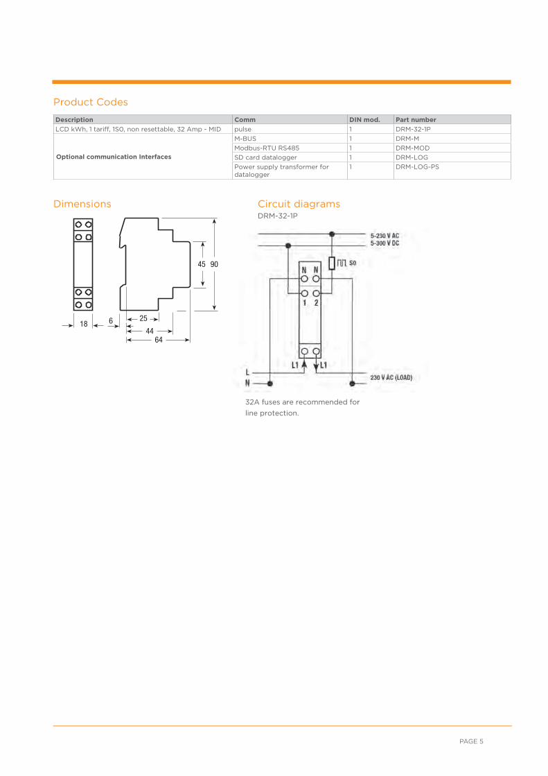
32A fuses are recommended for
line protection.
Description Comm DIN mod. Part number
LCD kWh, 1 tariff, 1S0, non resettable, 32 Amp - MID pulse 1 DRM-32-1P
Optional communication Interfaces
M-BUS 1 DRM-M
Modbus-RTU RS485 1 DRM-MOD
SD card datalogger 1 DRM-LOG
Power supply transformer fordatalogger
1 DRM-LOG-PS
Product Codes
Dimensions
PAGE 5
Circuit diagramsDRM-32-1P

Running or selected tariff
Power import (absorbed R)
Power export (supplied r)
Running active or reactive
power display
kVArh display
kWh display
Power unit
Displays capacitative
reactive power
Consumption bar
display
(percentage of Pmax)
Energy value
Displays inductive
reactive power
Full scale current
indication
Backlighting makes
display easy to read
Terminals for 2
SO pulse outlet
and Tariffs
change command
Precision control
LED
Space for the certification data can
be provided on request MID
Optic control IR for
external communication
Supply terminals 80A or
125A direct connection
Parameters set as
addresses, baudrate
Note for Modbus and
M-bus versions only
Features• Blue backlit LCD
• Direct connection 80A/125A
• 8 digit display
• Accuracy class 1 for active energy
• Accuracy class 2 for reactive energy
• The standard versions can be combined with the communication modules
• Energy register for import and export
• Sealable terminal covers
• 3 DIN modules wide (52mm)
• Storage of energy values and configuration digital display (EEPROM)
• Tariff identifier display for active and reactive energy.
DRM ENERGY-METERS SINGLE-PHASE 80A/125A
ENERGY /// CROMPTON-INSTRUMENTS.COM/KWH.HTML
These meters are used to measure the energy consumption in single-phase systems
in residential, utility and industrial applications, and use a blue backlit LCD screen
to give clear readings. Monitoring of the energy-consumption is via two SO pulse
outputs. The products can be set up to communicate with Modbus RTU, M-Bus,
KNX and SD card Datalogger interfaces, and thus can be used to analyse energy-
consumption in order to reduce to a minimum the running cost for Industrial plants
and buildings.
A single phase energy meter with an 8 digit, 2 decimal, display showing the total
energy reading. The meters have 2 SO outputs generating pulses for remote
processing of active and reactive energy and 2 Tariffs.
Parameters
DisplayLiquid crystal display with illuminated blue background.
Direct connection 80A/125A
Display Unit
Active energyTariff 1 Tariff 2
kWh kWh
Import, exportImport, export
Reactive energy Tariff 1 Tariff 2
kVArh kVArh
Import, exportImport, export
Active power (k-M) W Import, export
Reactive power (k-M) VAr Import, export
3 standard module housing, suitable for DIN-rail mountingDirect connection 80A and 125A
Readout selection
push button
kWh and W
or kVArh and VAr

Display Units DRM - 80 - 1P, DRM - 125 - 1P DRM - 125 - 1P - MOD DRM - 125 - 1P - M
SupplyCertified voltage range Un V AC 230 ±20% 230 ±20% 230 ±20%
Operating voltage range V AC 110 ... 276 110 ... 276V 110 ... 276
Certified frequency fn Hz 50 ±2% 50 ±2% 50 ±2%
Operating frequency range Hz 44 ... 66 44 ... 66 44 ... 66
Rated power dissipation (max.) Pv VA (W) <8 (0.6) ≤8 (0.6) ≤8 (0.6)
Overload capabilityVoltage Un continuous V AC 276 276 276
Momentary (1 s) V AC 300 300 300
Current Imax continuous A 80 or 125 125 125
Momentary (10 ms) A 2400 or 3750 3750 3750
Display (readouts)Display type LCD n° digits 8 (2 decimal) 8 (2 decimal) 8 (2 decimal)
Digit dimensions Mm 6.00 x 3 6 x 3 6 x 3
Active energy: 1 display, 7-digit tariffs 2 kWh 0.01 0.01 0.01
+ display import or export (arrow) overflow kWh 999999.99 999999.99 999999.99
Reactive energy: 1 display, 7-digit tariffs 2 kvarh 0.01 0.01 0.01
+ display import or export (arrow) overflow kvarh 999999.99 999999.99 999999.99
Instantaneous active power: 1 display, 3-digit W, kW, MW 000 ... 999 000 ... 999
Instantaneous reactive power: 1 display, 3-digit
VAr, kVAr, MVAr
000 ... 999 000 ... 999 000 ... 999
Instantaneous tariff measurement 1 1 1
Display period refresh s 1 1 1
Measuring accuracyat 23 ±1°C, referred to nominal values
Active energy and power acc.to EN 50470-3 B (1%) class 1 B (1%) B (1%)
Reactive energy and power acc. to EN 62053-23 2% class 2 2% 2%
Measuring input
Type of connection phase/N direct direct direct
Operating range voltage V AC 110 ... 276 110 ... 276 110 ... 276
Current Iref A 5A 5 5
Current Imin A 0.25A 0.25 0.25
Operating range current (Ist ... Imax) direct connection A 0.020 ... 80 or 125 0.020 ... 125 0.020 ... 125
Operating frequency Hz 44 ... 66 44 ... 66 44 ... 66
Differential % 1 1 1
Pulse output S0 acc.to EN 62053-31Pulse output for active and reactive energy T1 and T2 yes
Pulse quantity imp/kWh 500
Pulse duration ms 30 or 50
Required voltage V AC (DC) 5 ... 230 ±5% (5 ... 300) min. (max)
Permissible current pulse ON (max. 230V AC/DC)
mA90
Permissible current Impulse OFF (leakage cur. max. 230V AC/DC) 1
Embedded communicationModbus RTU RS-485 - 3 wires
µAbps up to 38.400 -
M-Bus RS-485 - 2 wires bps - up to 9.600 bps
Safety acc. to EN 50470-1Degree of pollution 2 2 2
Operational voltage V AC 300 300 300
AC voltage test (EN 50470-3, 7.2) kV 4 4 4
Impulse voltage test 1.2/50 µs-kV 6 6 6
Protection class (EN 50470) class II II II
Housing material flame resistance UL 94 class V0 V0 V0
Environmental conditionsOperating temperature °C -10 ... +55 -10 ... +55 -10 ... +55
Limit temperature of transportation and storage °C -25 ... +70 -25 ... +70 -25 ... +70
Relative humidity (not condensation) % ≤80 ≤80 ≤80
Degree protection housing when mounted in front (terminal)
IP51(*)/IP20 IP51(*)/IP20 IP51(*)/IP20
Technical Data
(*) For the installation in a cabinet at least with IP51 protection.
PAGE 7
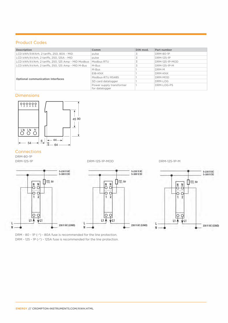
Product Codes
Description Comm DIN mod. Part number
LCD kWh/kWArh, 2 tariffs, 2S0, 80A - MID pulse 3 DRM-80-1P
LCD kWh/kVArh, 2 tariffs, 2S0, 125A - MID pulse 3 DRM-125-1P
LCD kWh/kVArh, 2 tariffs, 2S0, 125 Amp - MID Modbus Modbus RTU 3 DRM-125-1P-MOD
LCD kWh/kVArh, 2 tariffs, 2S0, 125 Amp - MID M-Bus M-Bus 3 DRM-125-1P-M
Optional communication Interfaces
M-Bus 1 DRM-M
EIB-KNX 1 DRM-KNX
Modbus-RTU RS485 1 DRM-MOD
SD card datalogger 1 DRM-LOG
Power supply transformer for datalogger
1 DRM-LOG-PS
DRM - 80 - 1P (-*) - 80A fuse is recommended for the line protection.
DRM - 125 - 1P (-*) - 125A fuse is recommended for the line protection.
Dimensions
ConnectionsDRM-80-1P
DRM-125-1P DRM-125-1P-MOD DRM-125-1P-M
ENERGY /// CROMPTON-INSTRUMENTS.COM/KWH.HTML
Backlighting makes
display easy to read
Terminals for 2 SO
pulse outlet and
Tariffs change
command
CT selection (5 to
10.000/5A - 5A
step) CT - 5A only
Precision control LED
Space for the certification
data can be provided on
request MID
Optic control IR for
external communcation
Supply terminals
CT connection
(5 to 10.000A)
Readout selection
push button
kWh and W
or kVArh and VAr
Displays inductive
and reactive power
Running tariff
Power import (absorbed )
Power export (supplied )
Running active or reactive power display
(M) - kVArh display(M) - kWh display
Energy line (L1-2-3) or ∑L
Displays capacitative
and reactive power
instantaneous power
bar display
(percentage of Pmax)
Energy value
Power unit
CT primary current
CT-5A only
Display Unit ID
Active energy Tariff 1 Tariff 2
kWh kWh
Energy imported and exportedEnergy imported and exported
Reactive energy Tariff 1 kVArh Energy imported and exported
Tariff 2 kVArh Energy imported and exported
Active power (M-k)-W Utilization and instantaneous value
Reactive power (M-k)-VAr Utilization and instantaneous value
Connection errors Phase Err
Primary transformer 5 ... 9999 A CT (current transformer) (CT 5A only)
PAGE 9
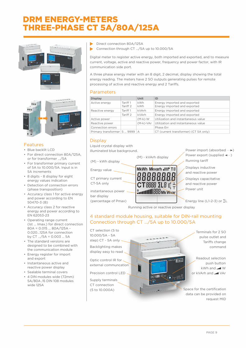
Digital meter to register active energy, both imported and exported, and to measure
current, voltage, active and reactive power, frequency and power factor, with IR
communication side port.
A three phase energy meter with an 8 digit, 2 decimal, display showing the total
energy reading. The meters have 2 SO outputs generating pulses for remote
processing of active and reactive energy and 2 Tariffs.
Parameters
4 standard module housing, suitable for DIN-rail mountingConnection through CT .../5A up to 10.000/5A
DisplayLiquid crystal display with
illuminated blue background.
Direct connection 80A/125A
Connection through CT .../5A up to 10.000/5A
Features• Blue backlit LCD
• For direct connection 80A/125A, or for transformer .../5A
• For transformer primary current of 5A to 10.000/5A. Input is in 5A increments
• 8 digits - 8 display for eight energy values indication
• Detection of connection errors (phase transposition)
• Accuracy class 1 for active energy and power according to EN 50470-3 (B)
• Accuracy class 2 for reactive energy and power according to EN 62053-23
• Operating range current (Ist ... Imax.) for direct connection 80A = 0.015 ... 80A/125A - 0.020...125A for connection by CT .../5A = 0.003 ... 5A
• The standard versions are designed to be combined with the communication module
• Energy register for import and export
• Instantaneous active and reactive power display
• Sealable terminal covers
• 4 DIN modules wide (72mm) 5A/80A /6 DIN 108 modules wide 125A
DRM ENERGY-METERS THREE-PHASE CT 5A/80A/125A
ENERGY /// CROMPTON-INSTRUMENTS.COM/KWH.HTML
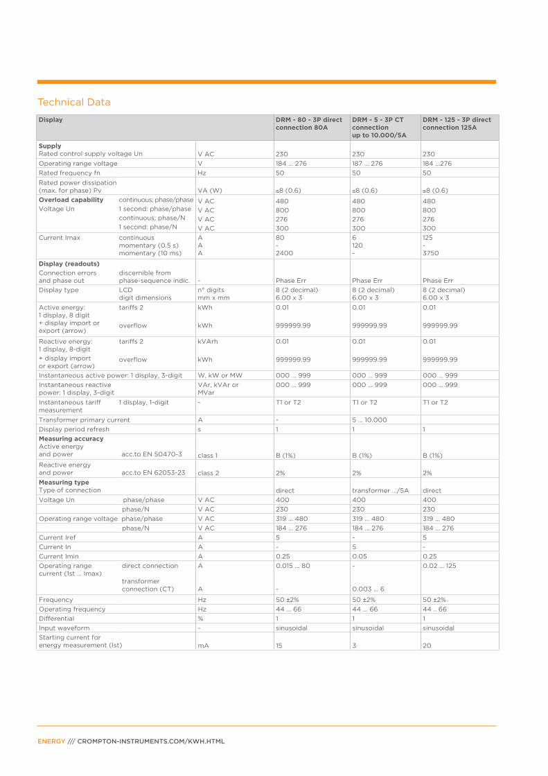
Technical Data
Display DRM - 80 - 3P direct connection 80A
DRM - 5 - 3P CT connection up to 10.000/5A
DRM - 125 - 3P direct connection 125A
SupplyRated control supply voltage Un V AC 230 230 230
Operating range voltage V 184 ... 276 187 ... 276 184 ...276
Rated frequency fn Hz 50 50 50
Rated power dissipation (max. for phase) Pv VA (W) ≤8 (0.6) ≤8 (0.6) ≤8 (0.6)
Overload capability
Voltage Un
continuous; phase/phase
1 second: phase/phase
continuous; phase/N
1 second: phase/N
V AC
V AC
V AC
V AC
480
800
276
300
480
800
276
300
480
800
276
300
Current Imax continuous momentary (0.5 s) momentary (10 ms)
A A A
80 - 2400
6120-
125-3750
Display (readouts)
Connection errors and phase out
discernible from phase-sequence indic.
-
Phase Err
Phase Err
Phase Err
Display type LCD digit dimensions
n° digits mm x mm
8 (2 decimal) 6.00 x 3
8 (2 decimal)6.00 x 3
8 (2 decimal)6.00 x 3
Active energy: 1 display, 8 digit+ display import or export (arrow)
tariffs 2
overflow
kWh
kWh
0.01
999999.99
0.01
999999.99
0.01
999999.99
Reactive energy: 1 display, 8-digit
+ display import or export (arrow)
tariffs 2
overflow
kVArh
kWh
0.01
999999.99
0.01
999999.99
0.01
999999.99
Instantaneous active power: 1 display, 3-digit W, kW or MW 000 ... 999 000 ... 999 000 ... 999
Instantaneous reactive power: 1 display, 3-digit
VAr, kVAr or MVar
000 ... 999 000 ... 999 000 ... 999
Instantaneous tariff measurement
1 display, 1-digit - T1 or T2 T1 or T2 T1 or T2
Transformer primary current A - 5 ... 10.000
Display period refresh s 1 1 1
Measuring accuracyActive energy and power acc.to EN 50470-3 class 1 B (1%) B (1%) B (1%)
Reactive energyand power acc.to EN 62053-23 class 2 2% 2% 2%
Measuring typeType of connection direct transformer .../5A direct
Voltage Un phase/phase V AC 400 400 400
phase/N V AC 230 230 230
Operating range voltage phase/phase V AC 319 ... 480 319 ... 480 319 ... 480
phase/N V AC 184 ... 276 184 ... 276 184 ... 276
Current Iref A 5 - 5
Current In A - 5 -
Current Imin A 0.25 0.05 0.25
Operating range current (1st ... Imax)
direct connection transformer connection (CT)
A
A
0.015 ... 80
-
-
0.003 ... 6
0.02 ... 125
Frequency Hz 50 ±2% 50 ±2% 50 ±2%
Operating frequency Hz 44 ... 66 44 ... 66 44 .. 66
Differential % 1 1 1
Input waveform - sinusoidal sinusoidal sinusoidal
Starting current for energy measurement (Ist) mA 15 3 20
Display DRM - 80 - 3P direct connection 80A
DRM - 5 - 3P CT connection up to 10.000/5A
DRM - 125 - 3P direct connection 125A
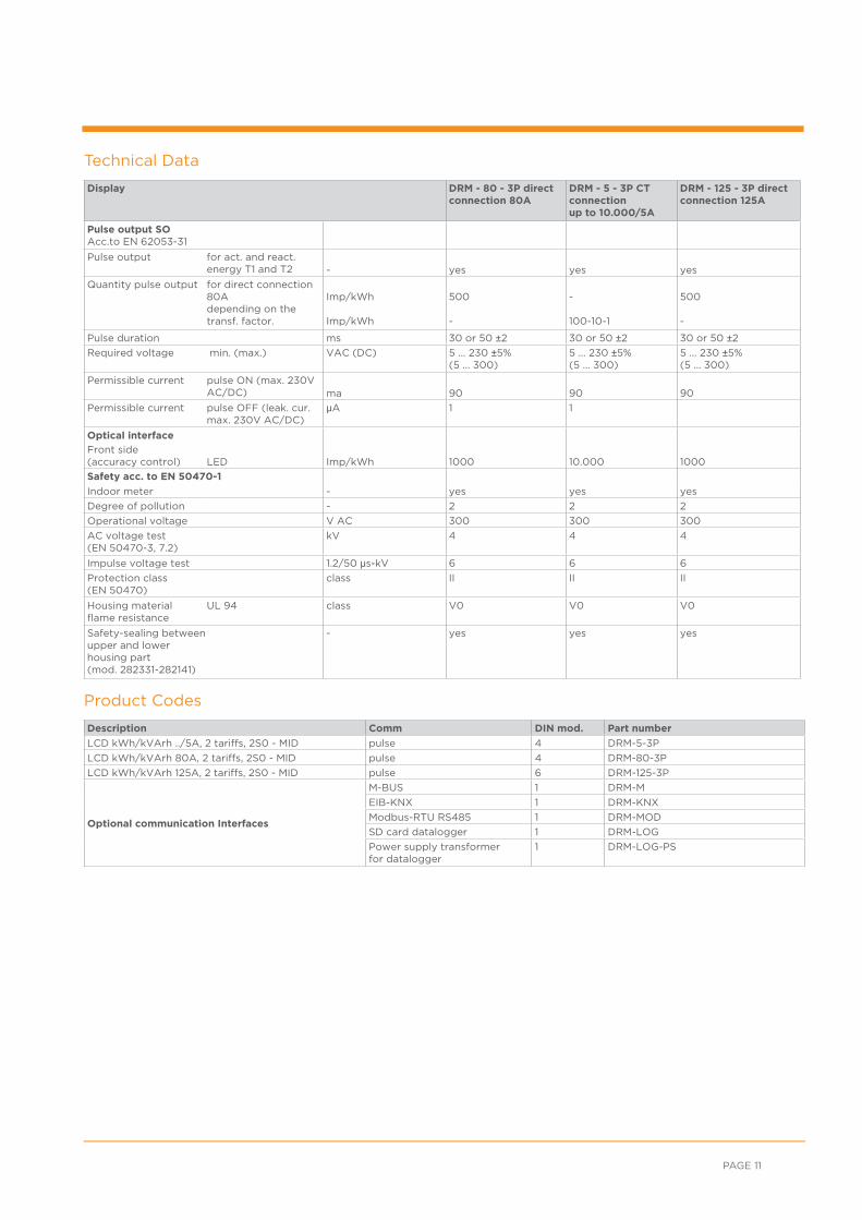
Pulse output SO Acc.to EN 62053-31
Pulse output for act. and react. energy T1 and T2 - yes yes yes
Quantity pulse output for direct connection 80A depending on the transf. factor.
Imp/kWh
Imp/kWh
500
-
-
100-10-1
500
-
Pulse duration ms 30 or 50 ±2 30 or 50 ±2 30 or 50 ±2
Required voltage min. (max.) VAC (DC) 5 ... 230 ±5% (5 ... 300)
5 ... 230 ±5% (5 ... 300)
5 ... 230 ±5%(5 ... 300)
Permissible current pulse ON (max. 230V AC/DC) ma 90 90 90
Permissible current
pulse OFF (leak. cur. max. 230V AC/DC)
μA 1 1
Optical interface
Front side (accuracy control)
LED Imp/kWh 1000 10.000 1000
Safety acc. to EN 50470-1
Indoor meter - yes yes yes
Degree of pollution - 2 2 2
Operational voltage V AC 300 300 300
AC voltage test (EN 50470-3, 7.2)
kV 4 4 4
Impulse voltage test 1.2/50 μs-kV 6 6 6
Protection class (EN 50470)
class II II II
Housing material flame resistance
UL 94 class V0 V0 V0
Safety-sealing between upper and lower housing part (mod. 282331-282141)
- yes yes yes
PAGE 11
Technical Data
Description Comm DIN mod. Part number
LCD kWh/kVArh ../5A, 2 tariffs, 2S0 - MID pulse 4 DRM-5-3P
LCD kWh/kVArh 80A, 2 tariffs, 2S0 - MID pulse 4 DRM-80-3P
LCD kWh/kVArh 125A, 2 tariffs, 2S0 - MID pulse 6 DRM-125-3P
Optional communication Interfaces
M-BUS 1 DRM-M
EIB-KNX 1 DRM-KNX
Modbus-RTU RS485 1 DRM-MOD
SD card datalogger 1 DRM-LOG
Power supply transformer for datalogger
1 DRM-LOG-PS
Product Codes

A fuse of 80A is recommended for the line protection.
A fuse of 6A is recommended for the line protection. Current transformers must
not be operated with open terminals since dangerous high voltages might occur
which may result in personal injuries and property damage. In addition to this, the
transformers are exposed to thermal overload.
A fuse of 125A is recommended for the line protection.
Wire N needs to be connected to the meter.
DimensionsDRM-80-3P
DRM-5-3P DRM-5-3P
DRM-125-3PDRM-125-3P
Circuit diagramsDRM-80-3P
ENERGY /// CROMPTON-INSTRUMENTS.COM/KWH.HTML
A fuse of 80A is recommended for the line protection.
Side IR for communication
with e.g. energy-meters
Modbus interface
Reset push button
Control and operation LED
Modbus interface
Supply terminals
A fuse of 125A is recommended for the line protection.
Wire N needs to be connected to the meter.
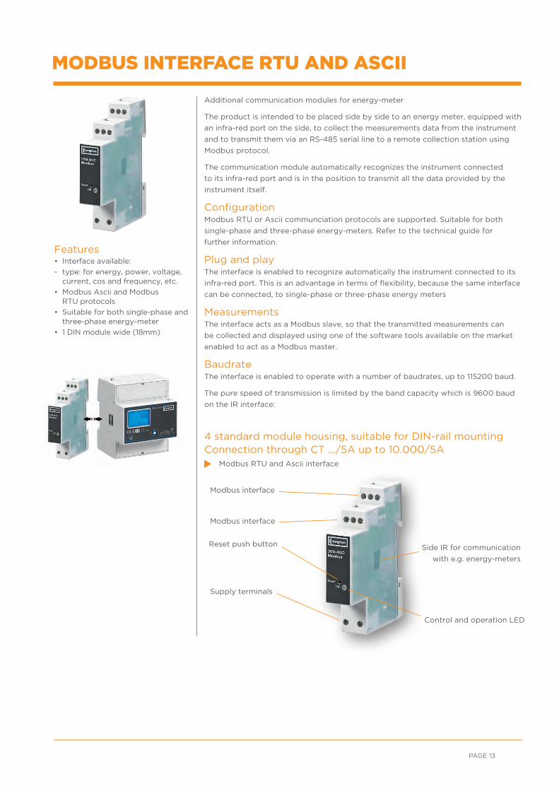
Additional communication modules for energy-meter
The product is intended to be placed side by side to an energy meter, equipped with
an infra-red port on the side, to collect the measurements data from the instrument
and to transmit them via an RS-485 serial line to a remote collection station using
Modbus protocol.
The communication module automatically recognizes the instrument connected
to its infra-red port and is in the position to transmit all the data provided by the
instrument itself.
ConfigurationModbus RTU or Ascii communciation protocols are supported. Suitable for both
single-phase and three-phase energy-meters. Refer to the technical guide for
further information.
Plug and playThe interface is enabled to recognize automatically the instrument connected to its
infra-red port. This is an advantage in terms of flexibility, because the same interface
can be connected, to single-phase or three-phase energy meters
MeasurementsThe interface acts as a Modbus slave, so that the transmitted measurements can
be collected and displayed using one of the software tools available on the market
enabled to act as a Modbus master.
BaudrateThe interface is enabled to operate with a number of baudrates, up to 115200 baud.
The pure speed of transmission is limited by the band capacity which is 9600 baud
on the IR interface:
4 standard module housing, suitable for DIN-rail mountingConnection through CT .../5A up to 10.000/5A
Modbus RTU and Ascii interface
Features• Interface available:
- type: for energy, power, voltage, current, cos and frequency, etc.
• Modbus Ascii and Modbus RTU protocols
• Suitable for both single-phase and three-phase energy-meter
• 1 DIN module wide (18mm)
MODBUS INTERFACE RTU AND ASCII
PAGE 13
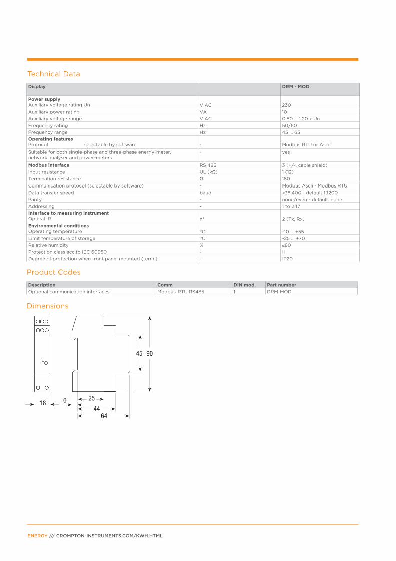
Technical Data
Display DRM - MOD
Power supplyAuxiliary voltage rating Un V AC 230
Auxiliary power rating VA 10
Auxiliary voltage range V AC 0.80 ... 1.20 x Un
Frequency rating Hz 50/60
Frequency range Hz 45 ... 65
Operating features Protocol selectable by software
-
Modbus RTU or Ascii
Suitable for both single-phase and three-phase energy-meter, network analyser and power-meters
- yes
Modbus interface RS 485 3 (+/-, cable shield)
Input resistance UL (kΩ) 1 (12)
Termination resistance Ω 180
Communication protocol (selectable by software) - Modbus Ascii - Modbus RTU
Data transfer speed baud ≤38.400 - default 19200
Parity - none/even - default: none
Addressing - 1 to 247
Interface to measuring instrumentOptical IR n° 2 (Tx, Rx)
Environmental conditionsOperating temperature °C -10 ... +55
Limit temperature of storage °C -25 ... +70
Relative humidity % ≤80
Protection class acc.to IEC 60950 - II
Degree of protection when front panel mounted (term.) - IP20
ENERGY /// CROMPTON-INSTRUMENTS.COM/KWH.HTML
Description Comm DIN mod. Part number
Optional communication interfaces Modbus-RTU RS485 1 DRM-MOD
Product Codes
Dimensions
Side IR for communication
with e.g. energy-meters
Control and operation LED
M-Bus connection
M-BUS INTERFACE
PAGE 15
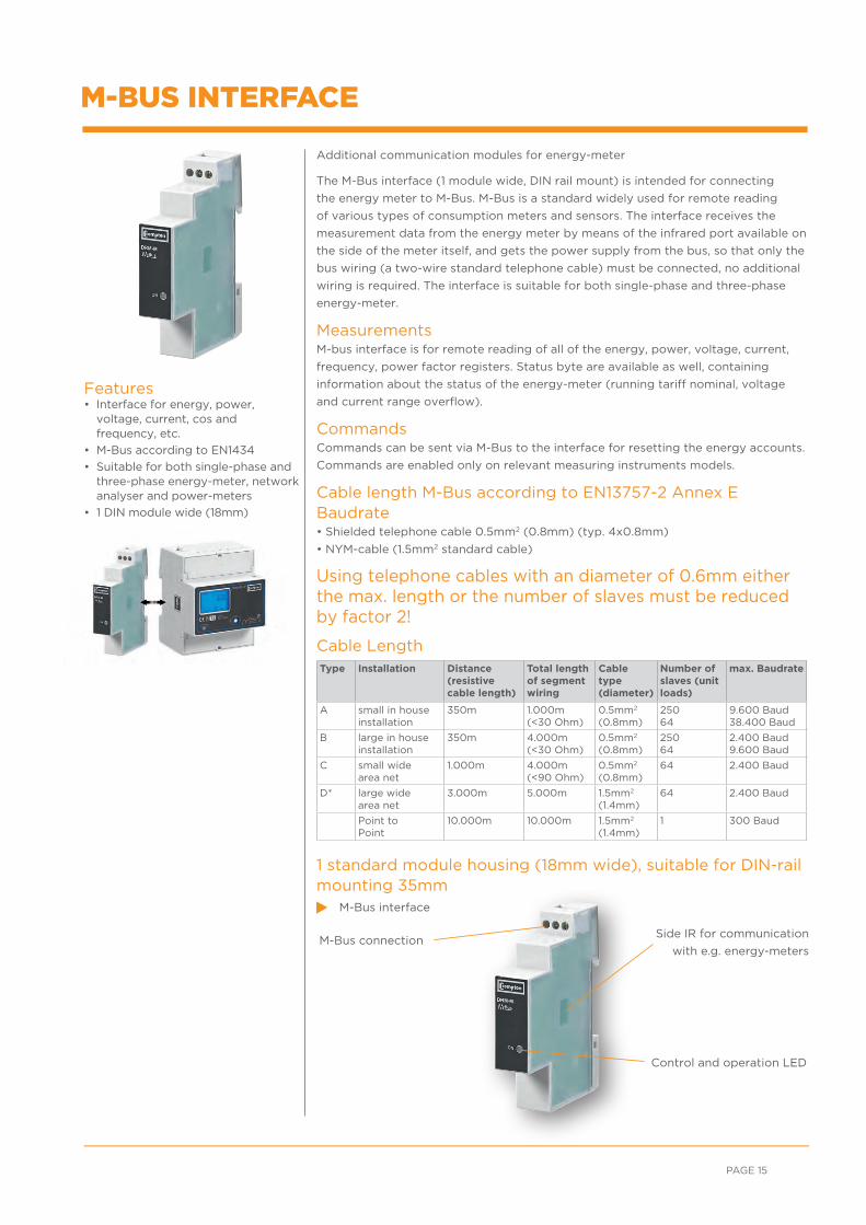
Additional communication modules for energy-meter
The M-Bus interface (1 module wide, DIN rail mount) is intended for connecting
the energy meter to M-Bus. M-Bus is a standard widely used for remote reading
of various types of consumption meters and sensors. The interface receives the
measurement data from the energy meter by means of the infrared port available on
the side of the meter itself, and gets the power supply from the bus, so that only the
bus wiring (a two-wire standard telephone cable) must be connected, no additional
wiring is required. The interface is suitable for both single-phase and three-phase
energy-meter.
MeasurementsM-bus interface is for remote reading of all of the energy, power, voltage, current,
frequency, power factor registers. Status byte are available as well, containing
information about the status of the energy-meter (running tariff nominal, voltage
and current range overflow).
CommandsCommands can be sent via M-Bus to the interface for resetting the energy accounts.
Commands are enabled only on relevant measuring instruments models.
Cable length M-Bus according to EN13757-2 Annex EBaudrate• Shielded telephone cable 0.5mm2 (0.8mm) (typ. 4x0.8mm)
• NYM-cable (1.5mm2 standard cable)
Using telephone cables with an diameter of 0.6mm either the max. length or the number of slaves must be reduced by factor 2!
Cable Length
1 standard module housing (18mm wide), suitable for DIN-rail mounting 35mm
M-Bus interface
Features• Interface for energy, power,
voltage, current, cos and frequency, etc.
• M-Bus according to EN1434
• Suitable for both single-phase and three-phase energy-meter, network analyser and power-meters
• 1 DIN module wide (18mm)
Type Installation Distance (resistive cable length)
Total length of segment wiring
Cable type (diameter)
Number of slaves (unit loads)
max. Baudrate
A small in houseinstallation
350m 1.000m(<30 Ohm)
0.5mm2
(0.8mm)25064
9.600 Baud38.400 Baud
B large in houseinstallation
350m 4.000m(<30 Ohm)
0.5mm2
(0.8mm)25064
2.400 Baud9.600 Baud
C small widearea net
1.000m 4.000m(<90 Ohm)
0.5mm2
(0.8mm)64 2.400 Baud
D* large widearea net
3.000m 5.000m 1.5mm2
(1.4mm)64 2.400 Baud
Point to Point
10.000m 10.000m 1.5mm2
(1.4mm)1 300 Baud
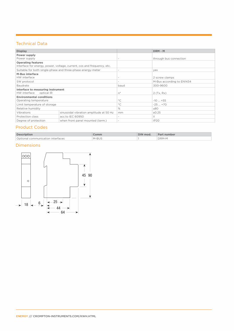
Technical Data
Display DRM - M
Power supplyPower supply - through bus connection
Operating features Interface for energy, power, voltage, current, cos and frequency, etc.
Suitable for both single-phase and three-phase energy-meter - yes
M-Bus interfaceHW interface - 2 screw clamps
SW protocol - M-Bus according to EN1434
Baudrate baud 300-9600
Interface to measuring instrumentHW interface optical IR n° 2 (Tx, Rx)
Environmental conditionsOperating temperature °C -10 ... +55
Limit temperature of storage °C -25 ... +70
Relative humidity % ≤80
Vibrations sinusoidal vibration amplitude at 50 Hz mm ±0.25
Protection class acc.to IEC 60950 - II
Degree of protection when front panel mounted (term.) - IP20
ENERGY /// CROMPTON-INSTRUMENTS.COM/KWH.HTML
Description Comm DIN mod. Part number
Optional communication interfaces M-BUS 1 DRM-M
Product Codes
Dimensions

Side IR for communication
with e.g. energy-meters
Configuration LED
KNX interface connection
KNX INTERFACE
Additional communication modules for energy-meter
The KNX interface (1 module wide, DIN rail mount) is intended for connecting the
energy meter to KNX bus. KNX bus is widely used for home and building control
applications. The interface receives the measurement data from the energy meter
by means of the infrared port available on the side of the energy meter itself, and
gets the power supply from the bus. Only the bus wiring (twisted pair) must be
connected, no additional wiring is required. The interface is suitable for both single-
phase and three-phase energy-meter.
ConfigurationThe interface is provided with an application program to be imported in ETS3,
in order to allow the configuration of the communication. ETS3 is the standard
software for KNX systems configuration.
MeasurementsAll the active and reactive energy, voltage, current, active, reactive, apparent power,
power factor, frequency registers available on the measuring instrument can be
transmitted over the bus. Transmission modes are available: transmission on request,
automatic transmission based on adjustable energy account increment (for instance
a message every 10 KWh). Status bytes are available as well, containing information
about the status of the energy meter and the load (load type, running Tariff, energy
import or export and so on). (Some measurements and status information are
available only on selected models).
Voltage limitsUpper and lower voltage limits can be set via ETS3. A warning message will be sent
over the bus by the interface, in case the voltage value goes beyond the limits.
Energy resetCommands can be sent via bus to the interface for resetting the energy accounts
(enabled only on selected measuring instruments models).
1 standard module housing (18mm wide), suitable for DIN-rail mounting 35mm.
KNX interface
Features• Interface for energy register and
power measurements, etc.
• Communication in compliance with KNX standard for home and building control
• Configuration via ETS3
• Energy registers transmitted as float values (EIS9)
• Suitable for both single-phase and three-phase energy-meter
• 1 DIN module wide (18mm)
PAGE 17

Technical Data
Display DRM - M
Power supplyPower supply - through bus connection
Operating features Interface for energy register and power measurements
Communication in compliance with KNX
standard for home and building control
Energy registers transmitted as float values (DPT 13. xxx)
Power registers transmitted as float values (DPT 14. xxx)
Status bytes available
Energy account remote reset available (not active some energy-meters models)
Suitable for both single-phase and three-phase Energy-meter, Network analyser and Power-meters - yes
Configuration via ETS3
KNX interface HW interface - black/red terminals for connection to Twisted
Pair type 1 (TP-1)
Bitrate - 9600 bps
Interface to measuring instrumentHardware interface optical IR n° 2 (Tx, Rx)
Environmental conditionsOperating temperature
°C -10 ... +55
Temperature of storage °C -25 ... +70
Relative humidity % ≤80
Protection class acc.to EN 60664 - II
Degree of protection housing when mounted - IP20
ENERGY /// CROMPTON-INSTRUMENTS.COM/KWH.HTML
Description Comm DIN mod. Part number
Optional communication interfaces EIB-KNX 1 DRM-KNX
Product Codes
Dimensions
• • The recording will start within 8 seconds; don’t pull the SD card.
• The IR communication with
meter is active.
• Less than 25% of memory
is available.
• Is allowed to pull the SD card.
• The recording is started; don’t pull the SD card.
• The SD card is full.
• No communication is being.
LED-REC
Side IR for communication
with e.g. energy-meters
LED-MEM
LED-I / R
Card from
1 to 8 gigabytes
Lowest voltage
supply terminals
• LED blinking
• LED ON
• LED OFF
• LED irrelevant
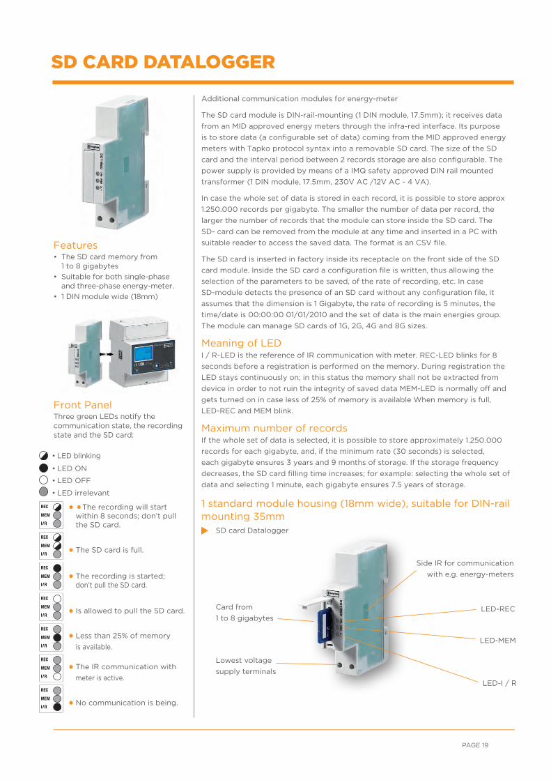
SD CARD DATALOGGER
Additional communication modules for energy-meter
The SD card module is DIN-rail-mounting (1 DIN module, 17.5mm); it receives data
from an MID approved energy meters through the infra-red interface. Its purpose
is to store data (a configurable set of data) coming from the MID approved energy
meters with Tapko protocol syntax into a removable SD card. The size of the SD
card and the interval period between 2 records storage are also configurable. The
power supply is provided by means of a IMQ safety approved DIN rail mounted
transformer (1 DIN module, 17.5mm, 230V AC /12V AC - 4 VA).
In case the whole set of data is stored in each record, it is possible to store approx
1.250.000 records per gigabyte. The smaller the number of data per record, the
larger the number of records that the module can store inside the SD card. The
SD- card can be removed from the module at any time and inserted in a PC with
suitable reader to access the saved data. The format is an CSV file.
The SD card is inserted in factory inside its receptacle on the front side of the SD
card module. Inside the SD card a configuration file is written, thus allowing the
selection of the parameters to be saved, of the rate of recording, etc. In case
SD-module detects the presence of an SD card without any configuration file, it
assumes that the dimension is 1 Gigabyte, the rate of recording is 5 minutes, the
time/date is 00:00:00 01/01/2010 and the set of data is the main energies group.
The module can manage SD cards of 1G, 2G, 4G and 8G sizes.
Meaning of LEDI / R-LED is the reference of IR communication with meter. REC-LED blinks for 8
seconds before a registration is performed on the memory. During registration the
LED stays continuously on; in this status the memory shall not be extracted from
device in order to not ruin the integrity of saved data MEM-LED is normally off and
gets turned on in case less of 25% of memory is available When memory is full,
LED-REC and MEM blink.
Maximum number of recordsIf the whole set of data is selected, it is possible to store approximately 1.250.000
records for each gigabyte, and, if the minimum rate (30 seconds) is selected,
each gigabyte ensures 3 years and 9 months of storage. If the storage frequency
decreases, the SD card filling time increases; for example: selecting the whole set of
data and selecting 1 minute, each gigabyte ensures 7.5 years of storage.
1 standard module housing (18mm wide), suitable for DIN-rail mounting 35mm
SD card Datalogger
Features• The SD card memory from
1 to 8 gigabytes
• Suitable for both single-phase and three-phase energy-meter.
• 1 DIN module wide (18mm)
Front PanelThree green LEDs notify the communication state, the recording state and the SD card:
PAGE 19
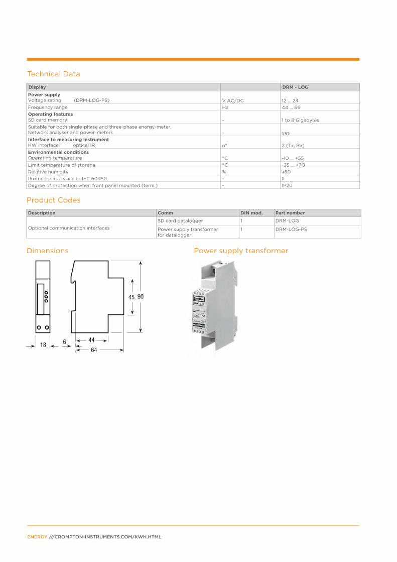
Technical Data
Display DRM - LOG
Power supply Voltage rating (DRM-LOG-PS) V AC/DC 12 ... 24
Frequency range Hz 44 ... 66
Operating featuresSD card memory - 1 to 8 Gigabytes
Suitable for both single-phase and three-phase energy-meter, Network analyser and power-meters - yes
Interface to measuring instrument HW interface optical IR n° 2 (Tx, Rx)
Environmental conditions Operating temperature °C -10 ... +55
Limit temperature of storage °C -25 ... +70
Relative humidity % ≤80
Protection class acc.to IEC 60950 - II
Degree of protection when front panel mounted (term.) - IP20
ENERGY ///CROMPTON-INSTRUMENTS.COM/KWH.HTML
Description Comm DIN mod. Part number
Optional communication interfaces
SD card datalogger 1 DRM-LOG
Power supply transformer for datalogger
1 DRM-LOG-PS
Product Codes
Dimensions Power supply transformer

Phase error
Lin in use
(L1-L2-L3)
CT primary current
Running tariffEnergy display
Power import (absorbed )
Power export (supplied )
kWh display “partial”
(Modbus/M-Bus
versions only)
Power supply transformer
DRB ENERGY-METERS THREE-PHASE - BASIC
Digital meter to register active energy, both imported and exported, with 2 SO
pulsed outputs for remote monitoring of active and reactive energies on both tariffs.
Digital energy-meters with LCD display measure active energy in three-phase
systems in residential, utility and industrial application.
Monitors energy consumption via Modbus RTU or M-Bus communication.
Parameters
Direct connection 80A
Connection through CT .../5A up to 10.000/5A
PAGE 21
Display Unit ID
Active energy Tariff 1 Tariff 2
kWh kWh
Energy imported and exportedEnergy imported and exported
Active energy “partial”
Tariff 1
Tariff 2
kWh
kWh
Energy imported and exported(Modbus/M-Bus versions only) Energy imported and exported (Modbus/M-Bus versions only)
Phase disconnection Phase Err
Active phases L1 - L2 - L3
Primary transformer 5 ... 10.000/5 A CT (current transformer)
DisplayLiquid crystal display
BASIC DRB Energy Meters Overview
Product code
MID
ce
rtifi
ed
Sin
gle
-ph
ase
Th
ree
-ph
ase
Mo
du
le
wid
th
CT
fe
ed
(5
A)
Dir
ect
co
nn
ecti
on
3
2A
Dir
ect
co
nn
ecti
on
4
0A
Dir
ect
co
nn
ecti
on
8
0A
Dir
ect
co
nn
ecti
on
12
5A
Op
tio
n
co
nn
ecti
on
in
terf
ace
Mo
db
us
bu
ilt
in
M-B
us
bu
ilt
in
Tw
o t
ari
ff T
1 &
T2
Pu
lse
ou
tpu
t (S
O)
Cata
log
ue
p
ag
e
DRB-5-3P X X 4 X X X 22
DRB-80-3P X X 4 X X X 22
DRB-5-3P-M X X 4 X X X 25
DRB-80-3P-M X X 4 X X X 25
DRB-5-3P-MOD X X 4 X X X 25
DRB-80-3P-MOD X X 4 X X X 25

Terminals for SO pulse
outlet and tariffs
change command
CT selection
(5A CT only)
Precision control
LED
Space for the
certification data
can be provided on
request MID
Display easy
to read
Supply terminals
CT connection
(5 to 10.000A)
Readout selection
push button
ENERGY /// CROMPTON-INSTRUMENTS.COM/KWH.HTML
Features• For direct connection 80A, or for
transformer .../5A
• For transformer primary current of 5A to 10.000/5A. Input is in 5A increments
• 9 digits - 4 display for energy values indication
• Detection of connection errors (phase transposition and phase missing)
• Accuracy class 1 for active energy according to EN 50470-3 (B)
• Operating range current (Ist ... Imax) for direct connection 80A = 0.015 ... 80A for connection by CT .../5A = 0.003 ... 5A
• Energy register for import and export
• Sealable terminal covers
• 4 DIN modules wide (72mm)
DRB ENERGY-METERS THREE-PHASE - BASIC CT 5A/80A
Digital active energy-meter for imported and exported energy - 2 tariffs - 2 SO.
A three-phase active energy meter with a 9 digit, 2 decimal, display showing the
total active energy reading. The meters have 2 SO outputs generating pulses for
remote processing of active and reactive energy and 2 tariffs.
4 standard module housing, suitable for DIN-rail mountingConnection through CT .../5A upto 10.000/5A or directconnection upto 80A
Direct connection 80A
Connection through CT .../5A upto 10.000/5A
Technical Data
Display DRB - 80 - 3P direct connection 80A
DRB - 5 - 3P CT connection up to 10,000/5A
SupplyCertified voltage range Un V AC 230 230
Operating voltage range V AC 184 ... 276 184 ... 276
Certified frequency fn Hz 50 50
Operating frequency range Hz 44 ... 66 44 ... 66
Rated power dissipation (max.) Pv VA (W) ≤8 (0.6) ≤8 (0.6)
Overload capabilityVoltage Un
continuous; phase/ phase
1 second: phase/phase V AC 800 800
continuous; phase/N V AC 276 276
1 second: phase/N V AC 300 300
Current Imax continuous A 80 6
momentary (0.5 s) A - 120
momentary (10 ms) A 2400 -
Display (readouts)Connection errors and phase out discernible from phase-sequence indic. - PHASE Err PHASE Err
Display type LCD n° digits 9 (2 decimal) 9 (2 decimal)
digit dimensions mm x mm 6.00 x 3 6.00 x 3
Active energy: 1 display, 9 digit - 2 tariffs
min. measuring energy kWh 0.01 0.01
+ display import or export (arrow) max. measuring overflow kWh 9999999.99 9999999.99
Instantaneous tariff measurement 1 display, 1-digit - T1 or T2 T1 or T2
Transformer primary current A - 5 ... 10.000
Display period refresh s 1 1

Display DRB - 80 - 3P direct connection 80A
DRB - 5 - 3P CT connection up to 10,000/5A
Measuring accuracyActive energy acc.to EN 50470-3 class 1 B B
Measuring inputType of connection direct transformer .../5A
Operating range voltage phase/phase V AC 319 ... 480 319 ... 480
phase/N V AC 184 ... 276 184 ... 276
Current Iref A 5 -
Current In A - 5
Current Imin A 0.25 0.05
Operating range current (Ist ... Imax)
direct connection A 0.015 ... 80 -
transformer connection (CT) A - 0.003 ... 6
Transformer current primary current of the transformer A - 5 ...10.000
smallest input step adjus. in 5A steps A - 5
Frequency Hz 49 ... 51 48 ... 62
Operating frequency Hz 44 ... 66 44 ... 66
Differential % 1 1
Pulse output SO Pulse output
acc.to EN 62053-3 for active energy T1 and T2 - yes yes
Quantity pulse output for direct connection 80A Imp/kWh 500 -
depending on the transf. factor. Imp/kWh - 100-10-1
Pulse duration ms 30 or 50 ±2 ms 30 ±2 30 ±2
Required voltage min. (max.) V AC (DC) 5 ... 230 ±5% (5 ... 300)
5 ... 230 ±5%(5 ... 300)
Safety acc. to EN 50470-1Degree of pollution - 2 2
Operational voltage V AC 300 300
AC voltage test (EN 50470-3, 7.2) kV 4 4
Impulse voltage test 1.2/50 μs-kV 6 6
Protection class (EN 50470) class II II
Housing material flame resistance UL 94 class V0 V0
Environmental conditionsOperating temperature (on request -25 ... +55 °C ) °C -10 ... +55 -10 ... +55
Limit temperature of transportation and storage °C -25 ... +70 -25 ... +70
Relative humidity (not condensation) % ≤80 ≤80
Degree protection housing when mounted in front (term.) - IP51(*)/IP20 IP51(*)/IP20
Technical Data
Description Comm DIN mod. Part number
LCD kWh ../5A, 2 tariffs, 2S0 pulse 4 DRB-5-3P
LCD kWh 80A, 2 tariffs, 2S0 pulse 4 DRB-80-3P
Product Codes
(*) For the installation in a cabinet at least with IP51 protection.
PAGE 23

Wire N needs to be connected to the meter
Wire N needs to be connected to the meter
An 80A fuse is recommended for the
line protection.
A 6A fuse is recommended for the
line protection. Current transformers
must not be operated with open
terminals as dangerous high voltages
might occur and may result in
personal injuries and property
damage. Transformers are exposed
to thermal overload.
DimensionsDRB-80-3P
DimensionsDRB-5-3P
Circuit diagramsDRB-80-3P
Circuit diagramsDRB-5-3P
ENERGY /// CROMPTON-INSTRUMENTS.COM/KWH.HTML
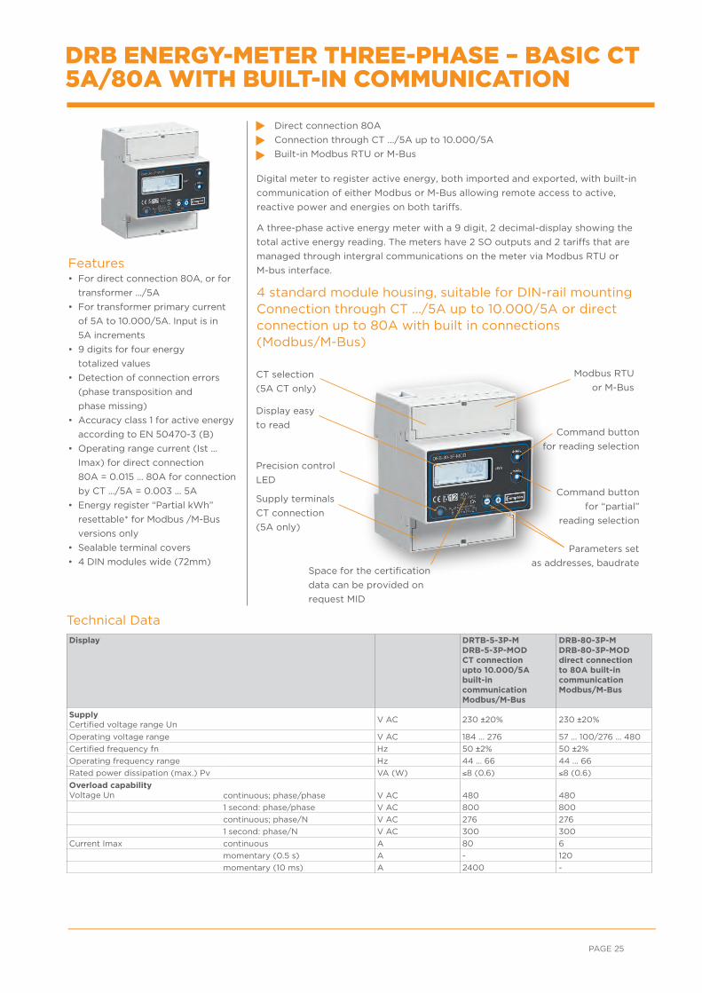
Modbus RTU
or M-Bus
Parameters set
as addresses, baudrate Space for the certification
data can be provided on
request MID
CT selection
(5A CT only)
Precision control
LEDCommand button
for “partial”
reading selection
Command button
for reading selection
Display easy
to read
Supply terminals
CT connection
(5A only)
DRB ENERGY-METER THREE-PHASE – BASIC CT 5A/80A WITH BUILT-IN COMMUNICATION
Digital meter to register active energy, both imported and exported, with built-in
communication of either Modbus or M-Bus allowing remote access to active,
reactive power and energies on both tariffs.
A three-phase active energy meter with a 9 digit, 2 decimal-display showing the
total active energy reading. The meters have 2 SO outputs and 2 tariffs that are
managed through intergral communications on the meter via Modbus RTU or
M-bus interface.
4 standard module housing, suitable for DIN-rail mountingConnection through CT .../5A up to 10.000/5A or direct connection up to 80A with built in connections (Modbus/M-Bus)
Direct connection 80A
Connection through CT .../5A up to 10.000/5A
Built-in Modbus RTU or M-Bus
PAGE 25
Technical Data
Display DRTB-5-3P-M DRB-5-3P-MODCT connectionupto 10.000/5Abuilt-incommunicationModbus/M-Bus
DRB-80-3P-M DRB-80-3P-MOD direct connection to 80A built-in communication Modbus/M-Bus
Supply Certified voltage range Un
V AC 230 ±20% 230 ±20%
Operating voltage range V AC 184 ... 276 57 ... 100/276 ... 480
Certified frequency fn Hz 50 ±2% 50 ±2%
Operating frequency range Hz 44 ... 66 44 ... 66
Rated power dissipation (max.) Pv VA (W) ≤8 (0.6) ≤8 (0.6)
Overload capabilityVoltage Un continuous; phase/phase V AC 480 480
1 second: phase/phase V AC 800 800
continuous; phase/N V AC 276 276
1 second: phase/N V AC 300 300
Current Imax continuous A 80 6
momentary (0.5 s) A - 120
momentary (10 ms) A 2400 -
Features• For direct connection 80A, or for
transformer .../5A
• For transformer primary current
of 5A to 10.000/5A. Input is in
5A increments
• 9 digits for four energy
totalized values
• Detection of connection errors
(phase transposition and
phase missing)
• Accuracy class 1 for active energy
according to EN 50470-3 (B)
• Operating range current (Ist ...
Imax) for direct connection
80A = 0.015 ... 80A for connection
by CT .../5A = 0.003 ... 5A
• Energy register “Partial kWh”
resettable* for Modbus /M-Bus
versions only
• Sealable terminal covers
• 4 DIN modules wide (72mm)
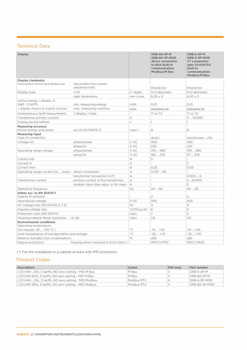
Technical Data
Display DRB-80-3P-M DRB-80-3P-MOD direct connection to 80A built-in communication Modbus/M-Bus
DRB-5-3P-MDRB-5-3P-MODCT connectionupto 10.000/5Abuilt-incommunicationModbus/M-Bus
Display (readouts)Connection errors and phase out
discernible from phase- sequence indic. - PHASE Err PHASE Err
Display type LCD n° digits 9 (2 decimals) 9 (2 decimals)
digit dimensions mm x mm 6.00 x 3 6.00 x 3
Active energy: 1 display, 9 digit - 2 tariffs min. measuring energy kWh 0.01 0.01
+ display import or export (arrow) max. measuring overflow kWh 9999999.99 9999999.99
Instantaneous tariff measurement 1 display, 1-digit - T1 or T2 T1 or T2
Transformer primary current A - 5 ... 10.000
Display period refresh s 1 1
Measuring accuracyActive energy and power acc.to EN 50470-3 class 1 B B
Measuring inputType of connection direct transformer .../5A
Voltage Un phase/phase V AC 400 400
phase/N V AC 230 230
Operating range voltage phase/phase V AC 319 ... 480 319 ... 480
phase/N V AC 184 ... 276 57 ... 276
Current Iref A 5 -
Current In A - 5
Current Imin A 0.25 0.05
Operating range current (Ist ... Imax) direct connection A 0.015 ... 80 -
transformer connection (CT) A - 0.003 ... 6
Transformer current primary current of the transformer A - 5 ...10.000
smallest input step adjus. in 5A steps A - 5
Operating frequency Hz 44 ... 66 44 ... 66
Safety acc. to EN 50470-1Degree of pollution - 2 2
Operational voltage V AC 300 300
AC voltage test (EN 50470-3, 7.2) kV 4 4
Impulse voltage test 1.2/50 μs-kV 6 6
Protection class (EN 50470) class II II
Housing material flame resistance UL 94 class V0 V0
Environmental conditionsOperating temperature
(on request -25 ... +55 °C ) °C -10 ... +55 -10 ... +55
Limit temperature of transportation and storage °C -25 ... +70 -25 ... +70
Relative humidity (not condensation) % ≤80 ≤80
Degree protection housing when mounted in front (term.) - IP51(*)/IP20 IP51(*)/IP20
ENERGY /// CROMPTON-INSTRUMENTS.COM/KWH.HTML
Description Comm DIN mod. Part number
LCD kWh ../5A, 2 tariffs, NO zero setting - MID M-Bus M-Bus 4 DRB-5-3P-M
LCD kWh 80A, 2 tariffs, NO zero setting - MID M-Bus M-Bus 4 DRB-80-3P-M
LCD kWh ../5A, 2 tariffs, NO zero setting - MID Modbus Modbus RTU 4 DRB-5-3P-MOD
LCD kWh 80A, 2 tariffs, NO zero setting - MID Modbus Modbus RTU 4 DRB-80-3P-MOD
Product Codes
(*) For the installation in a cabinet at least with IP51 protection.

Wire N needs to be connected to the meter
Wire N needs to be connected to the meter
An 80A fuse is recommended for the
line protection.
A 6A fuse is recommended for the
line protection. Current transformers
must not be operated with open
terminals as dangerous high voltages
might occur and may result in
personal injuries and property
damage. Transformers are exposed
to thermal overload.
DimensionsDRB-80-3P-MOD
DRB-80-3P-M
DimensionsDRB-5-3P-MOD
DRB-5-3P-M
Circuit diagramsDRB-80-3P-MOD
DRB-80-3P-M
Circuit diagramsDRB-5-3P-MOD
DRB-5-3P-M
Panel fixing optionDR-96-3MOD-GRAY
DR-96-4MOD-GRAY
PAGE 27

Features• Internal Data Storage (2 GB)
• Network connection through RJ45
• Software included within the
product (LAN Server)
• Suitable for single-phase and
three-phase instruments on
RS485 network
• Modbus TCP/IP data protocol
• HTTP support via internet browser
• Static or DHCP based addressing
• Dynamic DNS to mountain a host
name, accessible on the internet,
without the need for a static IP
• Internal RTC with NTP protocol
support
• One LAN server for 31 single or
three-phase devices
• Internet browser user interface
• 4 DIN modules wide (72 mm)
NETWORK CONVERTER FOR ENERGY METERS
OverviewThe product collects data from different energy meters on a Modbus (RS-485) network
and makes this data available in a variety of network compatible forms.
• Internal data storage
• Access via Modbus TCP/IP network
• LAN Server with internal software
ConnectivityEach energy meter in the DRM and DRB range has a unique (internal) serial number.
This allows the DRB-LAN-RS485 product to recognise different products on the
RS485 network and access the measured parameters of these products.
Date and time stampThe DRB-LAN-RS485 product has an internal real time clock (RTC) to support event
recording. The product is able to also support date/time synchronisation through
NTP protocol.
Data StorageAn internal micro SD-card can store 2 Gigabytes of data from the RS485 network.
The duration of data storage depends on three factors
• Number of parameters recorded from each device
• Number of devices on the RS485 network
• The time interval of each parameter
• Example: if all 50 parameters from 5 meters a stored every minute, the 2GB memory capacity is about two years.
Modbus TCP/IP NetworkThe DRB-LAN-RS485 product can be connected to any 100Mbit LAN network via the
RJ45 socket.
LAN ServerThe software within the DRB-LAN-RS485 product supports multiple languages and
can be accessed using any internet browser connected on the network
LAN Server SecurityAccess to the LAN Server can only be made with a valid Username and Password.
The product supports two levels of security.
• User - View devices and parameters
• Administrator - Network and device settings
LAN Server Functions• Verification and selection of every device which is connected to LAN-Server via the
RS485 network.
• View and selection of storage parameters, for each device which is connected to the
RS485 network.
• Selection of data storage time interval
• Configuration of LAN network and system parameters (for administrators only)
• User management (for administrator only)
Selection and ordering dataData concentrator - 4 modules DIN
ENERGY /// CROMPTON-INSTRUMENTS.COM/KWH.HTML
Description Part Number
LAN Network converter DRB-LAN-RS485

Technical data
Data in compliance with IEE 802.3 AS, IEC 60950-1, EN 61000-6-2, EN 61000-4-2
Unit DRB-LAN-RS485
General characteristicsHousing DIN 43880 4 modules
Mounting EN 60715 DIN rail (35mm)
Depth mm 70
Weight g 168
Stored values (internal) years 10
Auxiliary supplyAuxiliary voltage rating Un VAC 230
Auxiliary power rating VA ≤10
Auxiliary voltage range Un VAC 184 ... 276
Frequency range Hz 44 ... 66
Operating featuresSystem start
-
Aatomatic at connect of auxillary power
LAN server data addressing - by means of its server IP
Data transfer speed Mbit/s ≤100
LAN Interface ConnectionHardware interface
-
RJ 45 connector
Software protocol - TCP/IP - HTTP - Modbus/TCP FTP - SNTP - DHCP - DNS DynDNS - SNMP DynDNS - SNMP
Instruments Bus interfaceHardware interface (Modbus-RS485) n° termin. 3 A, B, Cable Shield
Cable type - shielded twisted pair
conductor cross section mm2 �≤2 x 0.2 or 2 x 24 AWG
conductor capacitance pF/m ≤50
impedance ohm 120
Cable length m ≤100
Directly connected instruments n° 31
Communications protocol - Modbus RTU and Ascii
SafetyDegree pollution - 2
Overvoltage category - II
Working voltage V 300
Clearance mm 4.0
Creepage distance in equipment mm 4.5
Test voltage impulse (1,2/50 s) peak value Kv 4
50 Hz 1 min Kv 4
Housing material flame resistance class UL 94V0
Connection terminalsType cage POZIDRIV
Terminal capacity solid wire min. (max)stranded wire with sleeve min. (max)
mm2
mm2
0.75 (6) 0.75 (4)
Environmental conditions (storage)Temperature range °C -25 ... +70
Environmental conditions (operating)Temperature range °C -10 ... +55
Altitude (max.) meters ≤2000
Humidity yearly average, not condensing
on 30 days per year (not condensing)
- ≤75%
- ≤95%
IP rating - IP20
PAGE 29
ENERGY /// CROMPTON-INSTRUMENTS.COM/KWH.HTML
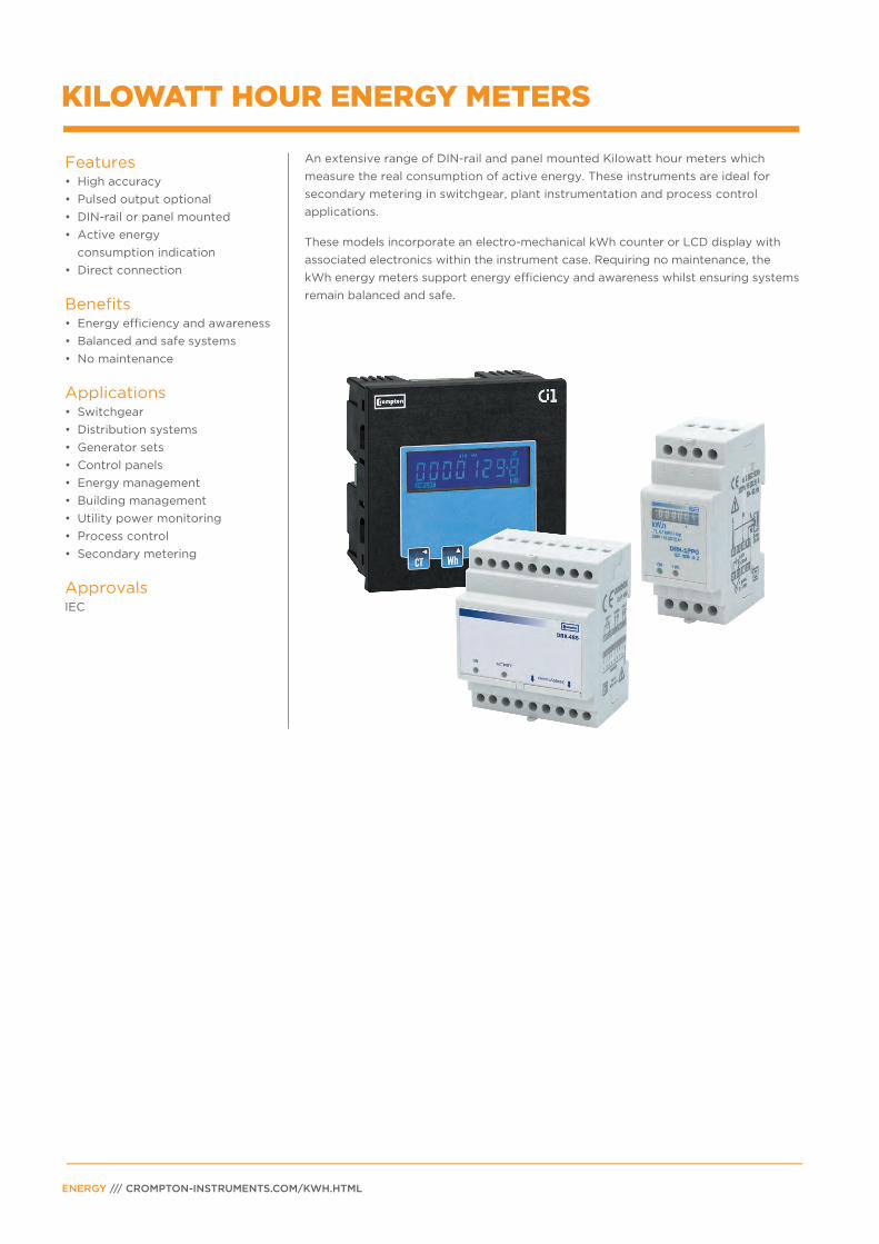
An extensive range of DIN-rail and panel mounted Kilowatt hour meters which
measure the real consumption of active energy. These instruments are ideal for
secondary metering in switchgear, plant instrumentation and process control
applications.
These models incorporate an electro-mechanical kWh counter or LCD display with
associated electronics within the instrument case. Requiring no maintenance, the
kWh energy meters support energy efficiency and awareness whilst ensuring systems
remain balanced and safe.
KILOWATT HOUR ENERGY METERS
Features• High accuracy
• Pulsed output optional
• DIN-rail or panel mounted
• Active energy
consumption indication
• Direct connection
Benefits• Energy efficiency and awareness
• Balanced and safe systems
• No maintenance
Applications• Switchgear
• Distribution systems
• Generator sets
• Control panels
• Energy management
• Building management
• Utility power monitoring
• Process control
• Secondary metering
ApprovalsIEC

IMPORT EXPORT
SET3 ~/21 N
MVArh MWhkVArh kWh
1%
53.00
77.50
Features• Backlit LCD screen
• Bezel depth 6.1mm
• Plug-in output modules
• Programmable CT ratio
• User programmable system configuration
• Phase diagnostic indication
• System running indication
• Removable energy threshold (1%)
Benefits• Cost effective
• Intuitive navigation
• Easy ‘clip-in’ panel mounting
StandardsIEC 61326IEC 61010-1IEC 62053-21RoHS Compliant
Parameters
The Integra Ci1 energy meter is specially designed and developed as a cost affected
watt hour and VAr hour meter to complement the current Crompton Instruments Ci
meter series. The Integra Ci1 self-contained 96mm DIN panel mounted Watt hour,
VAr hour meter measures the real consumption of active and reactive energy to Class
1.0 accuracy.
Programmable functionsIntegra Ci1 kWh meter provides simple programming to suit single-phase, three-
phase three-wire and three-phase four-wire un-balanced system configurations,
CT ratio settings and configuration of selected communication options. To prevent
unauthorised access to the product configuration settings, all set-up screens offer
password protection.
Specifications
Ordering Codes
PANEL MOUNTED INTEGRA CI1 ENERGY METER
Input
Nominal input voltage 100-289V AC L-N (173-500V AC L-L)
Max. continuous input 120% of nominal
overload voltage
Max. short duration input voltage 2 x range maximum (1 second application repeated 5 times at 5 min intervals)
Nominal input voltage burden < 0.2VA per phase
Nominal input current 5A AC rms
Max. continuous input overload current 120% of nominal
Max. short duration input current 10 x range maximum (1 second applicationrepeated 5 times at 5 min intervals)
Frequency 45-66Hz
Auxiliary
Operating range 110-400V AC nominal +/- 10% (99-440V AC absolute limits) or 120-350V DC +/- 20% (96-420V DC absolute limits)
Auxiliary burden 5 VA (Max)
Accuracy
Active energy (Wh) Class 1 (IEC 62053-21)
Reactive energy (VArh) +/- 1% of range
Display
LCD 8 character backlit counter (#######.#)After the maximum reading is reached thedigits will return to zero
Output modules (optional)
Pulsed output relays 1 per module(2 modules fitted per Ci1)
Contact rating 50mA max at 250V AC
Type Solid state relay
RS485 output module 1 RS-485 communication module(maximum of 1 module fitted per Ci1)
Type 2-wire half duplex
Baud rate 2400, 4800, 9600, 19200, 38400
Enclosure
Enclosure style DIN 96 panel mount
Dimensions 96x96x64.1mm (depth behind panel without module 58mm, with module 82.5mm)
Panel cut-out 92x92mm
Panel thickness 1-5mm
Front protection rating IP52
Description Part Number
Integra Ci1 base unit CI1-01
Options
Pulsed output CI-PUL-01
Modbus® RS485 output CI-MOD-01
Accessories
IP65 protective cover 3 G365 02
IP54 panel gasket 3 C345 01
Button Screen Parameters
CT 1 CT Ratio
Wh 2 3
IMPORT Wh EXPORT Wh
VArh 4 5
IMPORT VArh EXPORT VArh
TEST 6 Phase sequence diagnostic
PAGE 31
DRK-3PCT Three-phase
CT connected 5A(*) three-wire system
DRK-3PCT Three-phase
CT connected 5A(*) four-wire system
Pulse
Output
Ordering Codes
Dimensions and Connections
Description Part Number
3-phase 230V -CT connected 5A, pulsed output, 3 or 4-wire DRK-3PCT-415
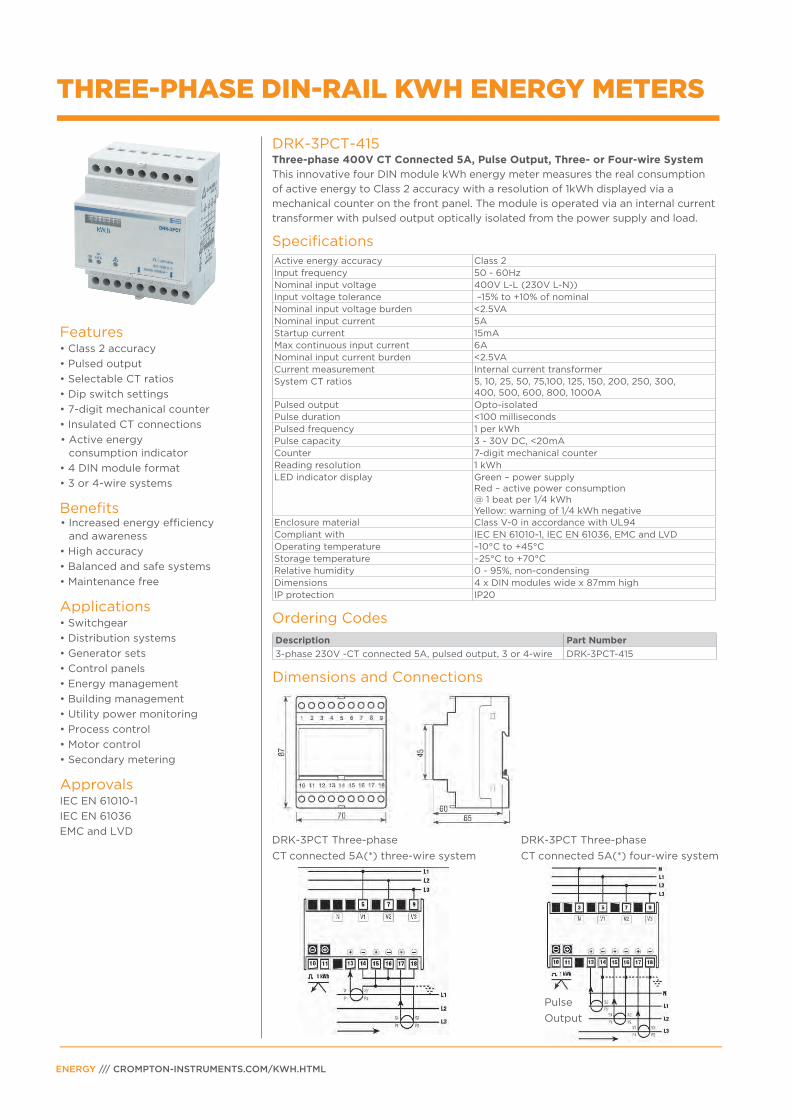
Active energy accuracy Class 2Input frequency 50 - 60HzNominal input voltage 400V L-L (230V L-N))Input voltage tolerance –15% to +10% of nominalNominal input voltage burden <2.5VANominal input current 5AStartup current 15mAMax continuous input current 6ANominal input current burden <2.5VACurrent measurement Internal current transformerSystem CT ratios 5, 10, 25, 50, 75,100, 125, 150, 200, 250, 300,
400, 500, 600, 800, 1000APulsed output Opto-isolatedPulse duration <100 millisecondsPulsed frequency 1 per kWhPulse capacity 3 - 30V DC, <20mACounter 7-digit mechanical counterReading resolution 1 kWhLED indicator display Green – power supply
Red – active power consumption@ 1 beat per 1/4 kWh Yellow: warning of 1/4 kWh negative
Enclosure material Class V-0 in accordance with UL94Compliant with IEC EN 61010-1, IEC EN 61036, EMC and LVDOperating temperature –10°C to +45°CStorage temperature –25°C to +70°CRelative humidity 0 - 95%, non-condensingDimensions 4 x DIN modules wide x 87mm highIP protection IP20
DRK-3PCT-415Three-phase 400V CT Connected 5A, Pulse Output, Three- or Four-wire System This innovative four DIN module kWh energy meter measures the real consumption
of active energy to Class 2 accuracy with a resolution of 1kWh displayed via a
mechanical counter on the front panel. The module is operated via an internal current
transformer with pulsed output optically isolated from the power supply and load.
Specifications
Features• Class 2 accuracy
• Pulsed output
• Selectable CT ratios
• Dip switch settings
• 7-digit mechanical counter
• Insulated CT connections
• Active energy consumption indicator
• 4 DIN module format
• 3 or 4-wire systems
Benefits• Increased energy efficiency
and awareness
• High accuracy
• Balanced and safe systems
• Maintenance free
Applications• Switchgear
• Distribution systems
• Generator sets
• Control panels
• Energy management
• Building management
• Utility power monitoring
• Process control
• Motor control
• Secondary metering
ApprovalsIEC EN 61010-1
IEC EN 61036
EMC and LVD
THREE-PHASE DIN-RAIL KWH ENERGY METERS
ENERGY /// CROMPTON-INSTRUMENTS.COM/KWH.HTML
Ordering Codes
Dimensions and Connections
Description Part Number
Remote kWh energy consumption monitoring device DRK-485-230
Input frequency 50 - 60Hz
Nominal input voltage 230V AC
Input voltage tolerance –15% to +10% of nominal
Nominal input voltage burden 2VA
Digital communications RS485 interface Modbus® protocol
Band handling Dual charge
Baud rate 9600 bits per second
Transmission mode ASCII
Error detection method Longitudinal redundancy check
Max number of contactors Up to 8 input signals(1 and 3-phase)
Pulse input duration <100 milliseconds
LED indicator display Green – power supplyRed – data transit via RS485
Enclosure material Class V-0 in accordance with UL94
Compliant with IEC EN 61010-1, IEC EN 50081-1, IEC EN 50082-1, EMC and LVD
Operating temperature –10°C to +45°C
Storage temperature –25°C to +70°C
Relative humidity 0 – 95%, non-condensing
Dimensions 4 x DIN modules wide x 87mm high
IP protection IP41 to front, IP20 to rear
Operating temperature –10°C to +45°C
Storage temperature –25°C to +70°C
Relative humidity 0 - 95%, non-condensing
Dimensions 4 x DIN modules wide x 87mm high
IP protection IP20
PAGE 33
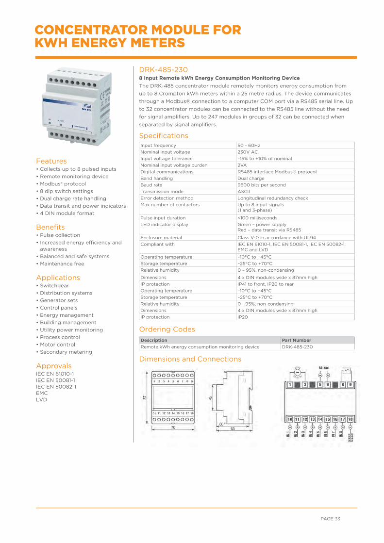
DRK-485-2308 Input Remote kWh Energy Consumption Monitoring Device
The DRK-485 concentrator module remotely monitors energy consumption from
up to 8 Crompton kWh meters within a 25 metre radius. The device communicates
through a Modbus® connection to a computer COM port via a RS485 serial line. Up
to 32 concentrator modules can be connected to the RS485 line without the need
for signal amplifiers. Up to 247 modules in groups of 32 can be connected when
separated by signal amplifiers.
Specifications
Features• Collects up to 8 pulsed inputs
• Remote monitoring device
• Modbus® protocol
• 8 dip switch settings
• Dual charge rate handling
• Data transit and power indicators
• 4 DIN module format
Benefits• Pulse collection
• Increased energy efficiency and awareness
• Balanced and safe systems
• Maintenance free
Applications• Switchgear
• Distribution systems
• Generator sets
• Control panels
• Energy management
• Building management
• Utility power monitoring
• Process control
• Motor control
• Secondary metering
ApprovalsIEC EN 61010-1 IEC EN 50081-1 IEC EN 50082-1 EMC LVD
CONCENTRATOR MODULE FOR KWH ENERGY METERS
65mm53.7mm
87m
m
Features• Class 1 accuracy
• Direct connected 63A
• Pulsed output (Opto)
• LCD display
• Non-zeroing total counter
• Active energy consumption indication
• 3 Din module format
Benefits• Energy efficiency and awareness
• High accuracy
• Balanced and safe systems
• No maintenance
Applications• Switchgear
• Distribution systems
• Generator sets
• Control panels
• Energy management
• Building management
• Utility power monitoring
• Process control
• Secondary metering
ApprovalsIEC EN62052-11
IEC EN62053-21
EMC and LVD
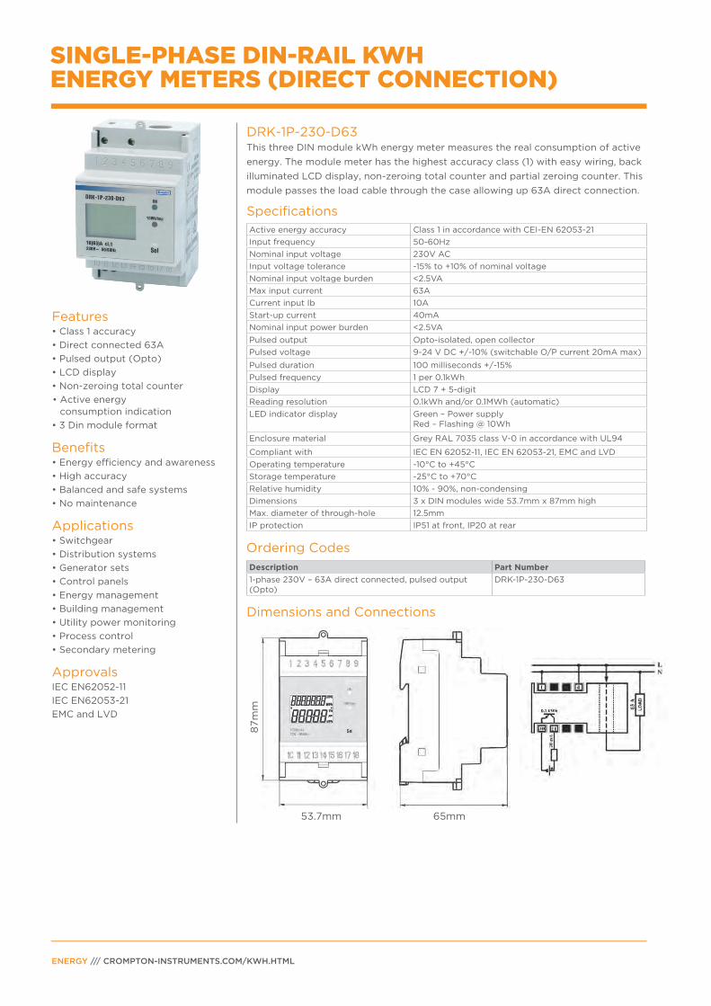
DRK-1P-230-D63This three DIN module kWh energy meter measures the real consumption of active
energy. The module meter has the highest accuracy class (1) with easy wiring, back
illuminated LCD display, non-zeroing total counter and partial zeroing counter. This
module passes the load cable through the case allowing up 63A direct connection.
Specifications
Ordering Codes
SINGLE-PHASE DIN-RAIL KWH ENERGY METERS (DIRECT CONNECTION)
ENERGY /// CROMPTON-INSTRUMENTS.COM/KWH.HTML
Active energy accuracy Class 1 in accordance with CEI-EN 62053-21
Input frequency 50-60Hz
Nominal input voltage 230V AC
Input voltage tolerance -15% to +10% of nominal voltage
Nominal input voltage burden <2.5VA
Max input current 63A
Current input Ib 10A
Start-up current 40mA
Nominal input power burden <2.5VA
Pulsed output Opto-isolated, open collector
Pulsed voltage 9-24 V DC +/-10% (switchable O/P current 20mA max)
Pulsed duration 100 milliseconds +/-15%
Pulsed frequency 1 per 0.1kWh
Display LCD 7 + 5-digit
Reading resolution 0.1kWh and/or 0.1MWh (automatic)
LED indicator display Green – Power supplyRed – Flashing @ 10Wh
Enclosure material Grey RAL 7035 class V-0 in accordance with UL94
Compliant with IEC EN 62052-11, IEC EN 62053-21, EMC and LVD
Operating temperature -10°C to +45°C
Storage temperature -25°C to +70°C
Relative humidity 10% - 90%, non-condensing
Dimensions 3 x DIN modules wide 53.7mm x 87mm high
Max. diameter of through-hole 12.5mm
IP protection IP51 at front, IP20 at rear
Description Part Number
1-phase 230V – 63A direct connected, pulsed output (Opto)
DRK-1P-230-D63
Dimensions and Connections
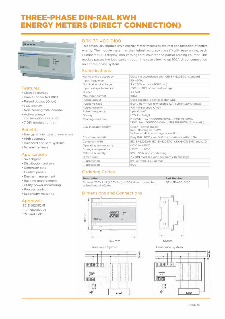
Three-wire System Four-wire System
125.7mm 65mm
87m
m
Ordering Codes
Dimensions and Connections
Description Part Number
3-phase 230V L-N (400V L-L) – 100A direct connected, pulsed output (Opto)
DRK-3P-400-D100
Active energy accuracy Class 1 in accordance with CEI-EN 62053-21 standard
Input frequency 50 - 60Hz
Nominal input voltage 3 x 230V ac L-N (400V L-L)
Input voltage tolerance -15% to +10% of nominal voltage
Burden < 2.5VA
Max input current 100A
Pulsed output Opto-isolated, open collector type
Pulsed voltage 9-24V dc +/-10% (switchable O/P current 20mA max)
Pulsed duration 100 milliseconds +/-15%
Pulsed frequency 1 per 0.1 kWh
Display LCD 7 + 5-digit
Reading resolution 0.1 KWh from 0000000.0KWh – 999999.9KWh 1 KWh from 1000000KWh to 9999999KWh (Automatic)
LED indicator display Green - power supply Red - flashing @ 10kWhYellow – indicates wrong connection
Enclosure material Grey RAL 7035 class V-0 in accordance with UL94
Compliant with IEC EN62052-11, IEC EN62053-21 (2003-03) EMC and LVD
Operating temperature -10°C to +45°C
Storage temperature -25°C to +70°C
Relative humidity 10% - 90%, non-condensing
Dimensions 7 x DIN modules wide 125.7mm x 87mm high
IP protection IP51 at front, IP20 at rear
IP protection IP20
PAGE 35
DRK-3P-400-D100 This seven DIN module kWh energy meter measures the real consumption of active
energy. The module meter has the highest accuracy class (1) with easy wiring, back
illuminated LCD display, non-zeroing total counter and partial zeroing counter. This
module passes the load cable through the case allowing up 100A direct connection
on a three-phase system.
Specifications
Features• Class 1 accuracy
• Direct connected 100A
• Pulsed output (Opto)
• LCD display
• Non-zeroing total counter
• Active energy consumption indication
• 7 DIN module format
Benefits• Energy efficiency and awareness
• High accuracy
• Balanced and safe systems
• No maintenance
Applications• Switchgear
• Distribution systems
• Generator sets
• Control panels
• Energy management
• Building management
• Utility power monitoring
• Process control
• Secondary metering
ApprovalsIEC EN62052-11
IEC EN62053-21
EMC and LVD
THREE-PHASE DIN-RAIL KWH ENERGY METERS (DIRECT CONNECTION)

ENERGY /// CROMPTON-INSTRUMENTS.COM/KWH.HTML
For email or phone, go to: crompton-instruments.com
FOR MORE INFORMATION: TE Technical Support CentresUK +44 1376 509 533
USA: +1 800 327 6996
Australia +61 1300 656 090
Singapore +65 6590 5151
Hong Kong: +852 2790 9609
crompton-instruments.com© 2015 TE Connectivity Ltd. family of companies. All Rights Reserved. EPP-2055-09/15
TE Connectivity and the TE connectivity (logo) are trademarks of the TE Connectivity Ltd. family of companies. Other logos, product and Company names mentioned herein may be trademarks of their respective owners. While TE has made every reasonable effort to ensure the accuracy of the information in this brochure, TE does not guarantee that it is error-free, nor does TE make any other representation, warranty or guarantee that the information is accurate, correct, reliable or current. TE reserves the right to make any adjustments to the information contained herein at any time without notice. TE expressly disclaims all implied warranties regarding the information contained herein, including, but not limited to, any implied warranties of merchantability or fitness for a particular purpose. The dimensions in this brochure are for reference purposes only and are subject to change without notice. Specifications are subject to change without notice. Consult TE for the latest dimensions and design specifications.
WHEREVER ELECTRICITY FLOWS, YOU’LL FIND TE ENERGY
crompton-instruments.com
Where panel mounting of the DIN rail devices is necessary a kit is available for
DIN96 cutouts.
Available in 3MOD and 4MOD the products can be easily panel mounted.
Part NumberDR-96-3MOD-GRAY
DR-96-4MOD-GRAY
PANEL MOUNTING OPTION KIT