(CRM) 8.0 Implementation Guide
72
- 1 - Radware’s AppDirector and Oracle Siebel Customer Relationship Management (CRM) 8.0 Implementation Guide Products: Radware AppDirector Software: AppDirector version 2.00.01 Platform: On-Demand Switch II XL Oracle Siebel 8
Transcript of (CRM) 8.0 Implementation Guide

- 1 -
Radware’s AppDirector and Oracle Siebel Customer Re lationship Management (CRM) 8.0 Implementation Guide
Products:
Radware AppDirector
Software: AppDirector version 2.00.01
Platform: On-Demand Switch II XL
Oracle Siebel 8
- 2 -
Table of Contents
Solution Overview.................................. .............................................................3
Siebel 8 Application Overview...................... .....................................................3 Client Tier.................................................................................................................................................. 3 Application Tier.........................................................................................................................................4 Database Tier............................................................................................................................................. 4 Gateway Name Server ............................................................................................................................... 4
Radware AppDirector Overview ....................... .................................................4
Deployment Notes ................................... ...........................................................5 SIEBEL 8 Load Balancing Application Notes .......................................................................................... 5 Siebel 8 Application Server load balancing rules ...................................................................................... 8
AppDirector and Siebel 8 Architecture .............. .............................................10 Diagram 1.0 – Siebel 8 and AppDirector Logical Topology................................................................... 10
Tests Conducted for Solution Validation ................................................................................................. 11
Radware’s AppDirector Configuration for Siebel 8... .....................................14 Diagram 2.0 – Siebel 8 and AppDirector Physical Topology.................................................................. 15
Primary AppDirector Configuration .................. ..............................................15 IP Configuration ...................................................................................................................................... 16 Farm Configuration ................................................................................................................................. 19 Create Layer 7 Policy .............................................................................................................................. 21 Create Cache Policy................................................................................................................................. 29 Create Compression Policy...................................................................................................................... 29 Create Layer 4 Policy .............................................................................................................................. 30 Configure NAT........................................................................................................................................ 33 Extended Farms ....................................................................................................................................... 36 Adding Servers to the Farm..................................................................................................................... 38 Health Monitoring ................................................................................................................................... 42
General Redundant Configuration Notes .............. .........................................48 Primary AppDirector VRRP Configuration............................................................................................. 50 Primary Virtual Routers........................................................................................................................... 50 Primary Associated IP Addresses ............................................................................................................ 52 Backup AppDirector VRRP Configuration ............................................................................................. 54 Backup Virtual Routers ........................................................................................................................... 55 Backup Associated IP Addresses............................................................................................................. 56
Appendix 1 – Primary AppDirector Configuration File ......................................................................... 60
Appendix 2 – Backup AppDirector Configuration File .......................................................................... 63
Appendix 3 – Insert Cookie - Auto Generated Configuration................................................................ 66
- 3 -
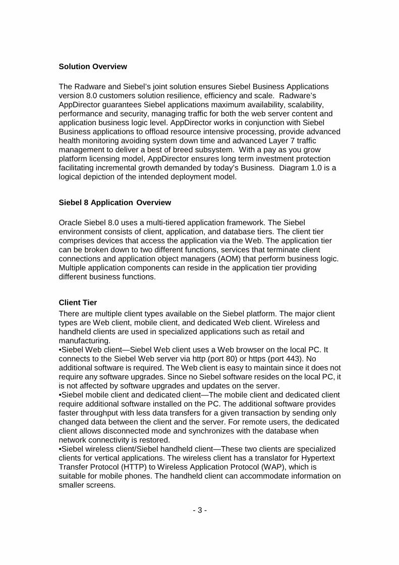
Solution Overview The Radware and Siebel’s joint solution ensures Siebel Business Applications version 8.0 customers solution resilience, efficiency and scale. Radware’s AppDirector guarantees Siebel applications maximum availability, scalability, performance and security, managing traffic for both the web server content and application business logic level. AppDirector works in conjunction with Siebel Business applications to offload resource intensive processing, provide advanced health monitoring avoiding system down time and advanced Layer 7 traffic management to deliver a best of breed subsystem. With a pay as you grow platform licensing model, AppDirector ensures long term investment protection facilitating incremental growth demanded by today’s Business. Diagram 1.0 is a logical depiction of the intended deployment model.
Siebel 8 Application Overview Oracle Siebel 8.0 uses a multi-tiered application framework. The Siebel environment consists of client, application, and database tiers. The client tier comprises devices that access the application via the Web. The application tier can be broken down to two different functions, services that terminate client connections and application object managers (AOM) that perform business logic. Multiple application components can reside in the application tier providing different business functions.
Client Tier There are multiple client types available on the Siebel platform. The major client types are Web client, mobile client, and dedicated Web client. Wireless and handheld clients are used in specialized applications such as retail and manufacturing. •Siebel Web client—Siebel Web client uses a Web browser on the local PC. It connects to the Siebel Web server via http (port 80) or https (port 443). No additional software is required. The Web client is easy to maintain since it does not require any software upgrades. Since no Siebel software resides on the local PC, it is not affected by software upgrades and updates on the server. •Siebel mobile client and dedicated client—The mobile client and dedicated client require additional software installed on the PC. The additional software provides faster throughput with less data transfers for a given transaction by sending only changed data between the client and the server. For remote users, the dedicated client allows disconnected mode and synchronizes with the database when network connectivity is restored. •Siebel wireless client/Siebel handheld client—These two clients are specialized clients for vertical applications. The wireless client has a translator for Hypertext Transfer Protocol (HTTP) to Wireless Application Protocol (WAP), which is suitable for mobile phones. The handheld client can accommodate information on smaller screens.
- 4 -
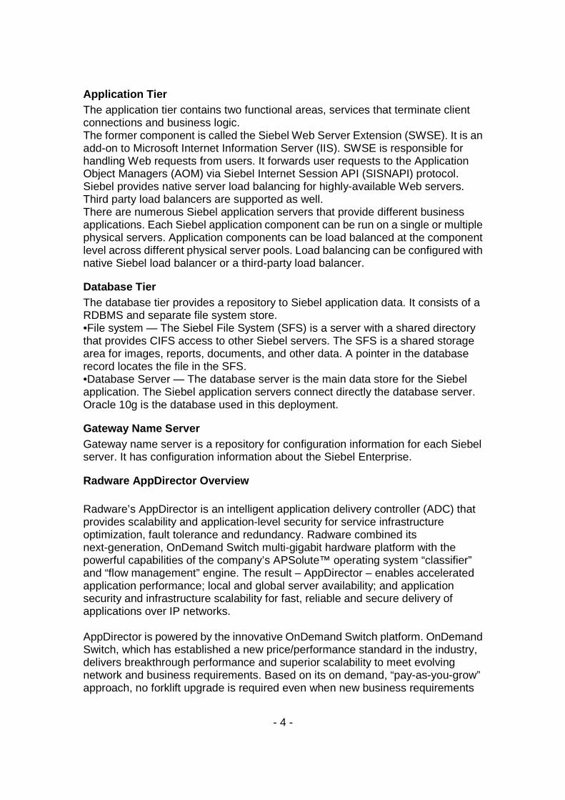
Application Tier The application tier contains two functional areas, services that terminate client connections and business logic. The former component is called the Siebel Web Server Extension (SWSE). It is an add-on to Microsoft Internet Information Server (IIS). SWSE is responsible for handling Web requests from users. It forwards user requests to the Application Object Managers (AOM) via Siebel Internet Session API (SISNAPI) protocol. Siebel provides native server load balancing for highly-available Web servers. Third party load balancers are supported as well. There are numerous Siebel application servers that provide different business applications. Each Siebel application component can be run on a single or multiple physical servers. Application components can be load balanced at the component level across different physical server pools. Load balancing can be configured with native Siebel load balancer or a third-party load balancer.
Database Tier The database tier provides a repository to Siebel application data. It consists of a RDBMS and separate file system store. •File system — The Siebel File System (SFS) is a server with a shared directory that provides CIFS access to other Siebel servers. The SFS is a shared storage area for images, reports, documents, and other data. A pointer in the database record locates the file in the SFS. •Database Server — The database server is the main data store for the Siebel application. The Siebel application servers connect directly the database server. Oracle 10g is the database used in this deployment.
Gateway Name Server Gateway name server is a repository for configuration information for each Siebel server. It has configuration information about the Siebel Enterprise.
Radware AppDirector Overview Radware’s AppDirector is an intelligent application delivery controller (ADC) that provides scalability and application-level security for service infrastructure optimization, fault tolerance and redundancy. Radware combined its next-generation, OnDemand Switch multi-gigabit hardware platform with the powerful capabilities of the company’s APSolute™ operating system “classifier” and “flow management” engine. The result – AppDirector – enables accelerated application performance; local and global server availability; and application security and infrastructure scalability for fast, reliable and secure delivery of applications over IP networks. AppDirector is powered by the innovative OnDemand Switch platform. OnDemand Switch, which has established a new price/performance standard in the industry, delivers breakthrough performance and superior scalability to meet evolving network and business requirements. Based on its on demand, “pay-as-you-grow” approach, no forklift upgrade is required even when new business requirements
- 5 -
arise. This helps companies guarantee short-term and long-term savings on CAPEX and OPEX for full investment protection. Radware’s OnDemand Switch enables customers to pay for the exact capacity currently required, while allowing them to scale their ADC throughput capacity and add advanced application-aware services or application acceleration services on demand to meet new or changing application and infrastructure needs. And it does it without compromising on performance. AppDirector lets you get the most out of your service investments by maximizing the utilization of service infrastructure resources and enabling seamless consolidation and high scalability. AppDirector’s throughput licensing options allows pay as you grow investment protection. Make your network adaptive and more responsive to your dynamic services and business needs with AppDirector’s fully integrated traffic classification and flow management, health monitoring and failure bypassing, traffic redirection, bandwidth management, intrusion prevention and DoS protection.
For more information, please visit: http://www.radware.com/
Deployment Notes
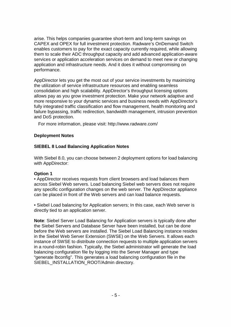
SIEBEL 8 Load Balancing Application Notes With Siebel 8.0, you can choose between 2 deployment options for load balancing with AppDirector: Option 1 • AppDirector receives requests from client browsers and load balances them across Siebel Web servers. Load balancing Siebel web servers does not require any specific configuration changes on the web server. The AppDirector appliance can be placed in front of the Web servers and can load balance requests. • Siebel Load balancing for Application servers; In this case, each Web server is directly tied to an application server. Note : Siebel Server Load Balancing for Application servers is typically done after the Siebel Servers and Database Server have been installed, but can be done before the Web servers are installed. The Siebel Load Balancing instance resides in the Siebel Web Server Extension (SWSE) on the Web Servers. It allows each instance of SWSE to distribute connection requests to multiple application servers in a round-robin fashion. Typically, the Siebel administrator will generate the load balancing configuration file by logging into the Server Manager and type “generate lbconfig”. This generates a load balancing configuration file in the SIEBEL_INSTALLATION_ROOT/Admin directory.
- 6 -
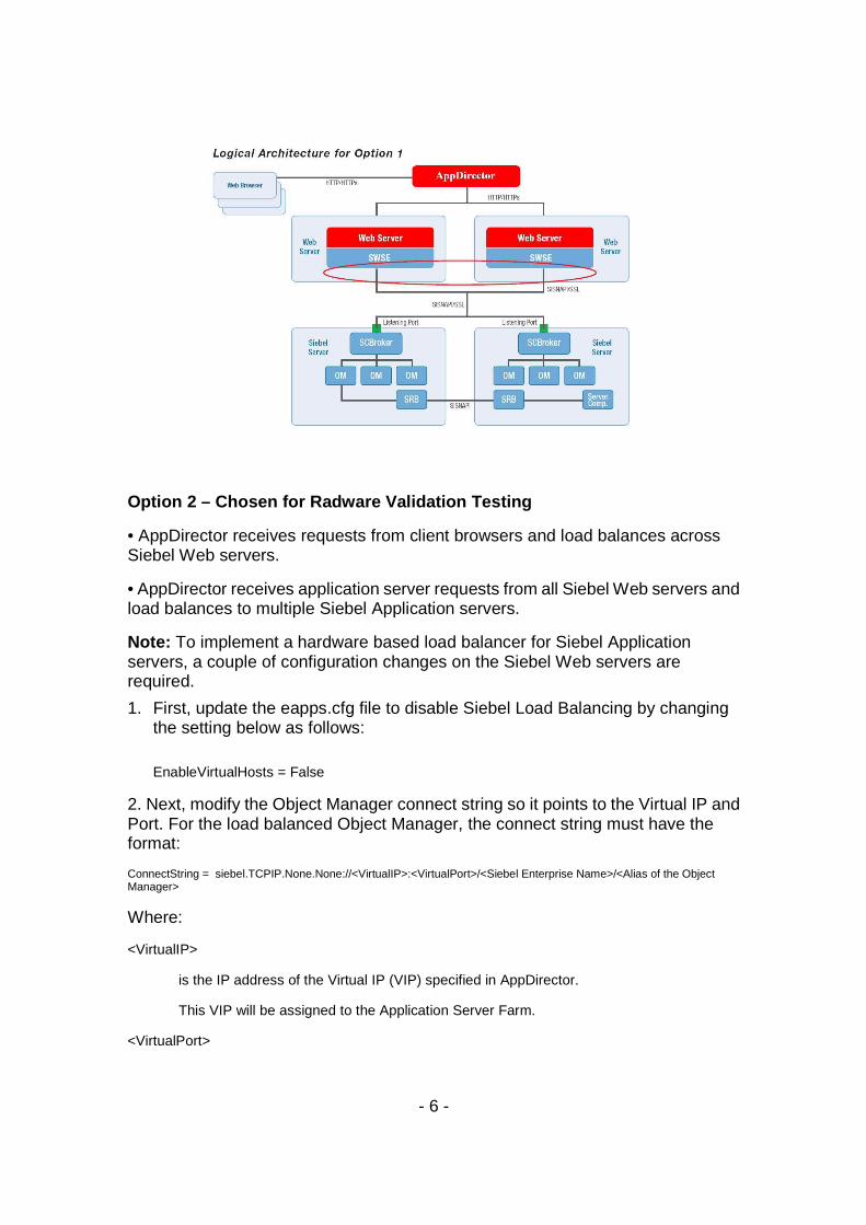
Option 2 – Chosen for Radware Validation Testing
• AppDirector receives requests from client browsers and load balances across Siebel Web servers.
• AppDirector receives application server requests from all Siebel Web servers and load balances to multiple Siebel Application servers.
Note: To implement a hardware based load balancer for Siebel Application servers, a couple of configuration changes on the Siebel Web servers are required.
1. First, update the eapps.cfg file to disable Siebel Load Balancing by changing the setting below as follows:
EnableVirtualHosts = False
2. Next, modify the Object Manager connect string so it points to the Virtual IP and Port. For the load balanced Object Manager, the connect string must have the format:
ConnectString = siebel.TCPIP.None.None://<VirtualIP>:<VirtualPort>/<Siebel Enterprise Name>/<Alias of the Object Manager>
Where:
<VirtualIP>
is the IP address of the Virtual IP (VIP) specified in AppDirector.
This VIP will be assigned to the Application Server Farm.
<VirtualPort>
- 7 -
is the Port Number, or Service defined in the Layer 4 policy VIP definition.
The default port is 2321.
<Siebel Enterprise Name>
is the name of the Siebel Enterprise in which the load balanced Siebel Servers reside.
<Alias of the Object Manager>
is the alias of the Load Balanced Object Manager.
Example eapps.cfg:
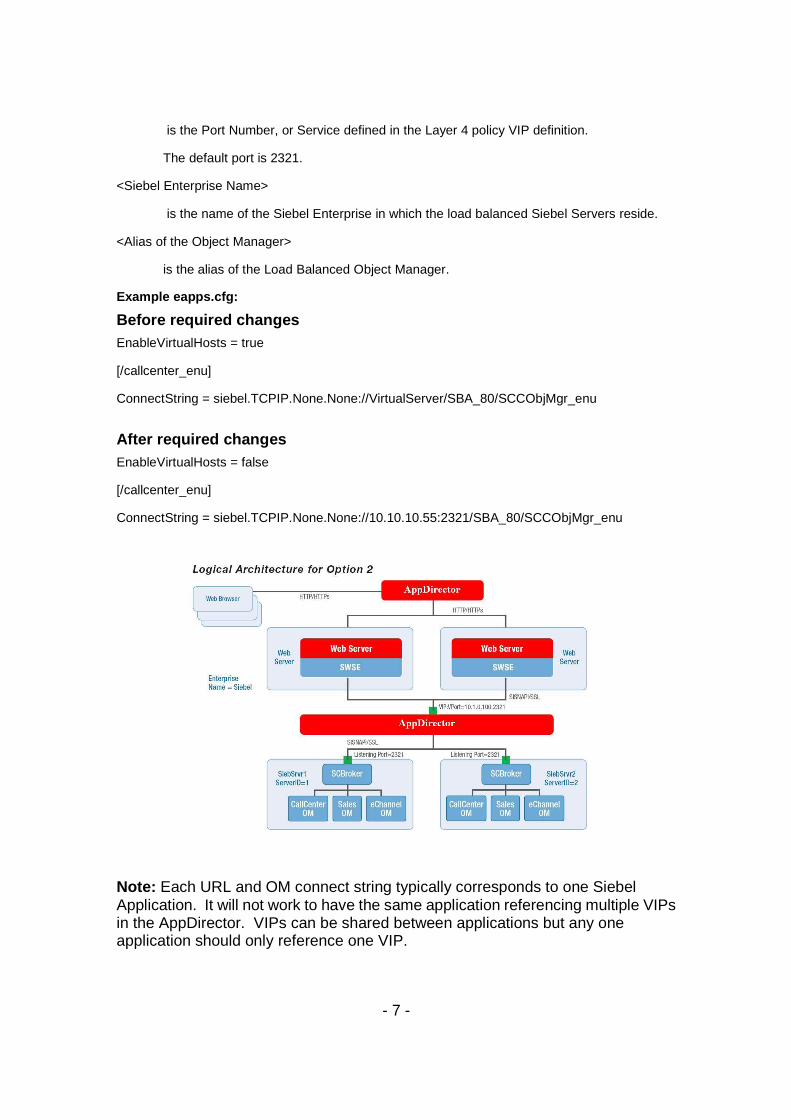
Before required changes EnableVirtualHosts = true
[/callcenter_enu]
ConnectString = siebel.TCPIP.None.None://VirtualServer/SBA_80/SCCObjMgr_enu
After required changes EnableVirtualHosts = false
[/callcenter_enu]
ConnectString = siebel.TCPIP.None.None://10.10.10.55:2321/SBA_80/SCCObjMgr_enu
Note: Each URL and OM connect string typically corresponds to one Siebel Application. It will not work to have the same application referencing multiple VIPs in the AppDirector. VIPs can be shared between applications but any one application should only reference one VIP.
- 8 -
Siebel 8 Application Server load balancing rules Developing the load balancing rules for AppDirector to direct traffic to the Siebel Application Tier requires an understanding of the “lbconfig” file generated for Siebel local load balancing by the SWSE. There are three rules that need to be defined:
1. The first time a request is established for a new connection. 2. When the server needs to reconnect back to the same server after a
disconnect occurs 3. When the Siebel Broker detects that no AOM is available that the
request should be Round Robin load balanced to the next broker to handle the request.
Here is a sample section of the “lbconfig” file ______________________________________________________________ # This is the load balance configuration file generated by the Siebel srvrmgr "generate lbconfig" command.
# It contains two sections. Section one contains load balancing rules to be used by Siebel session manager.
# Section two is intended for 3rd party load balancers. Before modifying the content of this file please
# read the chapter on SWSE configuration in the Siebel Bookshelf.
#Section one -- Session Manager Rules:
VirtualServer=1:siebelrw:2321;5:siebelrw1:2321;
******************************
#Section two -- 3rd Party Load Balancer Rules
/SBA_80/SCCObjMgr_enu=siebelrw1:2321;siebelrw:2321;
#Server Rules:
*/!1.*=siebelrw:2321;
*/!5.*=siebelrw1:2321;
#Round Robin Rules:
/SBA_80/SCCObjMgr_enu/RR=siebelrw1:2321;siebelrw:2321;
______________________________________________________________
- 9 -
Explanation of the “lbconfig” file The first section identifies the Siebel application servers and the port the broker is listening on. VirtualServer=1:siebelrw:2321;5:siebelrw1:2321;
The string “1:siebelrw:2321;5:siebelrw1:2321” has the following meaning:
• 1 is assigning to the server siebelrw and 5 is assigning to the server siebelrw1 • siebelrw is the host name and translates to IP 10.10.10.53 and siebelrw1 to IP 10.10.10.50 • 2321 is the port that the Broker is listening on.
When the AppDirector reads the URL sent from the SWSE to determine what action to take when directing traffic to the Siebel Server requires the setup of three server farms:
• One containing siebelrw:2321;siebelrw1:2321, this will be used to load
balance The first time a request is established for a new connection and when a connecting is rejected by a Broker and the SWSE sends a request to the AppDirector to round robin the request to a new broker.
The next two farms are used when the server needs to reconnect back to the same server after a disconnection occurs, L7 URI persistence. This is a one to one mapping of the URI to a Farm containing a single server. • one containing siebelrw:2321 • one containing siebelrw1:2321
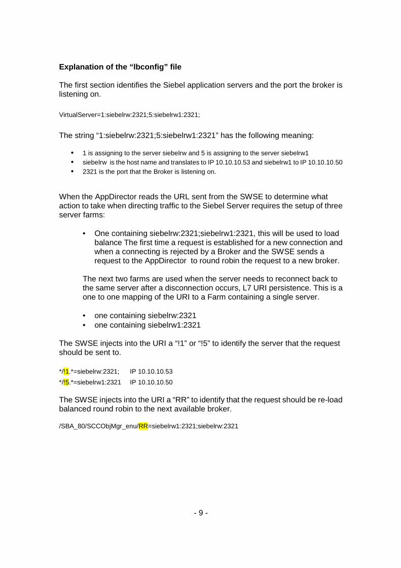
The SWSE injects into the URI a “!1” or “!5” to identify the server that the request should be sent to.
*/!1.*=siebelrw:2321; IP 10.10.10.53
*/!5.*=siebelrw1:2321 IP 10.10.10.50 The SWSE injects into the URI a “RR” to identify that the request should be re-load balanced round robin to the next available broker. /SBA_80/SCCObjMgr_enu/RR=siebelrw1:2321;siebelrw:2321
- 10 -
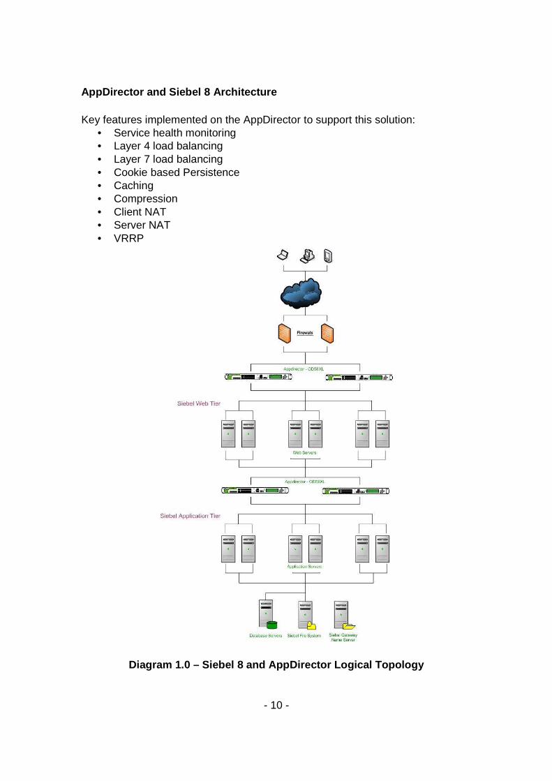
AppDirector and Siebel 8 Architecture Key features implemented on the AppDirector to support this solution:
• Service health monitoring • Layer 4 load balancing • Layer 7 load balancing • Cookie based Persistence • Caching • Compression • Client NAT • Server NAT • VRRP
Diagram 1.0 – Siebel 8 and AppDirector Logical Topo logy
- 11 -
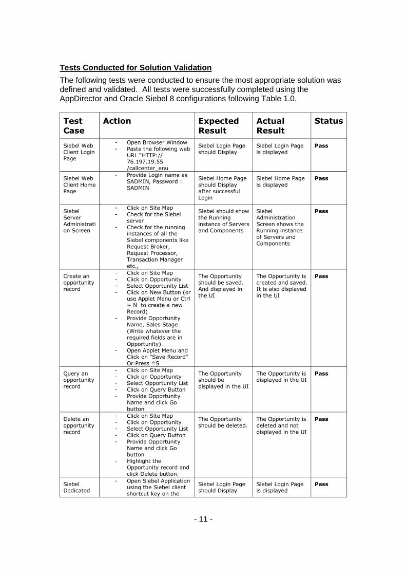
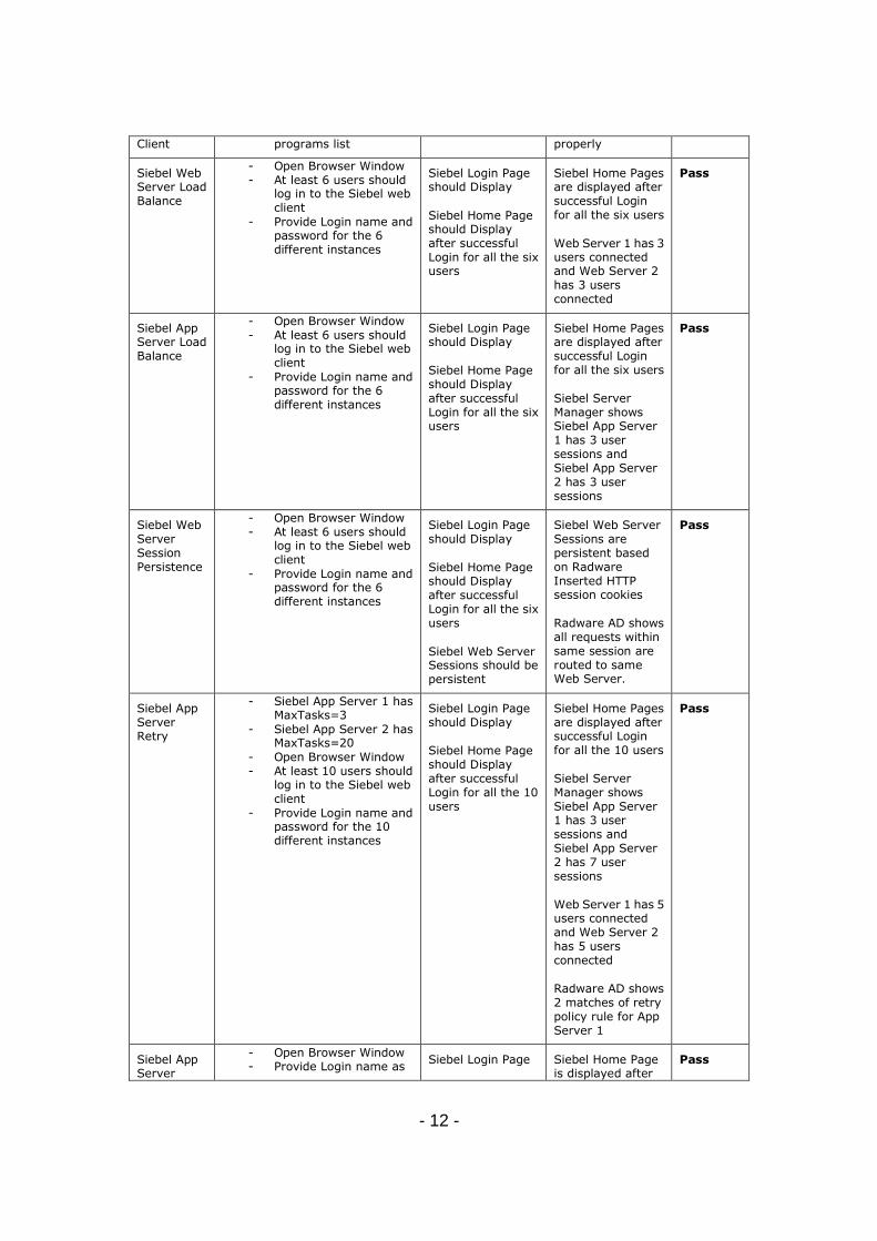
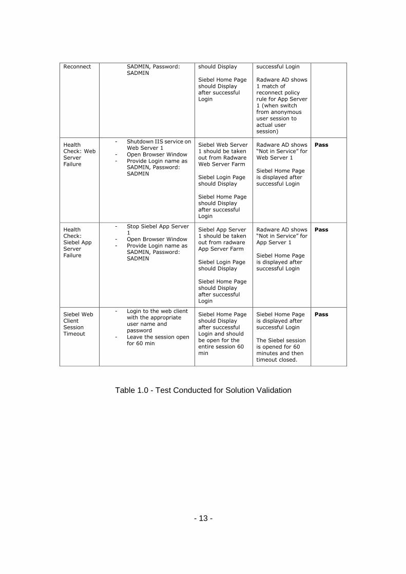
Tests Conducted for Solution Validation
The following tests were conducted to ensure the most appropriate solution was defined and validated. All tests were successfully completed using the AppDirector and Oracle Siebel 8 configurations following Table 1.0.
Test
Case
Action Expected
Result
Actual
Result
Status
Siebel Web Client Login Page
- Open Browser Window - Paste the following web
URL “HTTP:// 76.197.19.55 /callcenter_enu
Siebel Login Page should Display
Siebel Login Page is displayed
Pass
Siebel Web Client Home Page
- Provide Login name as SADMIN, Password : SADMIN
Siebel Home Page should Display after successful Login
Siebel Home Page is displayed
Pass
Siebel Server Administration Screen
- Click on Site Map - Check for the Siebel
server - Check for the running
instances of all the Siebel components like Request Broker, Request Processor, Transaction Manager etc.,
Siebel should show the Running instance of Servers and Components
Siebel Administration Screen shows the Running instance of Servers and Components
Pass
Create an opportunity record
- Click on Site Map - Click on Opportunity - Select Opportunity List - Click on New Button (or
use Applet Menu or Ctrl + N to create a new Record)
- Provide Opportunity Name, Sales Stage (Write whatever the required fields are in Opportunity)
- Open Applet Menu and Click on "Save Record" Or Press ^S
The Opportunity should be saved. And displayed in the UI
The Opportunity is created and saved. It is also displayed in the UI
Pass
Query an opportunity record
- Click on Site Map - Click on Opportunity - Select Opportunity List - Click on Query Button - Provide Opportunity
Name and click Go button
The Opportunity should be displayed in the UI
The Opportunity is displayed in the UI
Pass
Delete an opportunity record
- Click on Site Map - Click on Opportunity - Select Opportunity List - Click on Query Button - Provide Opportunity
Name and click Go button
- Highlight the Opportunity record and click Delete button.
The Opportunity should be deleted.
The Opportunity is deleted and not displayed in the UI
Pass
Siebel Dedicated
- Open Siebel Application using the Siebel client shortcut key on the
Siebel Login Page should Display
Siebel Login Page is displayed
Pass
- 12 -
Client programs list properly
Siebel Web Server Load Balance
- Open Browser Window - At least 6 users should
log in to the Siebel web client
- Provide Login name and password for the 6 different instances
Siebel Login Page should Display
Siebel Home Page should Display after successful Login for all the six users
Siebel Home Pages are displayed after successful Login for all the six users
Web Server 1 has 3 users connected and Web Server 2 has 3 users connected
Pass
Siebel App Server Load Balance
- Open Browser Window - At least 6 users should
log in to the Siebel web client
- Provide Login name and password for the 6 different instances
Siebel Login Page should Display
Siebel Home Page should Display after successful Login for all the six users
Siebel Home Pages are displayed after successful Login for all the six users
Siebel Server Manager shows Siebel App Server 1 has 3 user sessions and Siebel App Server 2 has 3 user sessions
Pass
Siebel Web Server Session Persistence
- Open Browser Window - At least 6 users should
log in to the Siebel web client
- Provide Login name and password for the 6 different instances
Siebel Login Page should Display
Siebel Home Page should Display after successful Login for all the six users
Siebel Web Server Sessions should be persistent
Siebel Web Server Sessions are persistent based on Radware Inserted HTTP session cookies
Radware AD shows all requests within same session are routed to same Web Server.
Pass
Siebel App Server Retry
- Siebel App Server 1 has MaxTasks=3
- Siebel App Server 2 has MaxTasks=20
- Open Browser Window - At least 10 users should
log in to the Siebel web client
- Provide Login name and password for the 10 different instances
Siebel Login Page should Display
Siebel Home Page should Display after successful Login for all the 10 users
Siebel Home Pages are displayed after successful Login for all the 10 users
Siebel Server Manager shows Siebel App Server 1 has 3 user sessions and Siebel App Server 2 has 7 user sessions
Web Server 1 has 5 users connected and Web Server 2 has 5 users connected
Radware AD shows 2 matches of retry policy rule for App Server 1
Pass
Siebel App Server
- Open Browser Window - Provide Login name as
Siebel Login Page Siebel Home Page is displayed after
Pass
- 13 -
Reconnect SADMIN, Password: SADMIN
should Display
Siebel Home Page should Display after successful Login
successful Login
Radware AD shows 1 match of reconnect policy rule for App Server 1 (when switch from anonymous user session to actual user session)
Health Check: Web Server Failure
- Shutdown IIS service on Web Server 1
- Open Browser Window - Provide Login name as
SADMIN, Password: SADMIN
Siebel Web Server 1 should be taken out from Radware Web Server Farm
Siebel Login Page should Display
Siebel Home Page should Display after successful Login
Radware AD shows “Not in Service” for Web Server 1
Siebel Home Page is displayed after successful Login
Pass
Health Check: Siebel App Server Failure
- Stop Siebel App Server 1
- Open Browser Window - Provide Login name as
SADMIN, Password: SADMIN
Siebel App Server 1 should be taken out from radware App Server Farm
Siebel Login Page should Display
Siebel Home Page should Display after successful Login
Radware AD shows “Not in Service” for App Server 1
Siebel Home Page is displayed after successful Login
Pass
Siebel Web Client Session Timeout
- Login to the web client with the appropriate user name and password
- Leave the session open for 60 min
Siebel Home Page should Display after successful Login and should be open for the entire session 60 min
Siebel Home Page is displayed after successful Login
The Siebel session is opened for 60 minutes and then timeout closed.
Pass
Table 1.0 - Test Conducted for Solution Validation
- 14 -
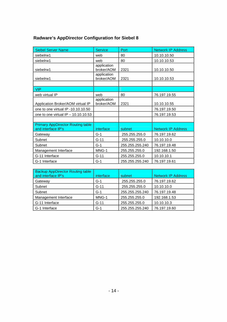
Radware’s AppDirector Configuration for Siebel 8 Siebel Server Name Service Port Network IP Address
siebelrw1 web 80 10.10.10.50
siebelrw1 web 80 10.10.10.53
siebelrw1 application broker/AOM 2321 10.10.10.50
siebelrw1 application broker/AOM 2321 10.10.10.53
VIP
web virtual IP web 80 76.197.19.55
Application Broker/AOM virtual IP application broker/AOM 2321 10.10.10.55
one to one virtual IP -10.10.10.50 76.197.19.50
one to one virtual IP – 10.10.10.53 76.197.19.53
Primary AppDirector Routing table and interface IP’s interface subnet Network IP Address
Gateway G-1 255.255.255.0 76.197.19.62
Subnet G-11 255.255.255.0 10.10.10.0
Subnet G-1 255.255.255.240 76.197.19.48
Management Interface MNG-1 255.255.255.0 192.168.1.50
G-11 Interface G-11 255.255.255.0 10.10.10.1
G-1 Interface G-1 255.255.255.240 76.197.19.61
Backup AppDirector Routing table and interface IP’s interface subnet Network IP Address
Gateway G-1 255.255.255.0 76.197.19.62
Subnet G-11 255.255.255.0 10.10.10.0
Subnet G-1 255.255.255.240 76.197.19.48
Management Interface MNG-1 255.255.255.0 192.168.1.53
G-11 Interface G-11 255.255.255.0 10.10.10.3
G-1 Interface G-1 255.255.255.240 76.197.19.60
- 15 -
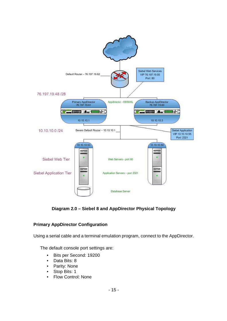
Diagram 2.0 – Siebel 8 and AppDirector Physical Top ology
Primary AppDirector Configuration Using a serial cable and a terminal emulation program, connect to the AppDirector.
The default console port settings are:
• Bits per Second: 19200 • Data Bits: 8 • Parity: None • Stop Bits: 1 • Flow Control: None
- 16 -
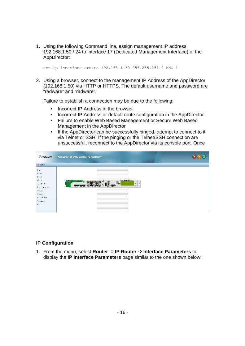
1. Using the following Command line, assign management IP address
192.168.1.50 / 24 to interface 17 (Dedicated Management Interface) of the AppDirector:
net ip-interface create 192.168.1.50 255.255.255.0 MNG-1
2. Using a browser, connect to the management IP Address of the AppDirector (192.168.1.50) via HTTP or HTTPS. The default username and password are “radware” and “radware”.
Failure to establish a connection may be due to the following:
• Incorrect IP Address in the browser • Incorrect IP Address or default route configuration in the AppDirector • Failure to enable Web Based Management or Secure Web Based
Management in the AppDirector • If the AppDirector can be successfully pinged, attempt to connect to it
via Telnet or SSH. If the pinging or the Telnet/SSH connection are unsuccessful, reconnect to the AppDirector via its console port. Once
IP Configuration
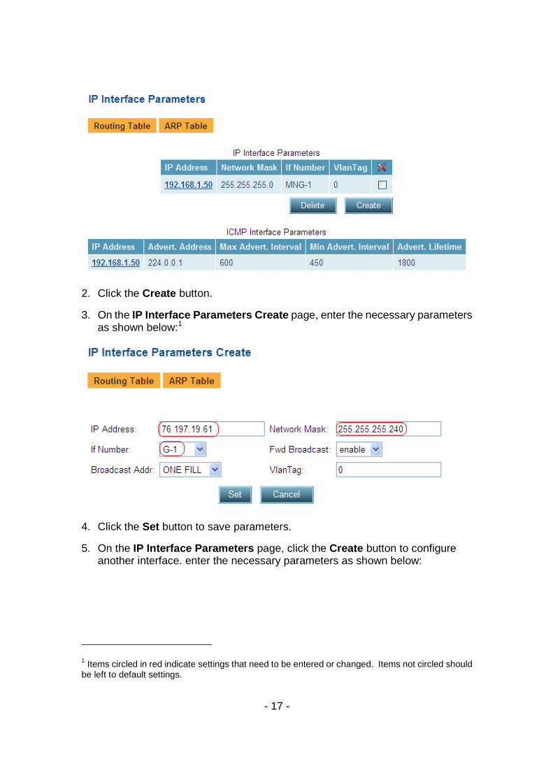
1. From the menu, select Router ���� IP Router ���� Interface Parameters to display the IP Interface Parameters page similar to the one shown below:
- 17 -
2. Click the Create button.
3. On the IP Interface Parameters Create page, enter the necessary parameters as shown below:1
4. Click the Set button to save parameters.
5. On the IP Interface Parameters page, click the Create button to configure another interface. enter the necessary parameters as shown below:
1 Items circled in red indicate settings that need to be entered or changed. Items not circled should be left to default settings.
- 18 -
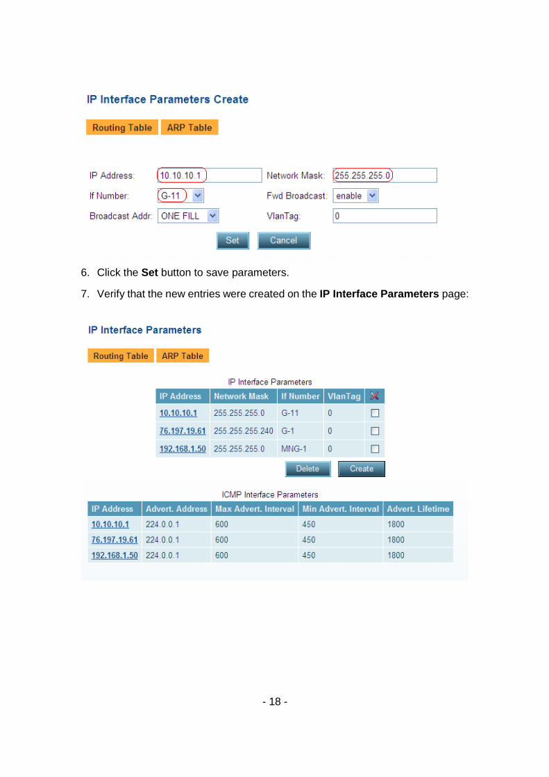
6. Click the Set button to save parameters.
7. Verify that the new entries were created on the IP Interface Parameters page:
- 19 -
Farm Configuration
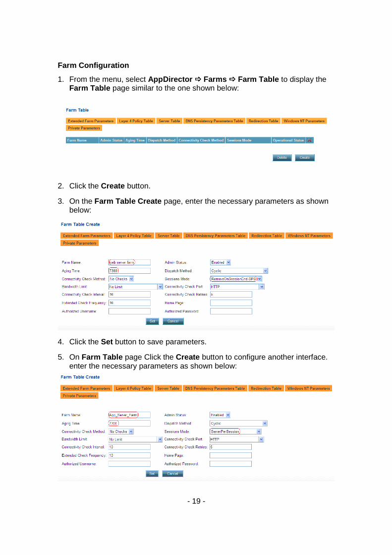
1. From the menu, select AppDirector ���� Farms ���� Farm Table to display the Farm Table page similar to the one shown below:
2. Click the Create button.
3. On the Farm Table Create page, enter the necessary parameters as shown below:
4. Click the Set button to save parameters.
5. On Farm Table page Click the Create button to configure another interface. enter the necessary parameters as shown below:
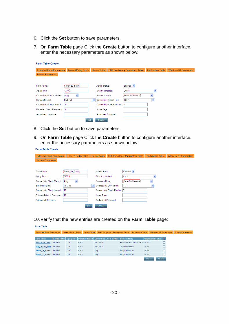
- 20 -
6. Click the Set button to save parameters.
7. On Farm Table page Click the Create button to configure another interface. enter the necessary parameters as shown below:
8. Click the Set button to save parameters.
9. On Farm Table page Click the Create button to configure another interface. enter the necessary parameters as shown below:
10. Verify that the new entries are created on the Farm Table page:
- 21 -
Create Layer 7 Policy Note: AppDirector needs to be configured with L7 rules in order to load balance Seibel application layer. There are three rules that need to be defined:
1. The first time a request is established for a new connection. 2. When the server needs to reconnect back to the same server after a
disconnect occurs 3. When the Siebel Broker detects that no AOM is available that the
request should be Round Robin load balanced to the next broker to handle the request.
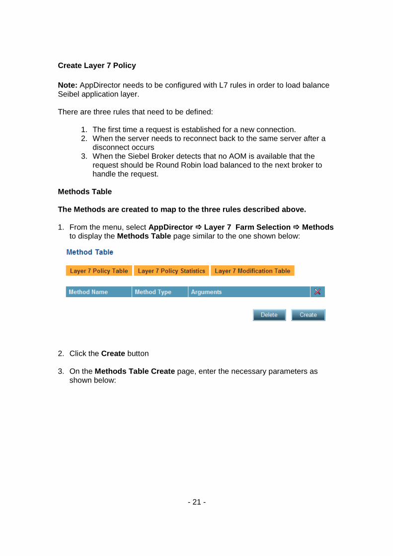
Methods Table The Methods are created to map to the three rules d escribed above. 1. From the menu, select AppDirector ���� Layer 7 Farm Selection ���� Methods
to display the Methods Table page similar to the one shown below:
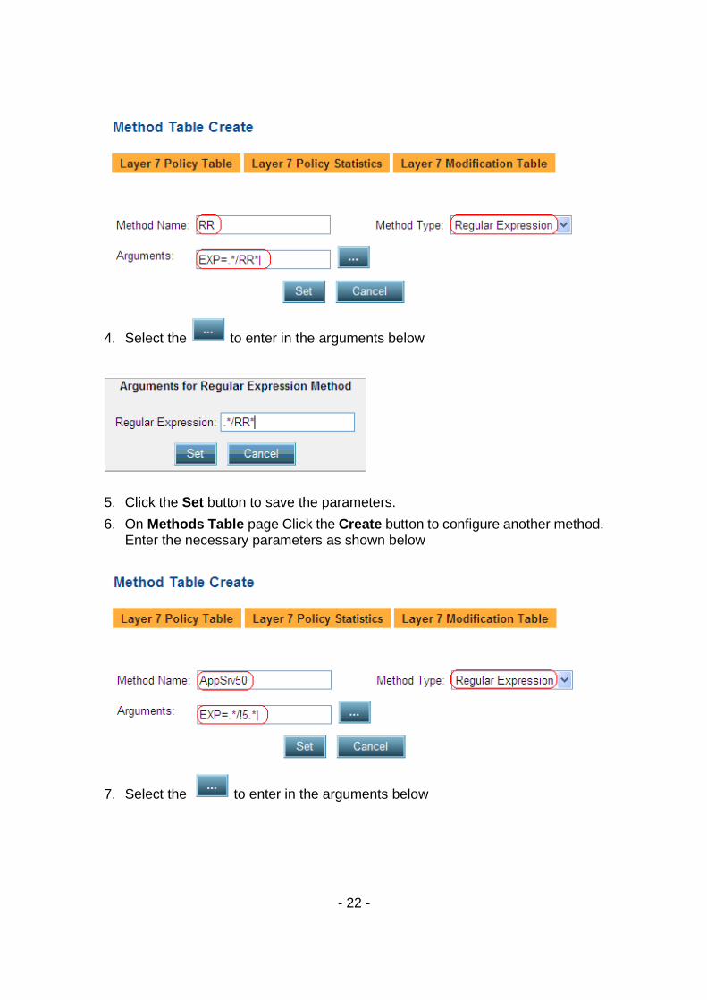
2. Click the Create button 3. On the Methods Table Create page, enter the necessary parameters as
shown below:
- 22 -
4. Select the to enter in the arguments below
5. Click the Set button to save the parameters.
6. On Methods Table page Click the Create button to configure another method. Enter the necessary parameters as shown below
7. Select the to enter in the arguments below
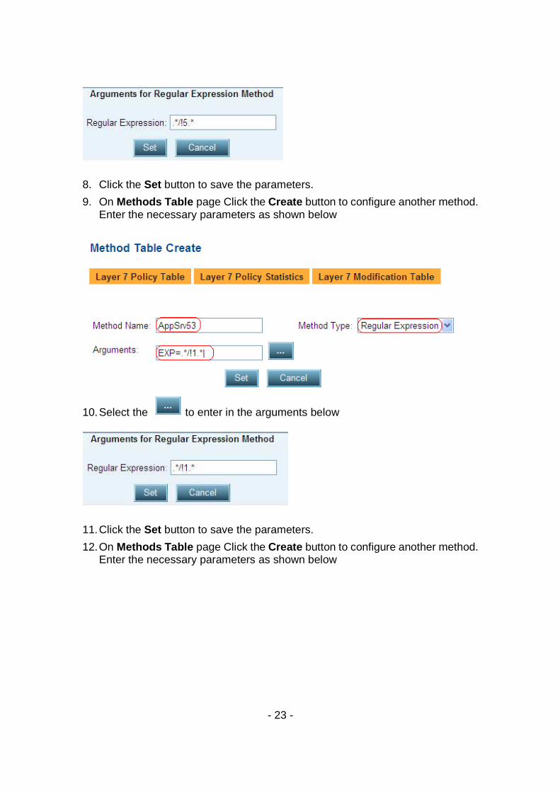
- 23 -
8. Click the Set button to save the parameters.
9. On Methods Table page Click the Create button to configure another method. Enter the necessary parameters as shown below
10. Select the to enter in the arguments below
11. Click the Set button to save the parameters.
12. On Methods Table page Click the Create button to configure another method. Enter the necessary parameters as shown below
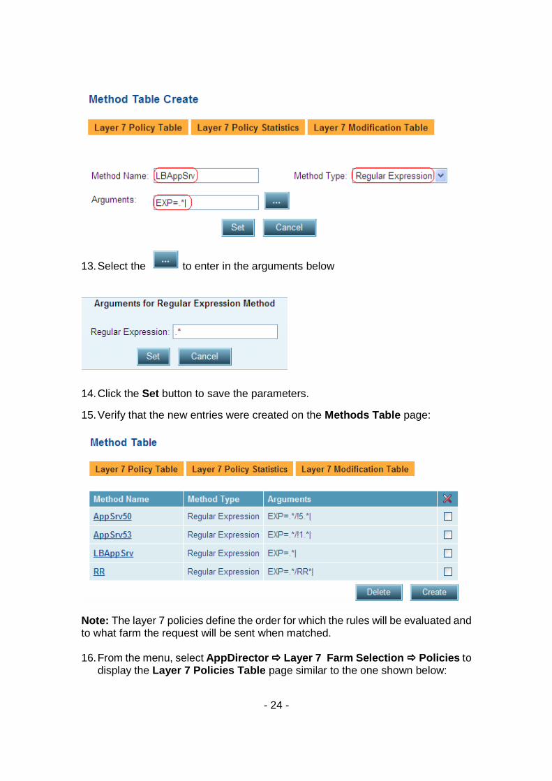
- 24 -
13. Select the to enter in the arguments below
14. Click the Set button to save the parameters.
15. Verify that the new entries were created on the Methods Table page:
Note: The layer 7 policies define the order for which the rules will be evaluated and to what farm the request will be sent when matched. 16. From the menu, select AppDirector ���� Layer 7 Farm Selection ���� Policies to
display the Layer 7 Policies Table page similar to the one shown below:
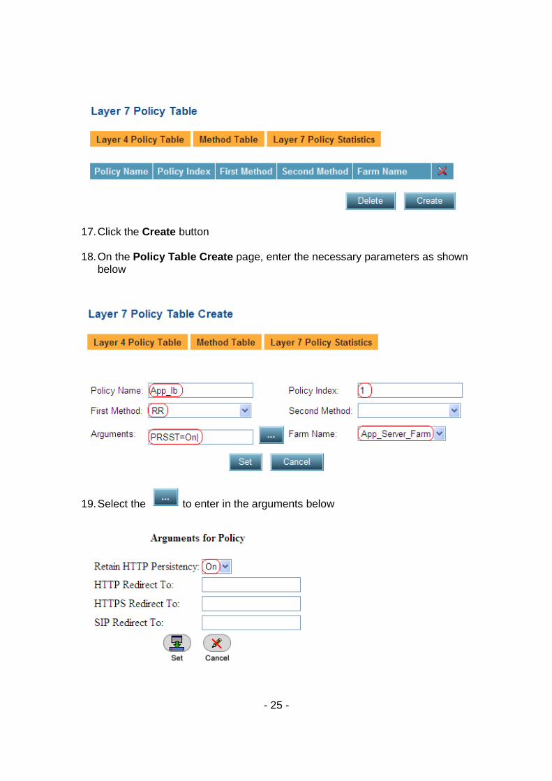
- 25 -
17. Click the Create button 18. On the Policy Table Create page, enter the necessary parameters as shown
below
19. Select the to enter in the arguments below
- 26 -
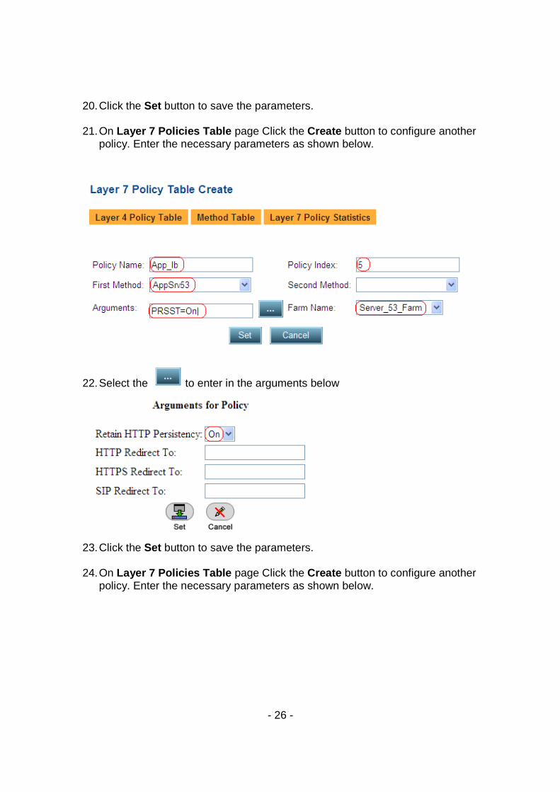
20. Click the Set button to save the parameters.
21. On Layer 7 Policies Table page Click the Create button to configure another
policy. Enter the necessary parameters as shown below.
22. Select the to enter in the arguments below
23. Click the Set button to save the parameters.
24. On Layer 7 Policies Table page Click the Create button to configure another
policy. Enter the necessary parameters as shown below.
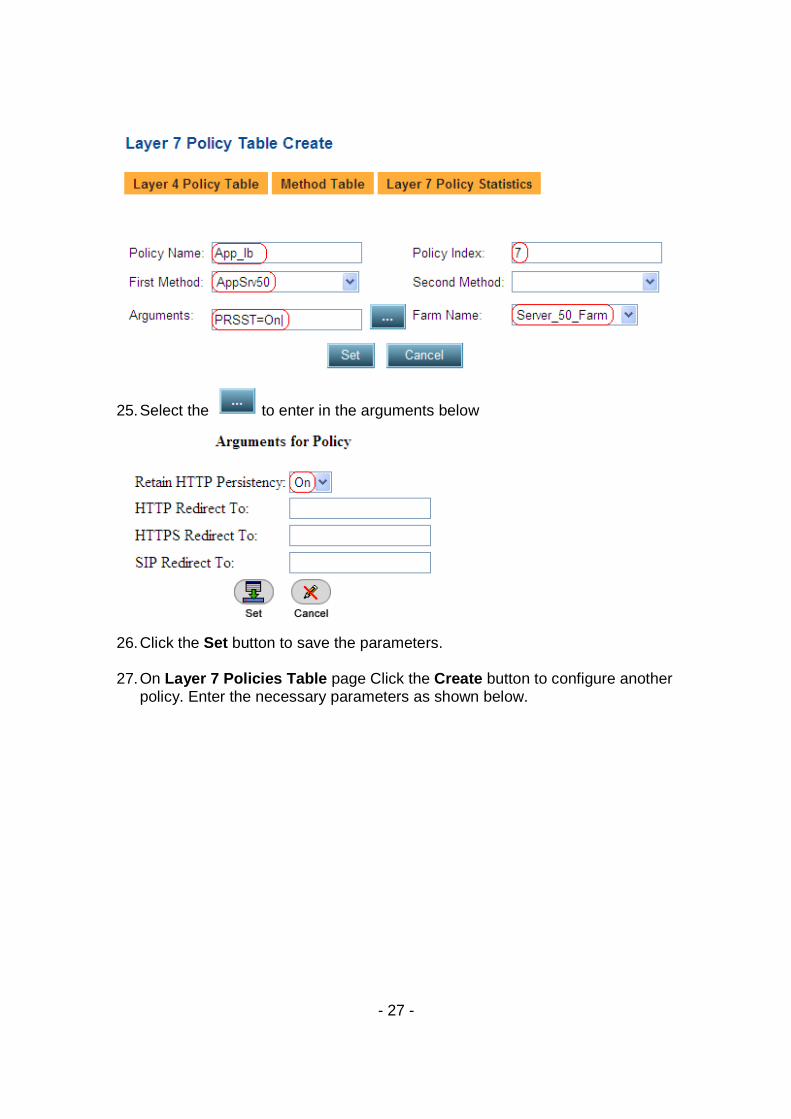
- 27 -
25. Select the to enter in the arguments below
26. Click the Set button to save the parameters.
27. On Layer 7 Policies Table page Click the Create button to configure another
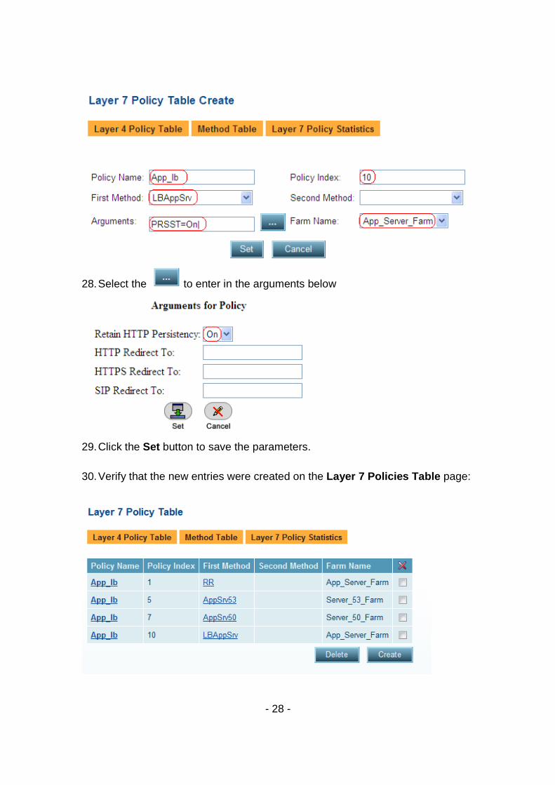
policy. Enter the necessary parameters as shown below.
- 28 -
28. Select the to enter in the arguments below
29. Click the Set button to save the parameters.
30. Verify that the new entries were created on the Layer 7 Policies Table page:
- 29 -
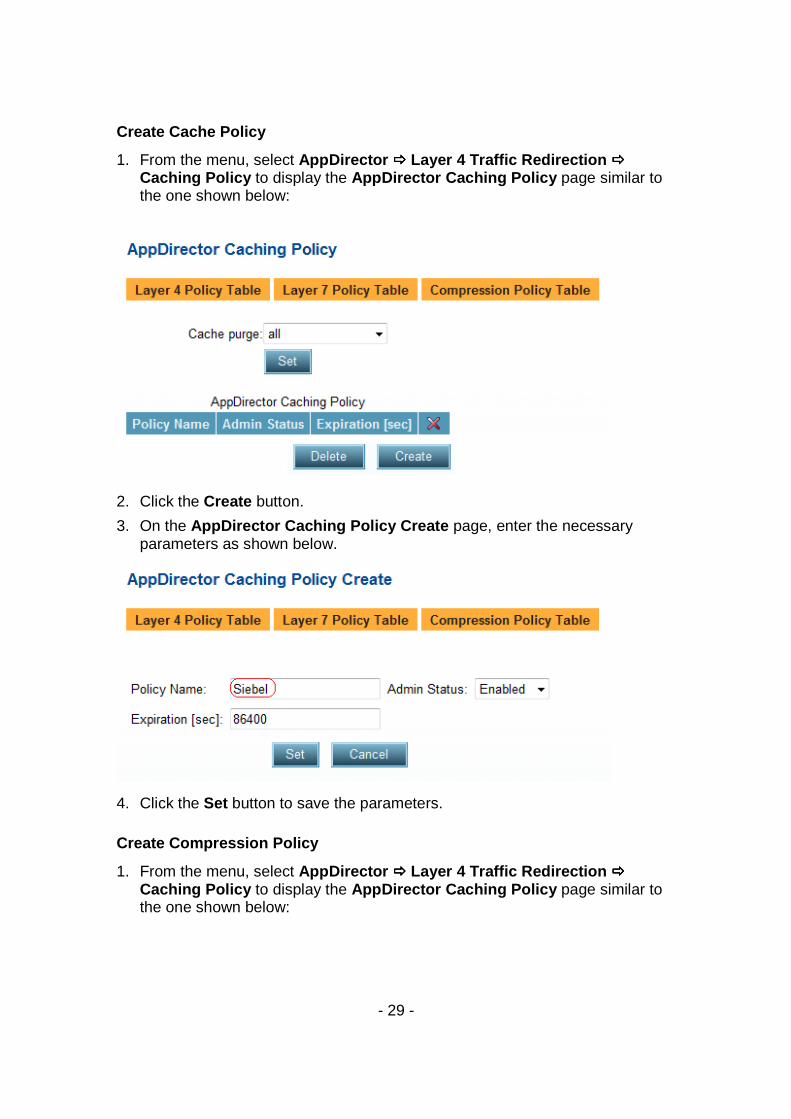
Create Cache Policy
1. From the menu, select AppDirector ���� Layer 4 Traffic Redirection ���� Caching Policy to display the AppDirector Caching Policy page similar to the one shown below:
2. Click the Create button.
3. On the AppDirector Caching Policy Create page, enter the necessary parameters as shown below.
4. Click the Set button to save the parameters.
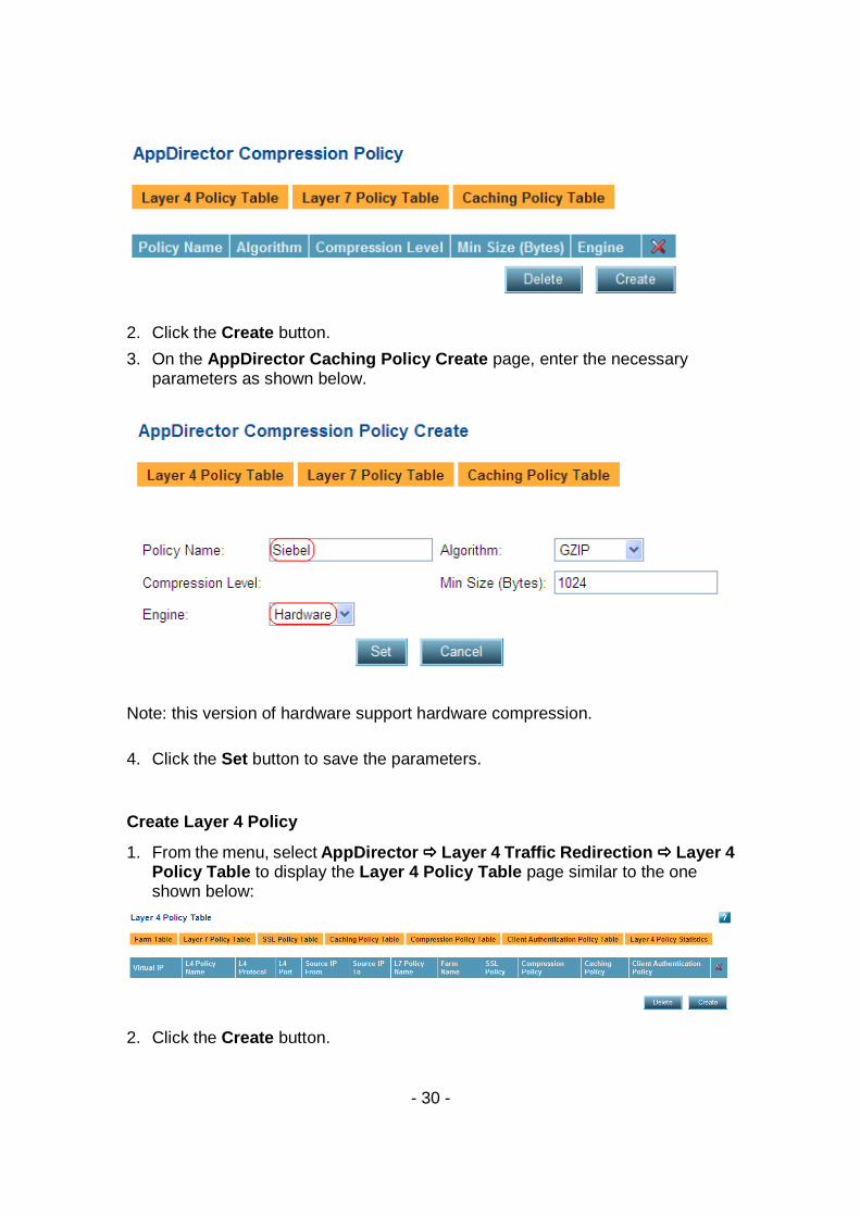
Create Compression Policy
1. From the menu, select AppDirector ���� Layer 4 Traffic Redirection ���� Caching Policy to display the AppDirector Caching Policy page similar to the one shown below:
- 30 -
2. Click the Create button.
3. On the AppDirector Caching Policy Create page, enter the necessary parameters as shown below.
Note: this version of hardware support hardware compression.
4. Click the Set button to save the parameters.
Create Layer 4 Policy
1. From the menu, select AppDirector ���� Layer 4 Traffic Redirection ���� Layer 4 Policy Table to display the Layer 4 Policy Table page similar to the one shown below:
2. Click the Create button.
- 31 -
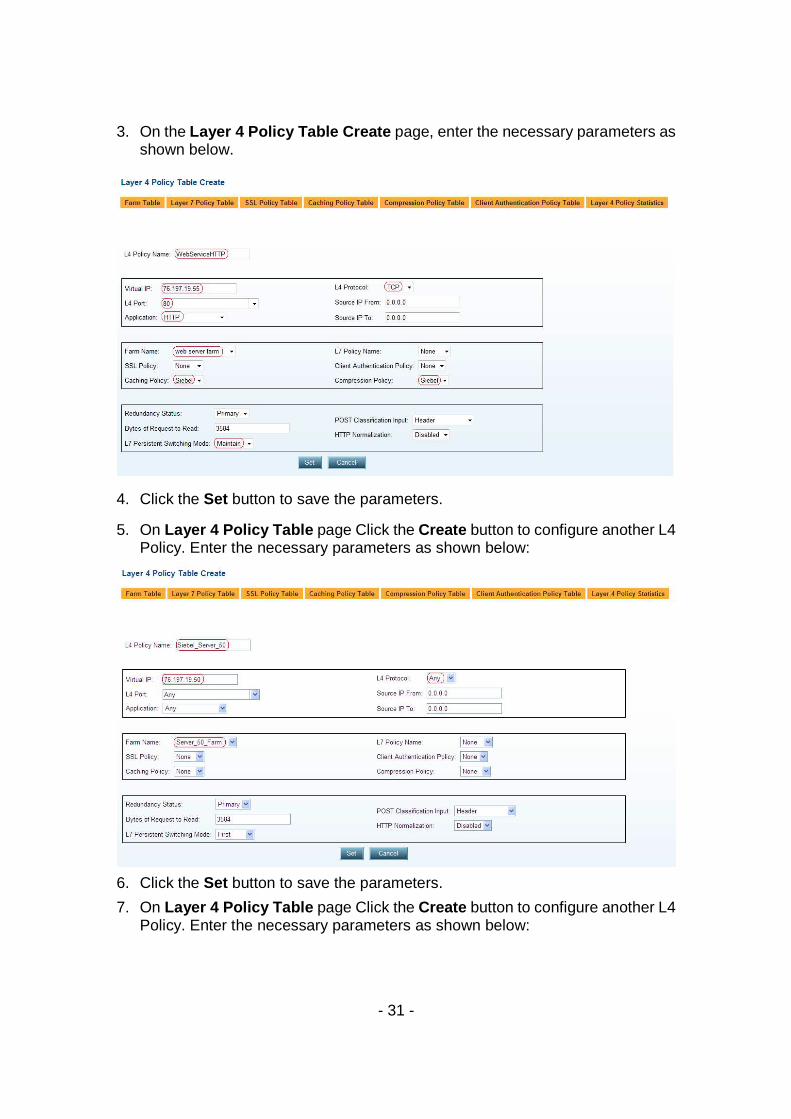
3. On the Layer 4 Policy Table Create page, enter the necessary parameters as shown below.
4. Click the Set button to save the parameters.
5. On Layer 4 Policy Table page Click the Create button to configure another L4 Policy. Enter the necessary parameters as shown below:
6. Click the Set button to save the parameters.
7. On Layer 4 Policy Table page Click the Create button to configure another L4 Policy. Enter the necessary parameters as shown below:
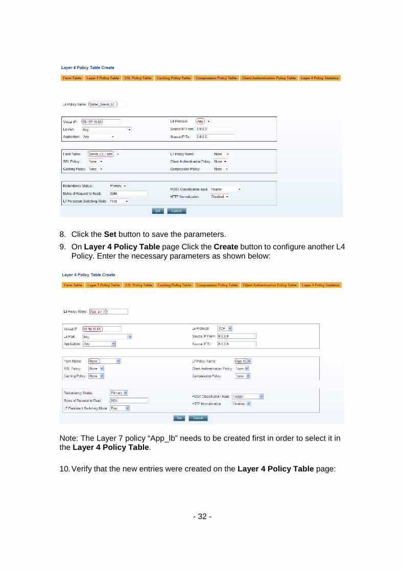
- 32 -
8. Click the Set button to save the parameters.
9. On Layer 4 Policy Table page Click the Create button to configure another L4 Policy. Enter the necessary parameters as shown below:
Note: The Layer 7 policy “App_lb” needs to be created first in order to select it in the Layer 4 Policy Table .
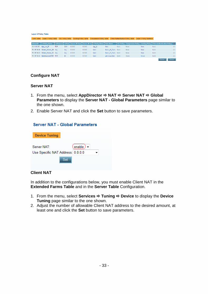
10. Verify that the new entries were created on the Layer 4 Policy Table page:
- 33 -
Configure NAT Server NAT 1. From the menu, select AppDirector ���� NAT ���� Server NAT ���� Global
Parameters to display the Server NAT - Global Parameters page similar to the one shown.
2. Enable Server NAT and click the Set button to save parameters.
Client NAT In addition to the configurations below, you must enable Client NAT in the Extended Farms Table and in the Server Table Configuration. 1. From the menu, select Services ���� Tuning ���� Device to display the Device
Tuning page similar to the one shown. 2. Adjust the number of allowable Client NAT address to the desired amount, at
least one and click the Set button to save parameters.
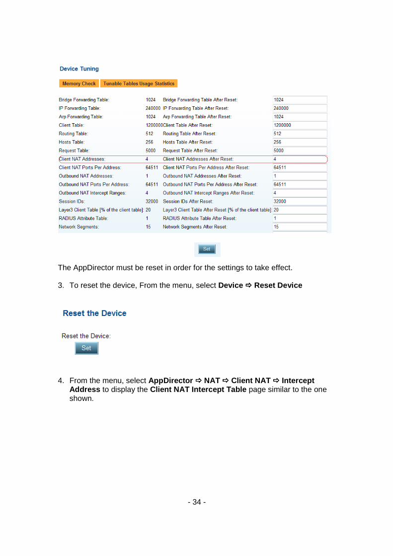
- 34 -
The AppDirector must be reset in order for the settings to take effect. 3. To reset the device, From the menu, select Device ���� Reset Device
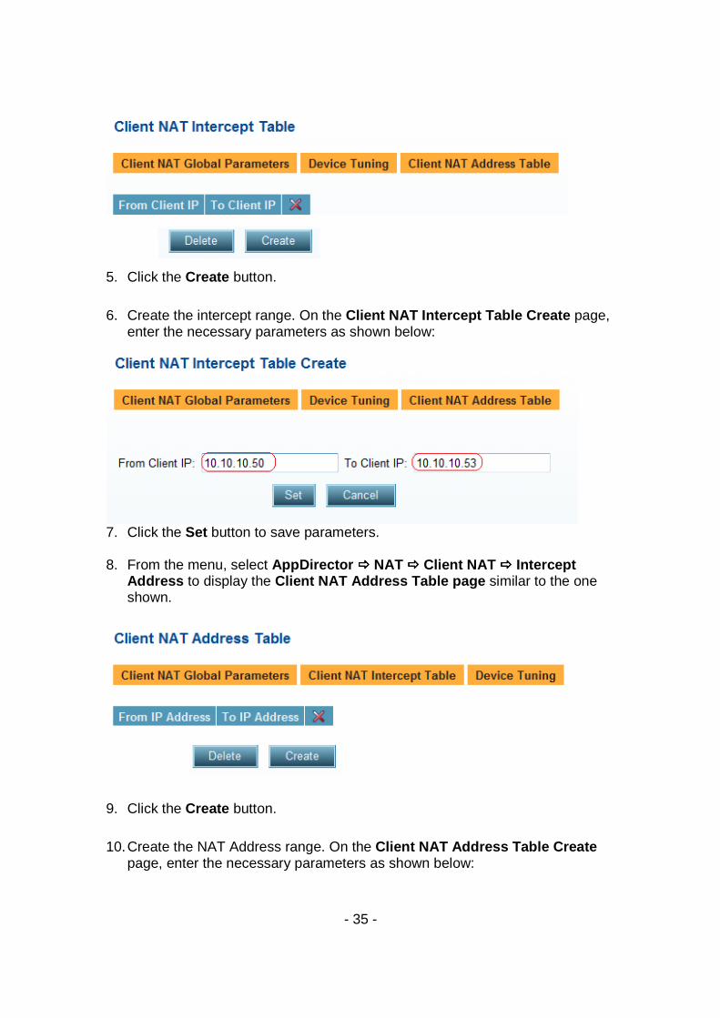
4. From the menu, select AppDirector ���� NAT ���� Client NAT ���� Intercept Address to display the Client NAT Intercept Table page similar to the one shown.
- 35 -
5. Click the Create button.
6. Create the intercept range. On the Client NAT Intercept Table Create page, enter the necessary parameters as shown below:
7. Click the Set button to save parameters. 8. From the menu, select AppDirector ���� NAT ���� Client NAT ���� Intercept
Address to display the Client NAT Address Table page similar to the one shown.
9. Click the Create button.
10. Create the NAT Address range. On the Client NAT Address Table Create page, enter the necessary parameters as shown below:
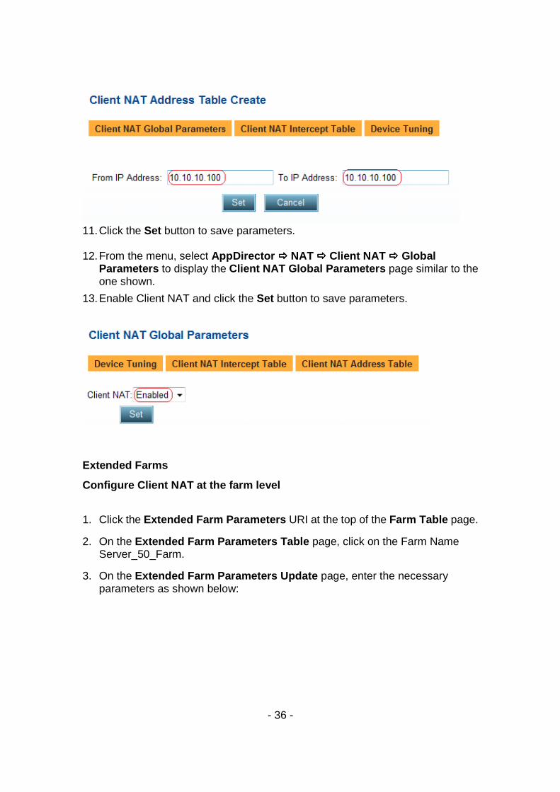
- 36 -
11. Click the Set button to save parameters. 12. From the menu, select AppDirector ���� NAT ���� Client NAT ���� Global
Parameters to display the Client NAT Global Parameters page similar to the one shown.
13. Enable Client NAT and click the Set button to save parameters.
Extended Farms
Configure Client NAT at the farm level
1. Click the Extended Farm Parameters URI at the top of the Farm Table page.
2. On the Extended Farm Parameters Table page, click on the Farm Name Server_50_Farm.
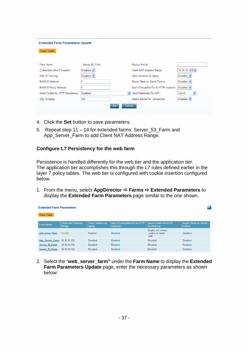
3. On the Extended Farm Parameters Update page, enter the necessary parameters as shown below:
- 37 -
4. Click the Set button to save parameters.
5. Repeat step 11 – 14 for extended farms: Server_53_Farm and App_Server_Farm to add Client NAT Address Range.
Configure L7 Persistency for the web farm
Persistence is handled differently for the web tier and the application tier. The application tier accomplishes this through the L7 rules defined earlier in the layer 7 policy tables. The web tier is configured with cookie insertion configured below. 1. From the menu, select AppDirector ���� Farms ���� Extended Parameters to
display the Extended Farm Parameters page similar to the one shown.
2. Select the “web_server_farm” under the Farm Name to display the Extended
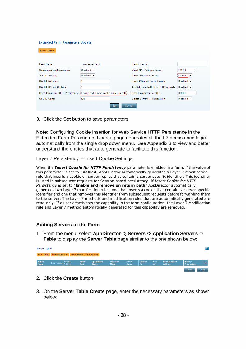
Farm Parameters Update page, enter the necessary parameters as shown below:
- 38 -
3. Click the Set button to save parameters.
Note : Configuring Cookie Insertion for Web Service HTTP Persistence in the Extended Farm Parameters Update page generates all the L7 persistence logic automatically from the single drop down menu. See Appendix 3 to view and better understand the entries that auto generate to facilitate this function.
Layer 7 Persistency – Insert Cookie Settings
When the Insert Cookie for HTTP Persistency parameter is enabled in a farm, if the value of
this parameter is set to Enabled, AppDirector automatically generates a Layer 7 modification rule that inserts a cookie on server replies that contain a server specific identifier. This identifier
is used in subsequent requests for Session based persistency. If Insert Cookie for HTTP Persistency is set to “Enable and remove on return path" AppDirector automatically
generates two Layer 7 modification rules, one that inserts a cookie that contains a server specific identifier and one that removes this identifier from subsequent requests before forwarding them
to the server. The Layer 7 methods and modification rules that are automatically generated are
read-only. If a user deactivates the capability in the farm configuration, the Layer 7 Modification rule and Layer 7 method automatically generated for this capability are removed.
Adding Servers to the Farm
1. From the menu, select AppDirector ���� Servers ���� Application Servers ���� Table to display the Server Table page similar to the one shown below:
2. Click the Create button
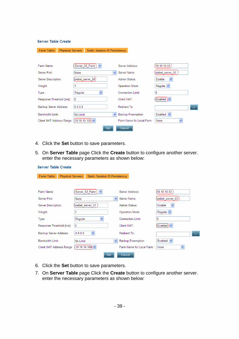
3. On the Server Table Create page, enter the necessary parameters as shown below:
- 39 -
4. Click the Set button to save parameters.
5. On Server Table page Click the Create button to configure another server. enter the necessary parameters as shown below:
6. Click the Set button to save parameters.
7. On Server Table page Click the Create button to configure another server. enter the necessary parameters as shown below:
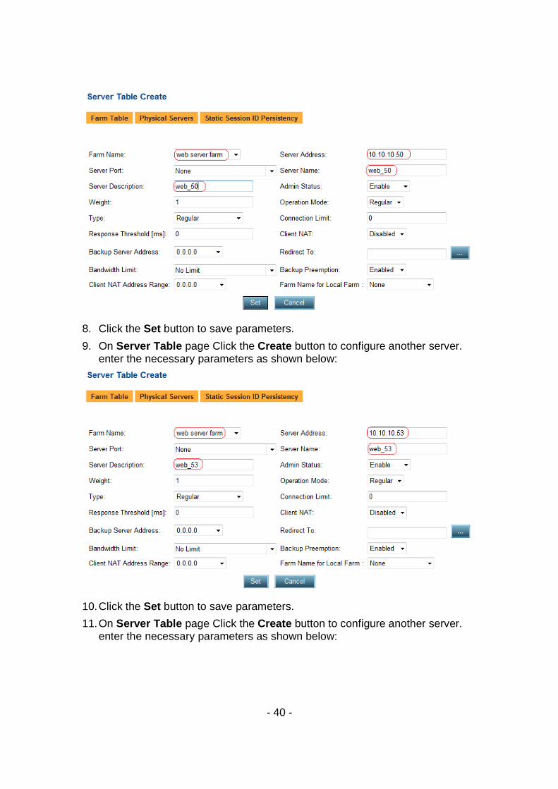
- 40 -
8. Click the Set button to save parameters.
9. On Server Table page Click the Create button to configure another server. enter the necessary parameters as shown below:
10. Click the Set button to save parameters.
11. On Server Table page Click the Create button to configure another server. enter the necessary parameters as shown below:
- 41 -
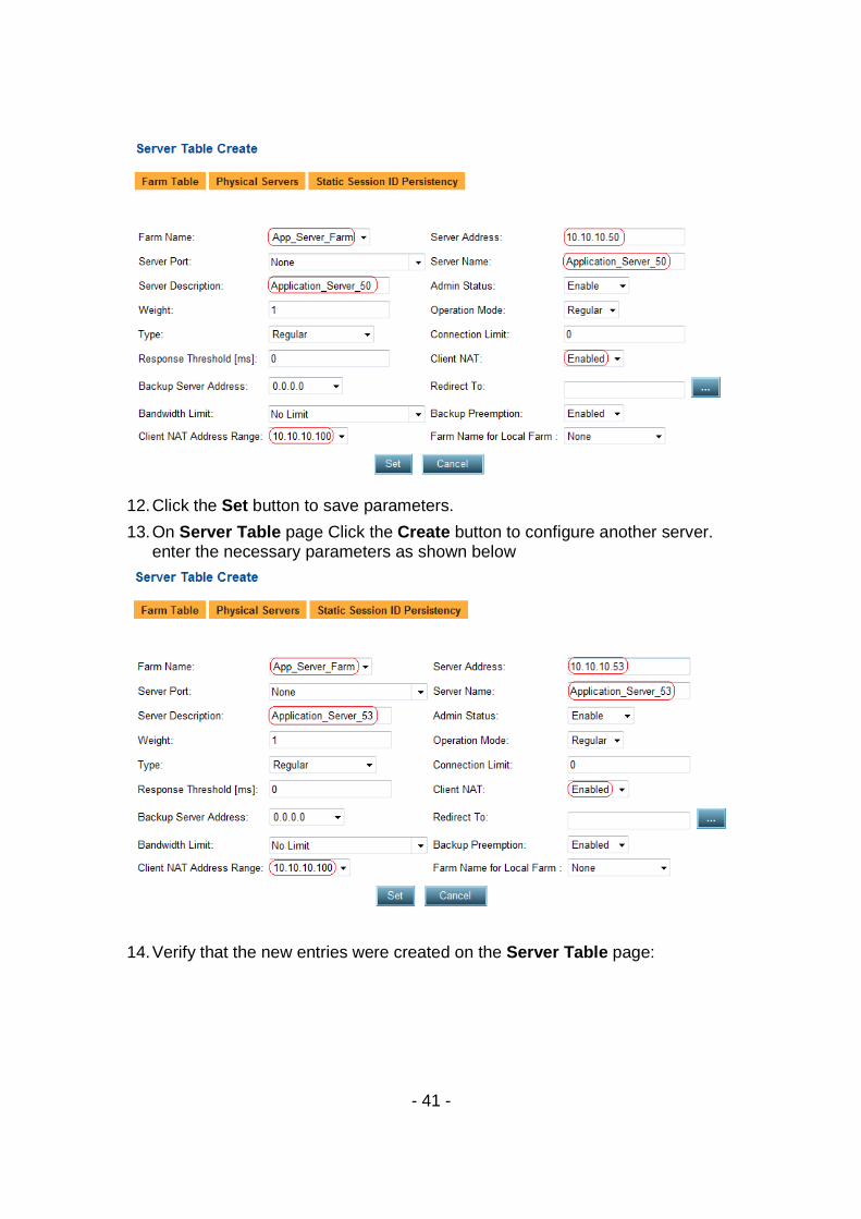
12. Click the Set button to save parameters.
13. On Server Table page Click the Create button to configure another server. enter the necessary parameters as shown below
14. Verify that the new entries were created on the Server Table page:

- 42 -
Health Monitoring Create Health Checks
1. From the menu, select Health Monitoring ���� Global Parameters to display the Health Monitoring Global Parameters page.
2. On the Health Monitoring Global Parameters page, change the parameters as shown below:
3. Click the Set button to save parameters.
4. Create the Health Monitoring Checks.
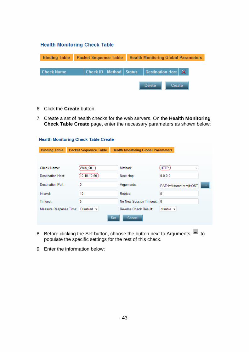
5. From the menu, select Health Monitoring ���� Check Table to display the Health Monitoring Check Table page similar to the one shown below:
- 43 -
6. Click the Create button.
7. Create a set of health checks for the web servers. On the Health Monitoring Check Table Create page, enter the necessary parameters as shown below:
8. Before clicking the Set button, choose the button next to Arguments to populate the specific settings for the rest of this check.
9. Enter the information below:

- 44 -
10. Click the Set button for the Method Arguments and click the Set button again in the Health Monitoring Check Table Create window.
11. Follow steps 5-10 to create the second server health check for web server web_53, host 10.10.10.53.
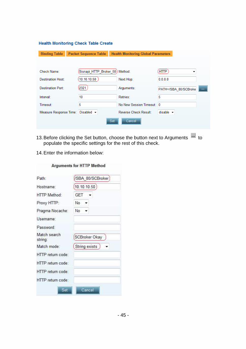
12. Create a second set of health checks for the application servers. On the Health Monitoring Check Table Create page, enter the necessary parameters as shown below:
- 45 -
13. Before clicking the Set button, choose the button next to Arguments to populate the specific settings for the rest of this check.
14. Enter the information below:
- 46 -
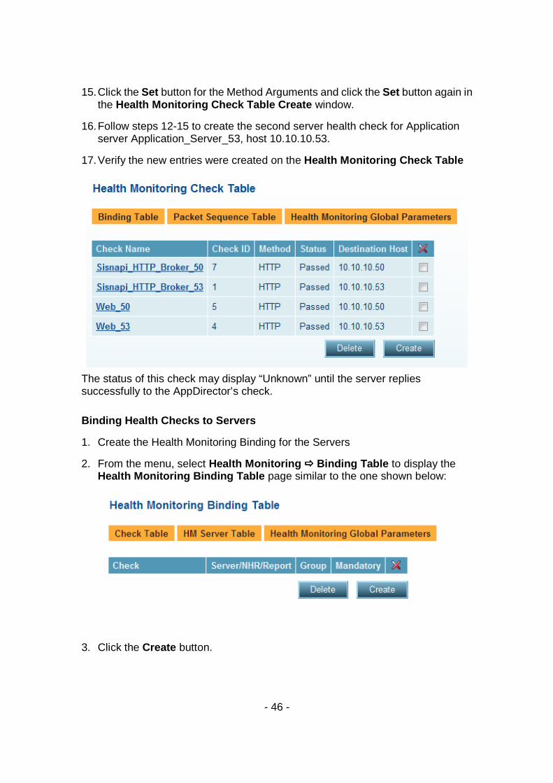
15. Click the Set button for the Method Arguments and click the Set button again in the Health Monitoring Check Table Create window.
16. Follow steps 12-15 to create the second server health check for Application server Application_Server_53, host 10.10.10.53.
17. Verify the new entries were created on the Health Monitoring Check Table
The status of this check may display “Unknown” until the server replies successfully to the AppDirector’s check.
Binding Health Checks to Servers
1. Create the Health Monitoring Binding for the Servers
2. From the menu, select Health Monitoring ���� Binding Table to display the Health Monitoring Binding Table page similar to the one shown below:
3. Click the Create button.

- 47 -
4. Create the health check binding for the web servers. On the Health Monitoring Binding Table Create page, enter the necessary parameters as shown below:
5. Click the Set button to save parameters.
6. Follow steps 2-5 to bind the second web server health check. Web_53: Farm web server farm - 10.10.10.53 – 0
7. Create the health check binding for the application servers. On the Health Monitoring Binding Table Create page, enter the necessary parameters as shown below:
8. Click the Set button to save parameters.
9. Follow steps 7-8 to bind the second application server health check. Sisnapi_HTTP_Broker_53: Farm web server farm - 10.10.10.53 – 0
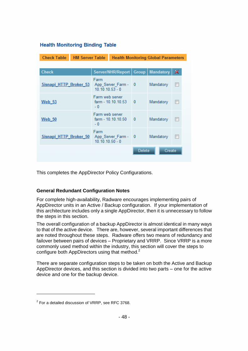
10. Verify that the new entries were created on the Health Monitoring Binding Table page:
- 48 -
This completes the AppDirector Policy Configurations.
General Redundant Configuration Notes
For complete high-availability, Radware encourages implementing pairs of AppDirector units in an Active / Backup configuration. If your implementation of this architecture includes only a single AppDirector, then it is unnecessary to follow the steps in this section.
The overall configuration of a backup AppDirector is almost identical in many ways to that of the active device. There are, however, several important differences that are noted throughout these steps. Radware offers two means of redundancy and failover between pairs of devices – Proprietary and VRRP. Since VRRP is a more commonly used method within the industry, this section will cover the steps to configure both AppDirectors using that method.2 There are separate configuration steps to be taken on both the Active and Backup AppDirector devices, and this section is divided into two parts – one for the active device and one for the backup device.
2 For a detailed discussion of VRRP, see RFC 3768.
- 49 -
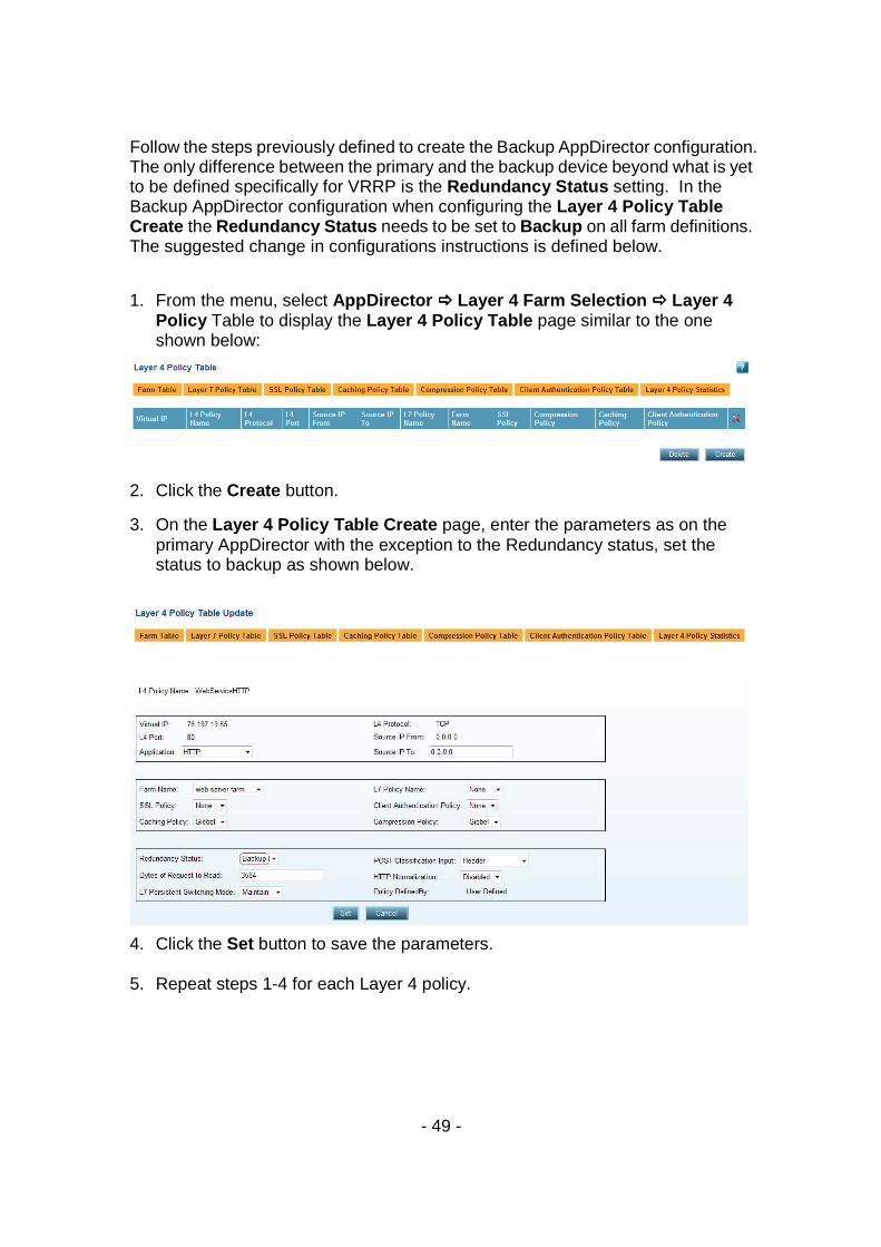
Follow the steps previously defined to create the Backup AppDirector configuration. The only difference between the primary and the backup device beyond what is yet to be defined specifically for VRRP is the Redundancy Status setting. In the Backup AppDirector configuration when configuring the Layer 4 Policy Table Create the Redundancy Status needs to be set to Backup on all farm definitions. The suggested change in configurations instructions is defined below.
1. From the menu, select AppDirector ���� Layer 4 Farm Selection ���� Layer 4 Policy Table to display the Layer 4 Policy Table page similar to the one shown below:
2. Click the Create button.
3. On the Layer 4 Policy Table Create page, enter the parameters as on the primary AppDirector with the exception to the Redundancy status, set the status to backup as shown below.
4. Click the Set button to save the parameters.
5. Repeat steps 1-4 for each Layer 4 policy.
- 50 -
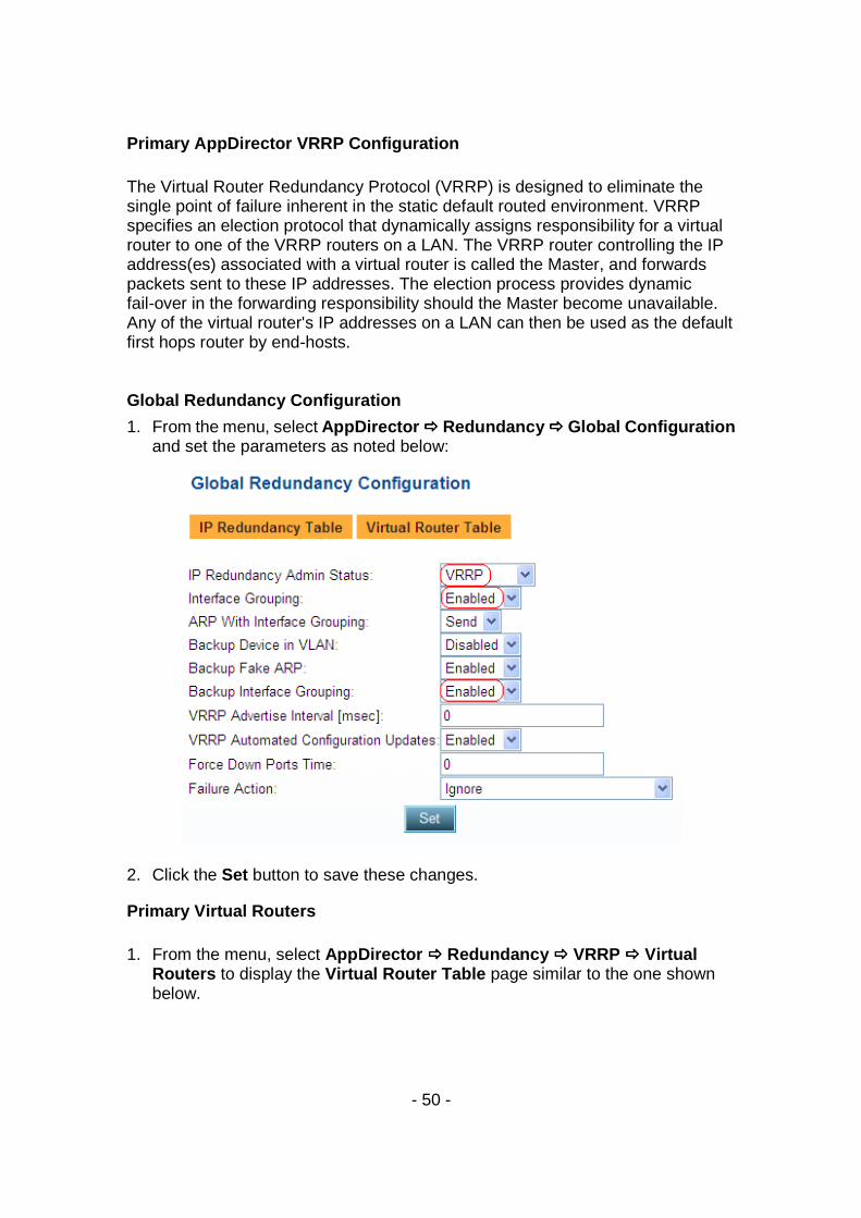
Primary AppDirector VRRP Configuration The Virtual Router Redundancy Protocol (VRRP) is designed to eliminate the single point of failure inherent in the static default routed environment. VRRP specifies an election protocol that dynamically assigns responsibility for a virtual router to one of the VRRP routers on a LAN. The VRRP router controlling the IP address(es) associated with a virtual router is called the Master, and forwards packets sent to these IP addresses. The election process provides dynamic fail-over in the forwarding responsibility should the Master become unavailable. Any of the virtual router's IP addresses on a LAN can then be used as the default first hops router by end-hosts. Global Redundancy Configuration
1. From the menu, select AppDirector ���� Redundancy ���� Global Configuration and set the parameters as noted below:
2. Click the Set button to save these changes.
Primary Virtual Routers 1. From the menu, select AppDirector ���� Redundancy ���� VRRP ���� Virtual
Routers to display the Virtual Router Table page similar to the one shown below.

- 51 -
2. Click the Create button
3. On the Virtual Router Table page, enter the necessary parameters as shown below.
4. Click the Set button to save the parameters.
5. On the Virtual Router Table Create page, click the Create button to configure another interface. enter the necessary parameters as shown below:
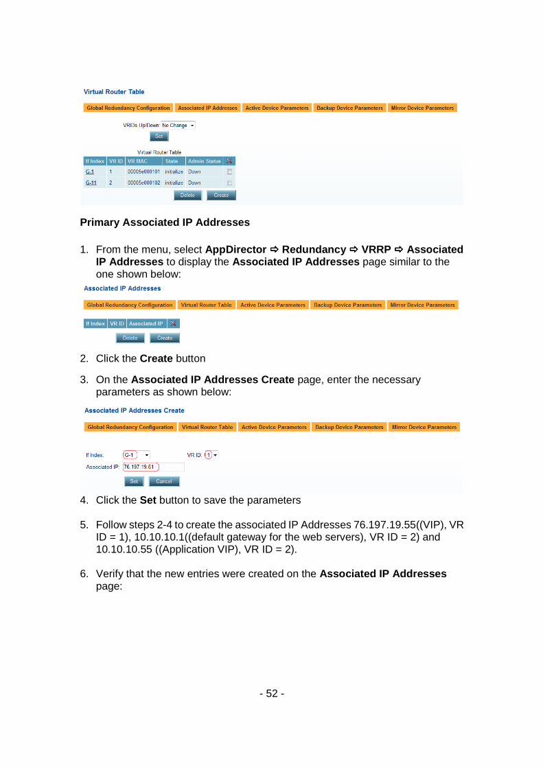
6. Click the Set button to save the parameters. 7. Verify that the new entries were created on the Virtual Router Table page:
- 52 -
Primary Associated IP Addresses 1. From the menu, select AppDirector ���� Redundancy ���� VRRP ���� Associated
IP Addresses to display the Associated IP Addresses page similar to the one shown below:
2. Click the Create button
3. On the Associated IP Addresses Create page, enter the necessary parameters as shown below:
4. Click the Set button to save the parameters 5. Follow steps 2-4 to create the associated IP Addresses 76.197.19.55((VIP), VR
ID = 1), 10.10.10.1((default gateway for the web servers), VR ID = 2) and 10.10.10.55 ((Application VIP), VR ID = 2).
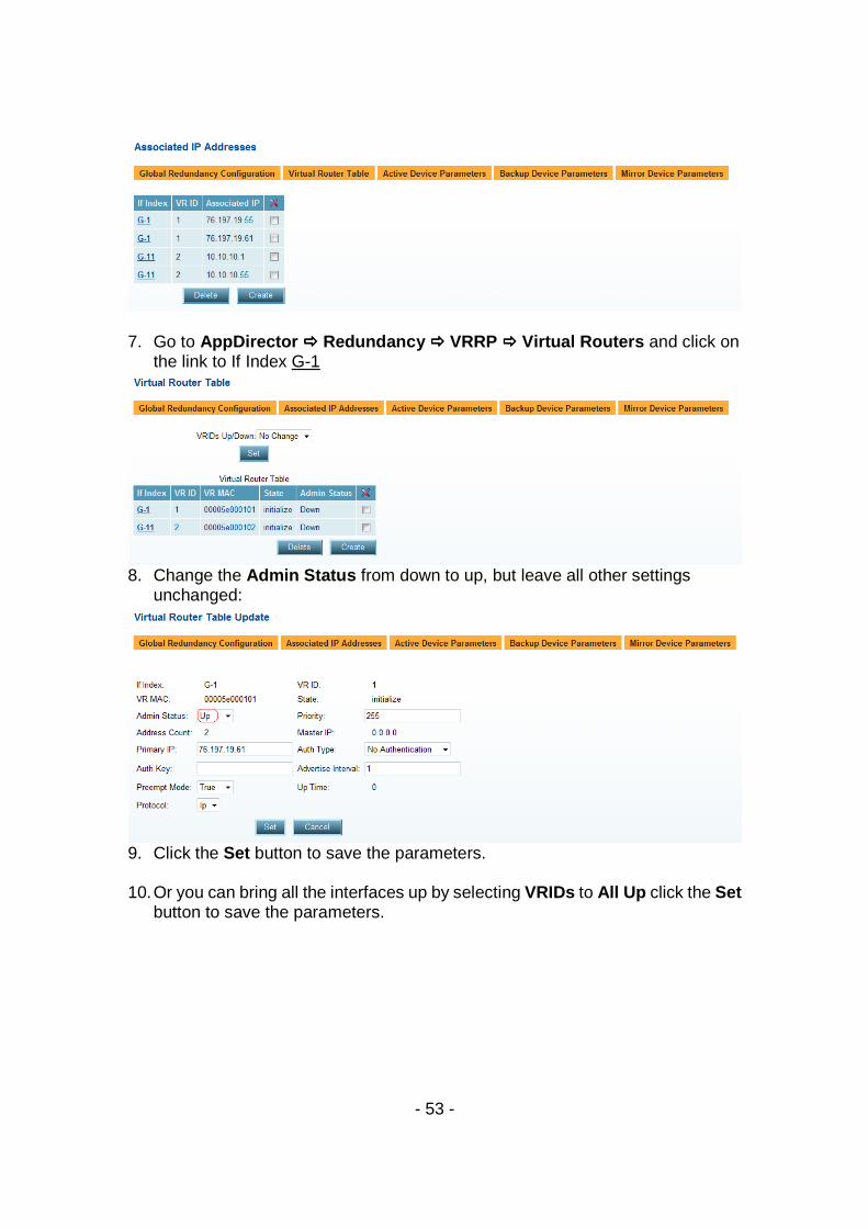
6. Verify that the new entries were created on the Associated IP Addresses
page:
- 53 -
7. Go to AppDirector ���� Redundancy ���� VRRP ���� Virtual Routers and click on
the link to If Index G-1
8. Change the Admin Status from down to up, but leave all other settings
unchanged:
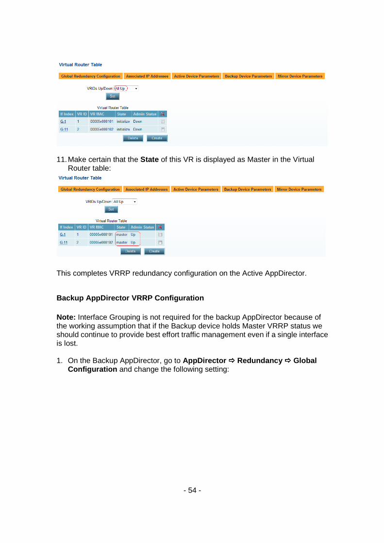
9. Click the Set button to save the parameters. 10. Or you can bring all the interfaces up by selecting VRIDs to All Up click the Set
button to save the parameters.
- 54 -
11. Make certain that the State of this VR is displayed as Master in the Virtual Router table:
This completes VRRP redundancy configuration on the Active AppDirector.
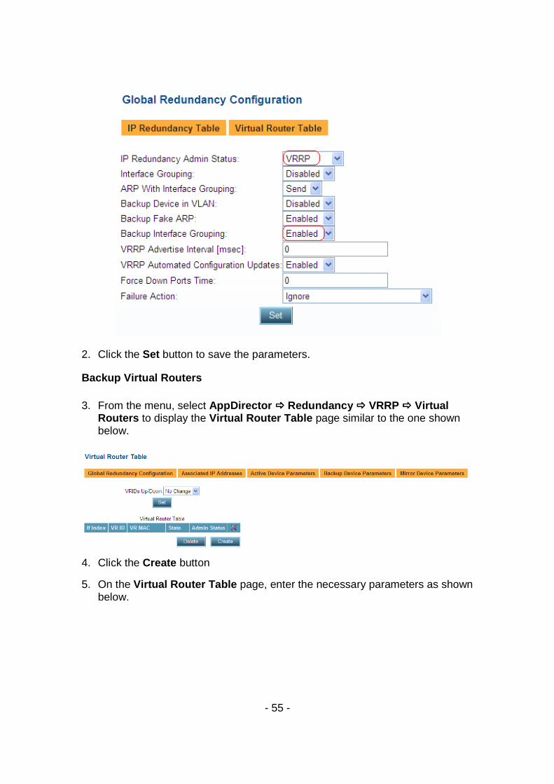
Backup AppDirector VRRP Configuration Note: Interface Grouping is not required for the backup AppDirector because of the working assumption that if the Backup device holds Master VRRP status we should continue to provide best effort traffic management even if a single interface is lost. 1. On the Backup AppDirector, go to AppDirector ���� Redundancy ���� Global
Configuration and change the following setting:
- 55 -
2. Click the Set button to save the parameters.
Backup Virtual Routers 3. From the menu, select AppDirector ���� Redundancy ���� VRRP ���� Virtual
Routers to display the Virtual Router Table page similar to the one shown below.
4. Click the Create button
5. On the Virtual Router Table page, enter the necessary parameters as shown below.
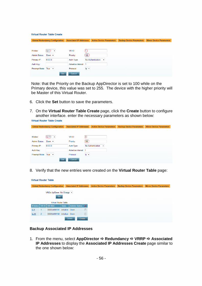
- 56 -
Note: that the Priority on the Backup AppDirector is set to 100 while on the Primary device, this value was set to 255. The device with the higher priority will be Master of this Virtual Router.
6. Click the Set button to save the parameters.
7. On the Virtual Router Table Create page, click the Create button to configure
another interface. enter the necessary parameters as shown below:
8. Verify that the new entries were created on the Virtual Router Table page:
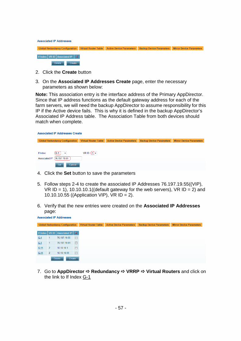
Backup Associated IP Addresses 1. From the menu, select AppDirector ���� Redundancy ���� VRRP ���� Associated
IP Addresses to display the Associated IP Addresses Create page similar to the one shown below:
- 57 -
2. Click the Create button
3. On the Associated IP Addresses Create page, enter the necessary parameters as shown below:
Note: This association entry is the interface address of the Primary AppDirector. Since that IP address functions as the default gateway address for each of the farm servers, we will need the backup AppDirector to assume responsibility for this IP if the Active device fails. This is why it is defined in the backup AppDirector’s Associated IP Address table. The Association Table from both devices should match when complete.
4. Click the Set button to save the parameters
5. Follow steps 2-4 to create the associated IP Addresses 76.197.19.55((VIP),
VR ID = 1), 10.10.10.1((default gateway for the web servers), VR ID = 2) and 10.10.10.55 ((Application VIP), VR ID = 2).
6. Verify that the new entries were created on the Associated IP Addresses
page:
7. Go to AppDirector ���� Redundancy ���� VRRP ���� Virtual Routers and click on
the link to If Index G-1
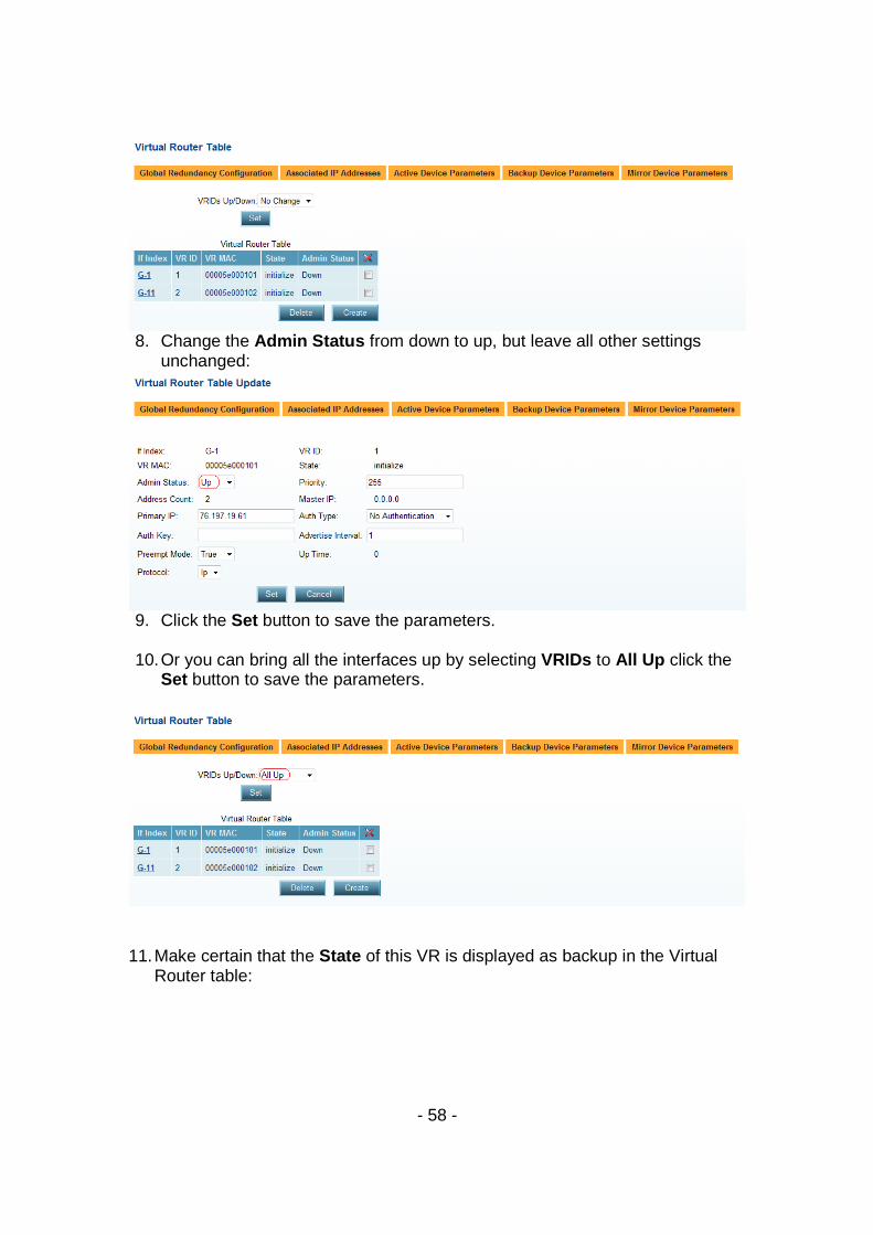
- 58 -
8. Change the Admin Status from down to up, but leave all other settings
unchanged:
9. Click the Set button to save the parameters.
10. Or you can bring all the interfaces up by selecting VRIDs to All Up click the
Set button to save the parameters.
11. Make certain that the State of this VR is displayed as backup in the Virtual
Router table:

- 59 -
This concludes the configuration of the Backup AppDirector and the local HA solution.
- 60 -
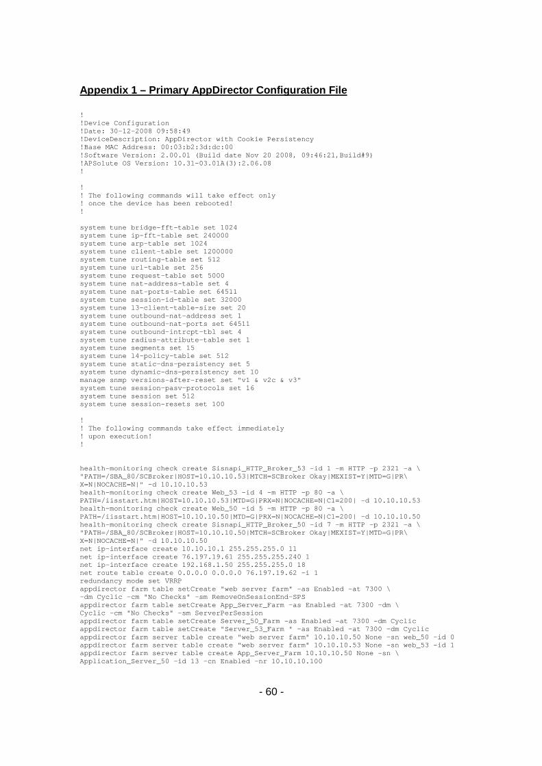
Appendix 1 – Primary AppDirector Configuration File ! !Device Configuration !Date: 30-12-2008 09:58:49 !DeviceDescription: AppDirector with Cookie Persistency !Base MAC Address: 00:03:b2:3d:dc:00 !Software Version: 2.00.01 (Build date Nov 20 2008, 09:46:21,Build#9) !APSolute OS Version: 10.31-03.01A(3):2.06.08 ! ! ! The following commands will take effect only ! once the device has been rebooted! ! system tune bridge-fft-table set 1024 system tune ip-fft-table set 240000 system tune arp-table set 1024 system tune client-table set 1200000 system tune routing-table set 512 system tune url-table set 256 system tune request-table set 5000 system tune nat-address-table set 4 system tune nat-ports-table set 64511 system tune session-id-table set 32000 system tune l3-client-table-size set 20 system tune outbound-nat-address set 1 system tune outbound-nat-ports set 64511 system tune outbound-intrcpt-tbl set 4 system tune radius-attribute-table set 1 system tune segments set 15 system tune l4-policy-table set 512 system tune static-dns-persistency set 5 system tune dynamic-dns-persistency set 10 manage snmp versions-after-reset set "v1 & v2c & v3" system tune session-pasv-protocols set 16 system tune session set 512 system tune session-resets set 100 ! ! The following commands take effect immediately ! upon execution! ! health-monitoring check create Sisnapi_HTTP_Broker_53 -id 1 -m HTTP -p 2321 -a \ "PATH=/SBA_80/SCBroker|HOST=10.10.10.53|MTCH=SCBroker Okay|MEXIST=Y|MTD=G|PR\ X=N|NOCACHE=N|" -d 10.10.10.53 health-monitoring check create Web_53 -id 4 -m HTTP -p 80 -a \ PATH=/iisstart.htm|HOST=10.10.10.53|MTD=G|PRX=N|NOCACHE=N|C1=200| -d 10.10.10.53 health-monitoring check create Web_50 -id 5 -m HTTP -p 80 -a \ PATH=/iisstart.htm|HOST=10.10.10.50|MTD=G|PRX=N|NOCACHE=N|C1=200| -d 10.10.10.50 health-monitoring check create Sisnapi_HTTP_Broker_50 -id 7 -m HTTP -p 2321 -a \ "PATH=/SBA_80/SCBroker|HOST=10.10.10.50|MTCH=SCBroker Okay|MEXIST=Y|MTD=G|PR\ X=N|NOCACHE=N|" -d 10.10.10.50 net ip-interface create 10.10.10.1 255.255.255.0 11 net ip-interface create 76.197.19.61 255.255.255.240 1 net ip-interface create 192.168.1.50 255.255.255.0 18 net route table create 0.0.0.0 0.0.0.0 76.197.19.62 -i 1 redundancy mode set VRRP appdirector farm table setCreate "web server farm" -as Enabled -at 7300 \ -dm Cyclic -cm "No Checks" -sm RemoveOnSessionEnd-SPS appdirector farm table setCreate App_Server_Farm -as Enabled -at 7300 -dm \ Cyclic -cm "No Checks" -sm ServerPerSession appdirector farm table setCreate Server_50_Farm -as Enabled -at 7300 -dm Cyclic appdirector farm table setCreate "Server_53_Farm " -as Enabled -at 7300 -dm Cyclic appdirector farm server table create "web server farm" 10.10.10.50 None -sn web_50 -id 0 appdirector farm server table create "web server farm" 10.10.10.53 None -sn web_53 -id 1 appdirector farm server table create App_Server_Farm 10.10.10.50 None -sn \ Application_Server_50 -id 13 -cn Enabled -nr 10.10.10.100
- 61 -
appdirector farm server table create App_Server_Farm 10.10.10.53 None -sn \ Application_Server_53 -id 14 -cn Enabled -nr 10.10.10.100 appdirector farm server table create Server_50_Farm 10.10.10.50 None -sn \ siebel_server_50 -id 19 -cn Enabled -sd siebel_server_50 -nr 10.10.10.100 appdirector farm server table create "Server_53_Farm " 10.10.10.53 None \ -sn siebel_server_53 -id 18 -cn Enabled -sd siebel_server_53 -nr 10.10.10.100 appdirector l7 farm-selection method-table setCreate AppSrv50 -cm \ "Regular Expression" -ma EXP=.*/!5.*| appdirector l7 farm-selection method-table setCreate LBAppSrv -cm \ "Regular Expression" -ma EXP=.*| appdirector l7 farm-selection method-table setCreate AppSrv53 -cm \ "Regular Expression" -ma EXP=.*/!1.*| appdirector l7 farm-selection method-table setCreate RR -cm \ "Regular Expression" -ma EXP=.*/RR*| appdirector l7 farm-selection method-table setCreate\ "Auto-G Cookie web s" -cm "Set Cookie" -ma \ KEY=yI8cugcRkX|VAL=$Server_SID_Cookie| appdirector l7 farm-selection method-table setCreate\ "Auto-G RCookie web " -cm Cookie -ma KEY=yI8cugcRkX| appdirector l7 farm-selection policy-table setCreate App_lb 10 -m1 \ LBAppSrv -pa PRSST=On| -fn App_Server_Farm appdirector l7 farm-selection policy-table setCreate App_lb 7 -m1 \ AppSrv50 -pa PRSST=On| -fn Server_50_Farm appdirector l7 farm-selection policy-table setCreate App_lb 5 -m1 \ AppSrv53 -pa PRSST=On| -fn "Server_53_Farm " appdirector l7 farm-selection policy-table setCreate App_lb 1 -m1 RR -pa \ PRSST=On| -fn App_Server_Farm redundancy interface-group set Enabled appdirector dns status set Disabled appdirector nat server status set enable appdirector dns two-records set Disabled redundancy backup-in-vlan set Disabled appdirector farm connectivity-check httpcode setCreate "web server farm" "200 - OK" appdirector farm connectivity-check httpcode setCreate App_Server_Farm "200 - OK" appdirector farm connectivity-check httpcode setCreate Server_50_Farm "200 - OK" appdirector farm connectivity-check httpcode setCreate "Server_53_Farm " "200 - OK" appdirector l7 server-persistency static-persist-table setCreate\ "web server farm" narXaheDdlFn -sa 10.10.10.50 -sp 0 -fl 1 appdirector l7 server-persistency static-persist-table setCreate\ "web server farm" ihtJZ7oCXWeM -sa 10.10.10.53 -sp 0 -fl 1 appdirector nat server specific-nat-address set 0.0.0.0 redundancy backup-fake-arp set Enabled net next-hop-router setCreate 76.197.19.62 -id 10 -fl 1 appdirector farm nhr setCreate 0.0.0.0 -ip 76.197.19.62 -fl 1 appdirector farm extended-params set App_Server_Farm -nr 10.10.10.100 appdirector farm extended-params set "web server farm" -sc Enabled -ic \ "Enable and remove cookie on return path" appdirector farm extended-params set Server_50_Farm -nr 10.10.10.100 appdirector farm extended-params set "Server_53_Farm " -nr 10.10.10.100 appdirector nat client address-range setCreate 10.10.10.100 -t 10.10.10.100 appdirector nat client range-to-nat setCreate 10.10.10.50 -t 10.10.10.53 appdirector nat client status set Enabled redundancy backup-interface-group set Enabled system internal appdirector full-session-id-table setCreate\ "web server farm" 0 TCP -k yI8cugcRkX -fl 1 appdirector nat outbound status set Disabled appdirector l4-policy ssl-policy create Siebel -c SiebelCert -r Enabled appdirector l4-policy compression create Siebel -pe Hardware appdirector l4-policy caching create Siebel appdirector l4-policy table create 76.197.19.53 Any Any 0.0.0.0\ Siebel_Server_53 -fn "Server_53_Farm " appdirector l4-policy table create 76.197.19.50 Any Any 0.0.0.0\ Siebel_Server_50 -fn Server_50_Farm appdirector l4-policy table create 10.10.10.55 TCP 2321 0.0.0.0\ App_svr_l7 -po App_lb -ta HTTP appdirector l4-policy table create 76.197.19.55 TCP 80 0.0.0.0\ WebServiceHTTP -fn "web server farm" -ta HTTP -pm Maintain -co Siebel -ca Siebel redundancy vrrp automated-config-update set Enabled appdirector l7 modification table setCreate "Auto-G Cookie web s" -i 0 -f \ "web server farm" -d Reply -am "Auto-G Cookie web s" appdirector l7 modification table setCreate "Auto-G RCookie web " -i 0 -f \ "web server farm" -ac Remove -mm "Auto-G RCookie web "
- 62 -
redundancy global-configuration failure-action set Ignore health-monitoring binding create 1 14 health-monitoring binding create 5 0 health-monitoring binding create 4 1 health-monitoring binding create 7 13 health-monitoring status set enable health-monitoring response-level-samples set 0 redundancy vrrp virtual-routers create 1 1 -as Up -p 255 -pip 76.197.19.61 redundancy vrrp virtual-routers create 11 2 -as Up -p 255 -pip 10.10.10.1 redundancy vrrp associated-ip create 1 1 76.197.19.61 redundancy vrrp associated-ip create 1 1 76.197.19.55 redundancy vrrp associated-ip create 11 2 10.10.10.1 redundancy vrrp associated-ip create 11 2 10.10.10.55 manage user table create radware -pw GndridF04zNWSGOrZjKFV78REiEra/Qm manage telnet status set enable manage telnet server-port set 23 manage web status set enable manage ssh status set enable manage secure-web status set enable services dns client primary-server set 68.94.156.1 services dns client alt-server set 0.0.0.0 services dns client status set Enabled manage ftp server-port set 21 manage ftp status set enable redundancy arp-interface-group set Send net l2-interface set 100001 -ad up net l2-interface set 100063 -ad up redundancy vrrp global-advertise-int set 0 manage snmp groups create SNMPv1 public -gn initial manage snmp groups create SNMPv1 ReadOnlySecurity -gn InitialReadOnly manage snmp groups create SNMPv2c public -gn initial manage snmp groups create SNMPv2c ReadOnlySecurity -gn InitialReadOnly manage snmp groups create UserBased radware -gn initial manage snmp groups create UserBased ReadOnlySecurity -gn InitialReadOnly manage snmp access create initial SNMPv1 noAuthNoPriv -rvn iso -wvn iso -nvn iso manage snmp access create InitialReadOnly SNMPv1 noAuthNoPriv -rvn ReadOnlyView manage snmp access create initial SNMPv2c noAuthNoPriv -rvn iso -wvn iso -nvn iso manage snmp access create InitialReadOnly SNMPv2c noAuthNoPriv -rvn ReadOnlyView manage snmp access create initial UserBased authPriv -rvn iso -wvn iso -nvn iso manage snmp access create InitialReadOnly UserBased authPriv -rvn ReadOnlyView manage snmp views create iso 1 manage snmp views create ReadOnlyView 1 manage snmp views create ReadOnlyView 1.3.6.1.4.1.89.2.7.2 -cm excluded manage snmp views create ReadOnlyView 1.3.6.1.6.3.18.1.1 -cm excluded manage snmp views create ReadOnlyView 1.3.6.1.6.3.15.1.2.2 -cm excluded manage snmp views create ReadOnlyView 1.3.6.1.4.1.89.35.1.61 -cm excluded manage snmp views create ReadOnlyView 1.3.6.1.6.3.16.1.2 -cm excluded manage snmp views create ReadOnlyView 1.3.6.1.6.3.16.1.4 -cm excluded manage snmp views create ReadOnlyView 1.3.6.1.6.3.16.1.5 -cm excluded manage snmp notify create allTraps -ta v3Traps manage snmp users create radware -cf 0.0 -ap MD5 -akc \ 54118f8ecffedac7e39d16b7c9cab095 -pp DES -pkc \ 54118f8ecffedac7e39d16b7c9cab095 manage snmp target-address create v3MngStations -tl v3Traps -p radware-authPriv manage snmp target-parameters create public-v1 -d SNMPv1 -sm SNMPv1 -sn \ public -sl noAuthNoPriv manage snmp target-parameters create public-v2 -d SNMPv2c -sm SNMPv2c -sn \ public -sl noAuthNoPriv manage snmp target-parameters create radware-authPriv -d SNMPv3 -sm \ UserBased -sn radware -sl authPriv manage snmp community create public -n public -sn public services auditing status set enable manage telnet session-timeout set 5 manage telnet auth-timeout set 30 system diagnostics policies setCreate Login -i 2 -tr Disabled system diagnostics capture output file set "ram drive" system diagnostics capture output term set Disabled system diagnostics trace-log output file set "ram drive and flash" system diagnostics trace-log output term set Disabled system diagnostics trace-log output syslog set Disabled system diagnostics trace-log modules set HMM -st Enabled -sev Info system diagnostics capture point set both
- 63 -
redundancy force-down-ports-time set 0 system diagnostics capture traffic-match-mode set "Inbound and Outbound" appdirector global connectivity-check tcp-timeout set 3 !File Signature: ab39d5c111a713a32ce4188c4efccef6
Appendix 2 – Backup AppDirector Configuration File
! !Device Configuration !Date: 31-12-2008 22:08:17 !DeviceDescription: AppDirector with Cookie Persistency !Base MAC Address: 00:03:b2:4b:16:40 !Software Version: 2.00.01 (Build date Nov 20 2008, 09:46:21,Build#9) !APSolute OS Version: 10.31-03.01A(3):2.06.08 ! ! ! The following commands will take effect only ! once the device has been rebooted! ! system tune bridge-fft-table set 1024 system tune ip-fft-table set 240000 system tune arp-table set 1024 system tune client-table set 1200000 system tune routing-table set 512 system tune url-table set 256 system tune request-table set 5000 system tune nat-address-table set 4 system tune nat-ports-table set 64511 system tune session-id-table set 32000 system tune l3-client-table-size set 20 system tune outbound-nat-address set 1 system tune outbound-nat-ports set 64511 system tune outbound-intrcpt-tbl set 4 system tune radius-attribute-table set 1 system tune segments set 15 system tune l4-policy-table set 512 system tune static-dns-persistency set 5 system tune dynamic-dns-persistency set 10 manage snmp versions-after-reset set "v1 & v2c & v3" system tune session-pasv-protocols set 16 system tune session set 512 system tune session-resets set 100 ! ! The following commands take effect immediately ! upon execution! ! health-monitoring check create Sisnapi_HTTP_Broker_53 -id 1 -m HTTP -p 2321 -a \ "PATH=/SBA_80/SCBroker|HOST=10.10.10.53|MTCH=SCBroker Okay|MEXIST=Y|MTD=G|PR\ X=N|NOCACHE=N|" -d 10.10.10.53 health-monitoring check create Web_53 -id 4 -m HTTP -p 80 -a \ PATH=/iisstart.htm|HOST=10.10.10.53|MTD=G|PRX=N|NOCACHE=N|C1=200| -d 10.10.10.53 health-monitoring check create Web_50 -id 5 -m HTTP -p 80 -a \ PATH=/iisstart.htm|HOST=10.10.10.50|MTD=G|PRX=N|NOCACHE=N|C1=200| -d 10.10.10.50 health-monitoring check create Sisnapi_HTTP_Broker_50 -id 7 -m HTTP -p 2321 -a \ "PATH=/SBA_80/SCBroker|HOST=10.10.10.50|MTCH=SCBroker Okay|MEXIST=Y|MTD=G|PR\ X=N|NOCACHE=N|" -d 10.10.10.50 net ip-interface create 192.168.1.53 255.255.255.0 17 net ip-interface create 10.10.10.3 255.255.255.0 11 net ip-interface create 76.197.19.60 255.255.255.240 1 net route table create 0.0.0.0 0.0.0.0 76.197.19.62 -i 1 redundancy mode set VRRP appdirector farm table setCreate "web server farm" -as Enabled -at 7300 \ -dm Cyclic -cm "No Checks" -sm RemoveOnSessionEnd-SPS appdirector farm table setCreate App_Server_Farm -as Enabled -at 7300 -dm \
- 64 -
Cyclic -cm "No Checks" -sm ServerPerSession appdirector farm table setCreate Server_50_Farm -as Enabled -at 7300 -dm Cyclic appdirector farm table setCreate "Server_53_Farm " -as Enabled -at 7300 -dm Cyclic appdirector farm server table create "web server farm" 10.10.10.50 None -sn web_50 -id 0 appdirector farm server table create "web server farm" 10.10.10.53 None -sn web_53 -id 1 appdirector farm server table create App_Server_Farm 10.10.10.50 None -sn \ Application_Server_50 -id 13 -cn Enabled -nr 10.10.10.100 appdirector farm server table create App_Server_Farm 10.10.10.53 None -sn \ Application_Server_53 -id 14 -cn Enabled -nr 10.10.10.100 appdirector farm server table create Server_50_Farm 10.10.10.50 None -sn \ siebel_server_50 -id 19 -cn Enabled -sd siebel_server_50 -nr 10.10.10.100 appdirector farm server table create "Server_53_Farm " 10.10.10.53 None \ -sn siebel_server_53 -id 18 -cn Enabled -sd siebel_server_53 -nr 10.10.10.100 appdirector l7 farm-selection method-table setCreate AppSrv50 -cm \ "Regular Expression" -ma EXP=.*/!5.*| appdirector l7 farm-selection method-table setCreate LBAppSrv -cm \ "Regular Expression" -ma EXP=.*| appdirector l7 farm-selection method-table setCreate AppSrv53 -cm \ "Regular Expression" -ma EXP=.*/!1.*| appdirector l7 farm-selection method-table setCreate RR -cm \ "Regular Expression" -ma EXP=.*/RR*| appdirector l7 farm-selection method-table setCreate\ "Auto-G Cookie web s" -cm "Set Cookie" -ma \ KEY=yI8cugcRkX|VAL=$Server_SID_Cookie| appdirector l7 farm-selection method-table setCreate\ "Auto-G RCookie web " -cm Cookie -ma KEY=yI8cugcRkX| appdirector l7 farm-selection policy-table setCreate App_lb 10 -m1 \ LBAppSrv -pa PRSST=On| -fn App_Server_Farm appdirector l7 farm-selection policy-table setCreate App_lb 7 -m1 \ AppSrv50 -pa PRSST=On| -fn Server_50_Farm appdirector l7 farm-selection policy-table setCreate App_lb 5 -m1 \ AppSrv53 -pa PRSST=On| -fn "Server_53_Farm " appdirector l7 farm-selection policy-table setCreate App_lb 1 -m1 RR -pa \ PRSST=On| -fn App_Server_Farm redundancy interface-group set Enabled appdirector dns status set Disabled appdirector nat server status set enable appdirector dns two-records set Disabled redundancy backup-in-vlan set Disabled appdirector farm connectivity-check httpcode setCreate "web server farm" "200 - OK" appdirector farm connectivity-check httpcode setCreate App_Server_Farm "200 - OK" appdirector farm connectivity-check httpcode setCreate Server_50_Farm "200 - OK" appdirector farm connectivity-check httpcode setCreate "Server_53_Farm " "200 - OK" appdirector l7 server-persistency static-persist-table setCreate\ "web server farm" narXaheDdlFn -sa 10.10.10.50 -sp 0 -fl 0 appdirector l7 server-persistency static-persist-table setCreate\ "web server farm" ihtJZ7oCXWeM -sa 10.10.10.53 -sp 0 -fl 0 appdirector nat server specific-nat-address set 0.0.0.0 redundancy backup-fake-arp set Enabled net next-hop-router setCreate 76.197.19.62 -id 20 -fl 1 appdirector farm nhr setCreate 0.0.0.0 -ip 76.197.19.62 -fl 1 appdirector farm extended-params set App_Server_Farm -nr 10.10.10.100 appdirector farm extended-params set "web server farm" -sc Enabled -ic \ "Enable and remove cookie on return path" appdirector farm extended-params set Server_50_Farm -nr 10.10.10.100 appdirector farm extended-params set "Server_53_Farm " -nr 10.10.10.100 appdirector nat client address-range setCreate 10.10.10.100 -t 10.10.10.100 appdirector nat client range-to-nat setCreate 10.10.10.50 -t 10.10.10.53 appdirector nat client status set Enabled redundancy backup-interface-group set Enabled system internal appdirector full-session-id-table setCreate\ "web server farm" 0 TCP -k yI8cugcRkX -fl 0 appdirector nat outbound status set Disabled appdirector l4-policy ssl-policy create Siebel -c SiebelCert -r Enabled appdirector l4-policy compression create Siebel -pe Hardware appdirector l4-policy caching create Siebel appdirector l4-policy table create 76.197.19.53 Any Any 0.0.0.0\ Siebel_Server_53 -fn "Server_53_Farm " -rs Backup appdirector l4-policy table create 76.197.19.50 Any Any 0.0.0.0\ Siebel_Server_50 -fn Server_50_Farm -rs Backup appdirector l4-policy table create 10.10.10.55 TCP 2321 0.0.0.0\ App_svr_l7 -po App_lb -ta HTTP -rs Backup
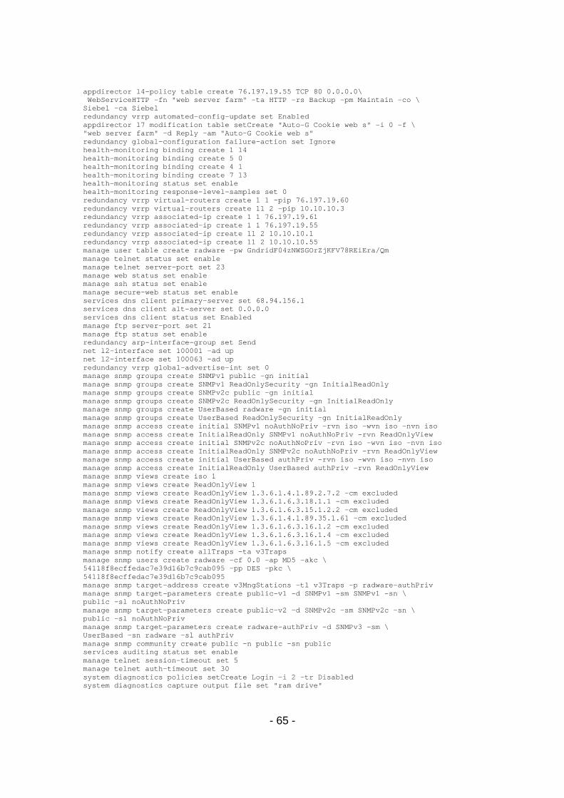
- 65 -
appdirector l4-policy table create 76.197.19.55 TCP 80 0.0.0.0\ WebServiceHTTP -fn "web server farm" -ta HTTP -rs Backup -pm Maintain -co \ Siebel -ca Siebel redundancy vrrp automated-config-update set Enabled appdirector l7 modification table setCreate "Auto-G Cookie web s" -i 0 -f \ "web server farm" -d Reply -am "Auto-G Cookie web s" redundancy global-configuration failure-action set Ignore health-monitoring binding create 1 14 health-monitoring binding create 5 0 health-monitoring binding create 4 1 health-monitoring binding create 7 13 health-monitoring status set enable health-monitoring response-level-samples set 0 redundancy vrrp virtual-routers create 1 1 -pip 76.197.19.60 redundancy vrrp virtual-routers create 11 2 -pip 10.10.10.3 redundancy vrrp associated-ip create 1 1 76.197.19.61 redundancy vrrp associated-ip create 1 1 76.197.19.55 redundancy vrrp associated-ip create 11 2 10.10.10.1 redundancy vrrp associated-ip create 11 2 10.10.10.55 manage user table create radware -pw GndridF04zNWSGOrZjKFV78REiEra/Qm manage telnet status set enable manage telnet server-port set 23 manage web status set enable manage ssh status set enable manage secure-web status set enable services dns client primary-server set 68.94.156.1 services dns client alt-server set 0.0.0.0 services dns client status set Enabled manage ftp server-port set 21 manage ftp status set enable redundancy arp-interface-group set Send net l2-interface set 100001 -ad up net l2-interface set 100063 -ad up redundancy vrrp global-advertise-int set 0 manage snmp groups create SNMPv1 public -gn initial manage snmp groups create SNMPv1 ReadOnlySecurity -gn InitialReadOnly manage snmp groups create SNMPv2c public -gn initial manage snmp groups create SNMPv2c ReadOnlySecurity -gn InitialReadOnly manage snmp groups create UserBased radware -gn initial manage snmp groups create UserBased ReadOnlySecurity -gn InitialReadOnly manage snmp access create initial SNMPv1 noAuthNoPriv -rvn iso -wvn iso -nvn iso manage snmp access create InitialReadOnly SNMPv1 noAuthNoPriv -rvn ReadOnlyView manage snmp access create initial SNMPv2c noAuthNoPriv -rvn iso -wvn iso -nvn iso manage snmp access create InitialReadOnly SNMPv2c noAuthNoPriv -rvn ReadOnlyView manage snmp access create initial UserBased authPriv -rvn iso -wvn iso -nvn iso manage snmp access create InitialReadOnly UserBased authPriv -rvn ReadOnlyView manage snmp views create iso 1 manage snmp views create ReadOnlyView 1 manage snmp views create ReadOnlyView 1.3.6.1.4.1.89.2.7.2 -cm excluded manage snmp views create ReadOnlyView 1.3.6.1.6.3.18.1.1 -cm excluded manage snmp views create ReadOnlyView 1.3.6.1.6.3.15.1.2.2 -cm excluded manage snmp views create ReadOnlyView 1.3.6.1.4.1.89.35.1.61 -cm excluded manage snmp views create ReadOnlyView 1.3.6.1.6.3.16.1.2 -cm excluded manage snmp views create ReadOnlyView 1.3.6.1.6.3.16.1.4 -cm excluded manage snmp views create ReadOnlyView 1.3.6.1.6.3.16.1.5 -cm excluded manage snmp notify create allTraps -ta v3Traps manage snmp users create radware -cf 0.0 -ap MD5 -akc \ 54118f8ecffedac7e39d16b7c9cab095 -pp DES -pkc \ 54118f8ecffedac7e39d16b7c9cab095 manage snmp target-address create v3MngStations -tl v3Traps -p radware-authPriv manage snmp target-parameters create public-v1 -d SNMPv1 -sm SNMPv1 -sn \ public -sl noAuthNoPriv manage snmp target-parameters create public-v2 -d SNMPv2c -sm SNMPv2c -sn \ public -sl noAuthNoPriv manage snmp target-parameters create radware-authPriv -d SNMPv3 -sm \ UserBased -sn radware -sl authPriv manage snmp community create public -n public -sn public services auditing status set enable manage telnet session-timeout set 5 manage telnet auth-timeout set 30 system diagnostics policies setCreate Login -i 2 -tr Disabled system diagnostics capture output file set "ram drive"
- 66 -
system diagnostics capture output term set Disabled system diagnostics trace-log output file set "ram drive and flash" system diagnostics trace-log output term set Disabled system diagnostics trace-log output syslog set Disabled system diagnostics trace-log modules set HMM -st Enabled -sev Info system diagnostics capture point set both redundancy force-down-ports-time set 0 system diagnostics capture traffic-match-mode set "Inbound and Outbound" appdirector global connectivity-check tcp-timeout set 3 !File Signature: c2f60b9aed3a4f2ab689fdd07ad0b778
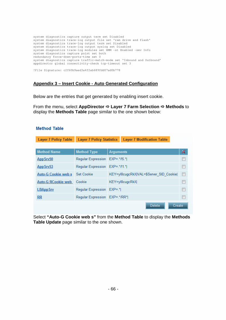
Appendix 3 – Insert Cookie - Auto Generated Configu ration
Below are the entries that get generated by enabling insert cookie. From the menu, select AppDirector ���� Layer 7 Farm Selection ���� Methods to display the Methods Table page similar to the one shown below:
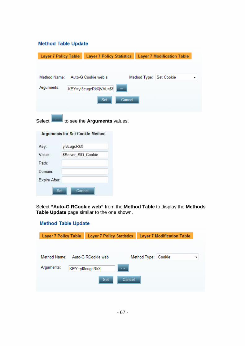
Select “Auto-G Cookie web s” from the Method Table to display the Methods Table Update page similar to the one shown.
- 67 -
Select to see the Arguments values.
Select “Auto-G RCookie web” from the Method Table to display the Methods Table Update page similar to the one shown.
- 68 -
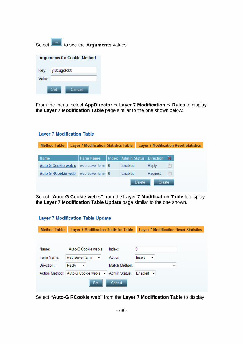
Select to see the Arguments values.
From the menu, select AppDirector ���� Layer 7 Modification ���� Rules to display the Layer 7 Modification Table page similar to the one shown below:
Select “Auto-G Cookie web s” from the Layer 7 Modification Table to display the Layer 7 Modification Table Update page similar to the one shown.
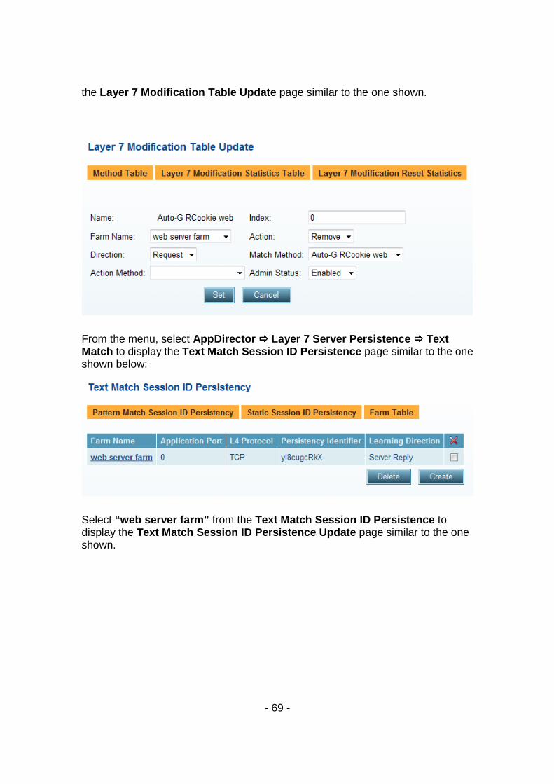
Select “Auto-G RCookie web” from the Layer 7 Modification Table to display
- 69 -
the Layer 7 Modification Table Update page similar to the one shown.
From the menu, select AppDirector ���� Layer 7 Server Persistence ���� Text Match to display the Text Match Session ID Persistence page similar to the one shown below:
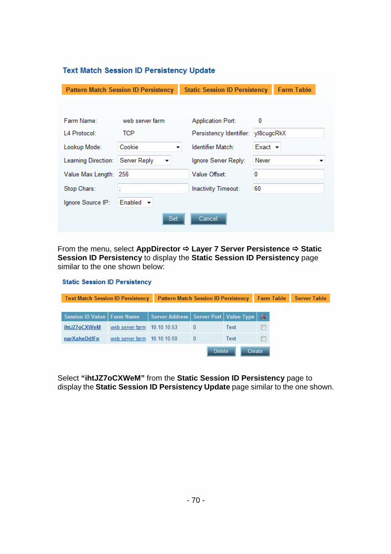
Select “web server farm” from the Text Match Session ID Persistence to display the Text Match Session ID Persistence Update page similar to the one shown.
- 70 -
From the menu, select AppDirector ���� Layer 7 Server Persistence ���� Static Session ID Persistency to display the Static Session ID Persistency page similar to the one shown below:
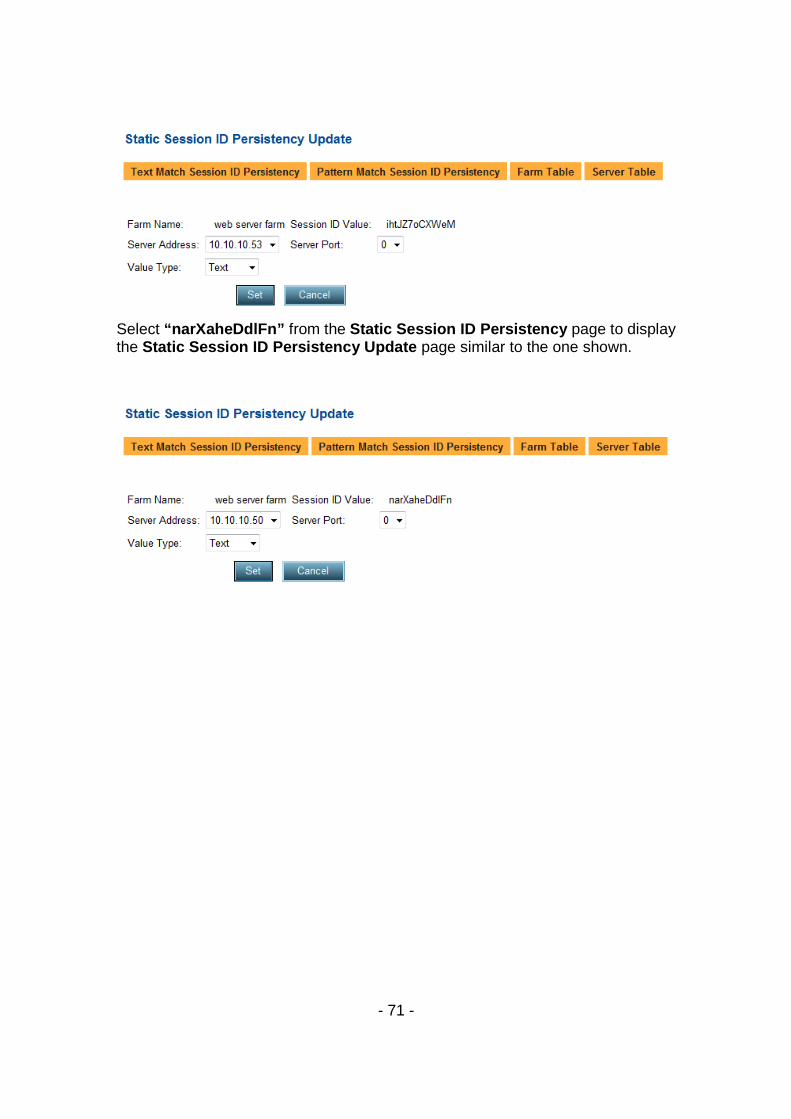
Select “ihtJZ7oCXWeM” from the Static Session ID Persistency page to display the Static Session ID Persistency Update page similar to the one shown.
- 71 -
Select “narXaheDdlFn” from the Static Session ID Persistency page to display the Static Session ID Persistency Update page similar to the one shown.
- 72 -
Technical Support Radware offers technical support for all of its products through the Radware Certainty Support Program. Please refer to your Certainty Support contract, or the Radware Certainty Support Guide available at: http://www.radware.com/content/support/supportprogram/default.asp. For more information, please contact your Radware Sales representative or: U.S. and Americas: (866) 234-5763 International: +972(3) 766-8666 © 2008 Radware, Ltd. All Rights Reserved. Radware and all other Radware product and service names are registered trademarks or trademarks of Radware in the U.S. and other countries. All other trademarks and names are the property of their respective owners.