CRITICALITY ALARM SYSTEM NFA-01 · It also displays the status of criticality alarm, EHT voltage...
18
1 CRITICALITY ALARM SYSTEM NFA-01.05
Transcript of CRITICALITY ALARM SYSTEM NFA-01 · It also displays the status of criticality alarm, EHT voltage...

1
CRITICALITY ALARM SYSTEM
NFA-01.05
2
Table of Contents
1. Criticality Alarm System NFA-01.05 ............................................................................................... 3
2. General ........................................................................................................................................... 3
2.1. System Description ................................................................................................................ 3
2.2. Main parts............................................................................................................................... 3
2.3. Common features................................................................................................................... 4
3. Detailed Description........................................................................................................................ 5
3.1. Criticality Monitor (CM) unit NFA-01.05-11 ........................................................................... 5
3.1.1. Detector Probes............................................................................................................. 5
3.1.1.1. Ion chamber probe NFA-01.05-11-IC ....................................................................... 5
3.1.1.2. GM probe NFA-01.05-11-GM ................................................................................... 5
3.1.2. Monitor Unit ................................................................................................................... 6
3.1.2.1. Signal Processing and Logic (SPL) .......................................................................... 6
3.1.2.2. Power supplies.......................................................................................................... 8
3.2. System Criticality Alarm unit NFA-01.05-21........................................................................... 9
3.2.1. Alarm circuit................................................................................................................... 9
3.2.2. Power supply ............................................................................................................... 10
3.2.3. Remote Console Connection ...................................................................................... 10
3.3. Data Acquisition module (Optional) ..................................................................................... 11
3.4. Mechanic .............................................................................................................................. 12
3.5. Battery Backup..................................................................................................................... 12
3.6. Remote Alarm Annunciator Unit: ......................................................................................... 13
3.7. Electronic Hooter.................................................................................................................. 15
4. Tecnical Specifications ................................................................................................................. 16
4.1. Probe characteristics............................................................................................................ 16
4.2. Monitoring unit...................................................................................................................... 17
4.3. General Characteristics........................................................................................................ 17
3
1. Criticality Alarm System NFA-01.05
NFA-01.05 Criticality Alarm System (CAS) is required for prompt detection and audiovisual alarm annunciation of criticality accidents and to raise an alert for rapid and immediate evacuation of personnel from the affected areas. The CAS shall be based on the well-known 2 out of 3 principle of detection and alarm redundancy.
2. General
2.1. System Description
The Criticality Alarm monitoring System (CAS) comprises of 3 nos. of Criticality Monitor (CM) units with detector and a System Criticality Alarm (SCA) unit.
Each CM carry out their functions like detection, data processing, display, alarm generation etc. independently and send the alarm signals to the SCA unit.
SCA unit accepts the alarm relay contacts from individual CMs and generate criticality alarm when two out of the three CMs are in alarm condition (Dose or Dose rate alarm). The SCA unit also includes a Data Acquisition and Display module (DAS). It acquires the analog values and alarm status from each CM and display on a graphic LCD display. It also displays the status of criticality alarm, EHT voltage levels, alarm settings etc. The DAS module stores the data on its local memory. The DAS module is provided with a 10/100 Mbps Ethernet port for communicating with remote host PC. The DAS provides the current data and stored data to the host PC on command. The software protocol is Modbus/RTU or Modbus/TCP. Each Criticality monitor and SCA are provided with battery backup for 8 hours. All the batteries are kept in a separate rack and wired to individual units.
2.2. Main parts
1) Criticality Monitor unit NFA-01.05-11: Three independent Criticality Monitor (CM) units measure the dose rate and dose. These modules also include alarm indication and annunciation circuitry. It generates alarm when channel says that dose exceeds 30x10-6 Gy (3 mRad) within a period of 500 ms or the dose rate exceeds 40x10-3 Gy/h (4 R/Hr) in case of fast criticality accidents. Alarms may be set anywhere over the entire operating range of the detector. Five alphanumeric LED display gives continuous update of current conditions of dose and dose rate of three channels. Visual indicators present the operational status (Abnormal, Acknowledged Abnormal, and Normal) of the channel. An alarm acknowledgment button located on the front panel allows users to reset alarm signalisation if the abnormal condition finished.
2) System Criticality Alarm unit NFA-01.05-21: System Criticality Alarm (SCA) unit generates alarm when 2 from 3 the three channels says that dose exceeds 30x10-6 Gy (3 mRad) within a period of 500 ms or the dose rate exceeds 40x10-3 Gy/h (4 R/Hr) in case of fast criticality accidents Visual and audio indicators present the operational status (Abnormal, Acknowledged Abnormal, and Normal) of the entire instrument. The SCA may include (optionally) a Data Acquisition and display module (DAS). It acquires the analog values and alarm status from each monitor and display on a Graphic LCD display. It also displays the status of criticality alarm, EHT voltage levels, alarm settings etc. The data acquisition module stores the data on its local memory. The DAS module is provided with a 10/100 Mbps Ethernet port for communicating with remote host PC.

4
The DAS provides the current data and stored data to the host PC on command. The software protocol is Modbus/RTU or Modbus/TCP.
3) Each Criticality monitor and SCA shall be provided with battery backup for 8 hours. All the batteries are kept in a separate rack and wired to individual units.
4) The electronics are enclosed in a 19” enclosure. Installation is as simple as connecting AC power.
2.3. Common features
a) The instrument is capable of continuous operation.
b) The instrument may include a DAS.
c) Acknowledge and Reset functions are activated on closing the respective switch.
d) The various components used in the monitor are easily available types. In case of custom made components, availability of spares for 10 years is guaranteed.
e) PCB-s are of industrial grade and withstand vibration / acceleration uptown 30 Hz/ 1.5g in all axes.
f) The selector switches and relays are O/E/N make with gold plated contacts.
g) All the ground potential points are wired with thick wires in star fashion to avoid potential drop.
h) The CAS monitor enclosure is able to withstand the atmospheric conditions in a radio-chemical plant.
i) The CAS monitor immune to radiated and conducted EMI.
j) The CAS monitor meets the standards IEC 860, ISO 7753, ANSI/ANS 8.3-1997.
k) The CAS monitor is provided with redundant power supplies, processing circuitry and supervisory circuitry.

5
3. Detailed Description
3.1. Criticality Monitor (CM) unit NFA-01.05-11
Each Criticality Monitor (CM) unit comprises gamma radiation detector and the associated electronics for the amplification, signal processing and alarm generation.
3.1.1. Detector Probes
There are two kinds of detector probes to sense radiations of pulse shape gamma radiation released from fission material. The NFA-01.05-11-IC probe has a gamma sensitive ionisation chamber, and NFA-01.05-11-GM has GM tubes as sensing element.
• The detector probes are located external to the monitor.
• The instrument is provided with 100 m cables between detector probes and the monitor.
• The three detector probes are housed in a wall mounted cabinet.
Detector probes by which the radiation from a criticality accident is measured consist one or more radiation detector(s) and the corresponding electronic including signal conditioning stage, HV supply, microcontroller and serial interfacing. Each detector probe has spectral balanced response to gamma radiation. The dose accumulated in successive intervals of 500 ms is computed and displayed. The probe communicates via a bi-directional line and can be connected to a computer. It is able to transmit the signal from probe to a maximum distance of 100 m.
3.1.1.1. Ion chamber probe NFA-01.05-11-IC
A CRGJ 10 (Photonis-France) ionization chamber is used for detecting gamma radiation.
The signal conditioning module shall receive the output from the detectors and condition the same for further processing. The linear DC stage is used for the measurement of currents from gamma ionisation chamber. The current from an ionisation chamber, with the values of 10-11 A to 10-3 A, is fed to the equipment. A linear DC amplifier with 8 switch able ranges converts detector signal into didital form. The range switching is accomplished by automatic manner signal. The TEST GEN. is controlled from TEST control. If this level is high, a 5 µA current is switched to the amplifier. The positive HV power supplies are built up of encapsulated circuits surrounded by current-loop driven isolated set-value controls and HV-monitoring isolation amplifiers.
3.1.1.2. GM probe NFA-01.05-11-GM
The NFA-01.05-11-GM is a highly sensitive gamma radiation meter with an extremely wide measurement range. Its case is sealed and it does not contain any manual control buttons. The device contains a special algorithm as well, which alarms in case of the significant increase of radiation level both in short or long periods of time.

6
3.1.2. Monitor Unit
3.1.2.1. Signal Processing and Logic (SPL)
Signal Processing and Logic (SPL) unit performs the following functions:
a) Interfacing with detector probe and SCA module
b) Measurement function and display of radiation dose rate and dose.
c) Alarm indication and annunciation.
d) Transmission of signals for System Criticality Alarm unit
e) Transmission of signals for remote recorder and alarm annunciator
f) Diagnostics.
Interface
The probe communicates via a bi-directional line with monitor unit. The probe communicates via a bi-directional line and can be connected to a computer. It shall be able to transmit the signal from probe to a maximum distance of 100 m. It shall be able to transmit the signal from probe to a maximum distance of 100 m.
Measurement and display stage
Measurement and display stage receives the signal from the detector probe, convert it into engineering units and display the data as follows:
Dose rate:
• Range: 10 –3 Gy/h to 10 2 Gy/h
• Display: 5-digit 12.7 mm. 7-segment LED display in engineering units.
• Sampling rate: 1 ms.
Dose:
The dose accumulated in successive intervals of 500 ms is computed and displayed as follows:
• Range: 0 to 100x10 –6 Gy
• Display: 5-digit, 12.7 mm, 7-segment LED display in engineering units.
• Update time: 500 ms (fixed).
When the measurement exceeds the range, the maximum of the range will be displayed and the display does not go blank.
Testing facilities: a suitable signal generator along with a test switch for routine testing of measurement and display module & alarm module is provided.

7
Current output: 2 nos. of 4 to 20 mA current signals equivalent to the dose and dose rate readings are terminated on the remote console connector for transmission to remote control room.
Alarm indication and annunciation module
The alarm indication and annunciation module receives the signal from the measurement and display stage and generates audio-visual alarm when the dose rate or dose exceeds the alarm set level.
The alarm levels are adjustable throughout the range and normally preset as follows:
o Dose rate (High) : 40x10 –3 Gy/h
o Dose (High): 30x10 –6 Gy within a period of 500 ms.
These individual alarms are indicated on the criticality monitor (Red LED) along with audio and corresponding relay contacts are wired to System Criticality Alarm unit (SCA) to generate criticality alarm.
The instrument also is provided with the following alarms:
o Dose rate (Low): Adjustable (for ensuring the proper functioning of detector and electronics circuit.)
o EHT Fail: Alarm when EHT voltage fails or drops below the set voltage.
o Battery Low: Alarm when the battery voltage is low.
These individual alarms are indicated on the criticality monitor (Red LED) along with audio and corresponding relay contacts shall be wired to System Criticality Alarm unit (SCA).
These alarms are acknowledgeable from the SCA as well as from remote control room.
Alarm Indications shall be as follows:
• Visual indication: Flashing Red LED for each alarm type
• Audio indication: Pulsating tones
The monitor has a yellow LED for ”Normal operation” indication.
Alarm setting stability: Better than + /-5% over a period of six months.

8
Alarm annunciation sequence: As tabulated below.
Parameter Status Visual indication (Red LED) Audio.
Normal OFF OFF
Abormal Flashing ON
On Acknowledgement Steady Red OFF
Back to Normal Steady Red OFF
Reset on abnormal Steady Red OFF
Reset on norma OFF OFF
Alarm Relay: The alarm relays are energized in normal conditions and off during alarm conditions.
3.1.2.2. Power supplies
The unit has a high voltage power supply unit for the detector and a low voltage power supply unit, which supplies the DC, power supplies required for the unit. It is fitted with line filters to avoid line interference. The EHT outputs are adjustable and the values are readable on the instrument display. Low EHT alarm shall be provided.
Input Power: 240VAC ± 10%, 50Hz, single-phase supply..
9
3.2. System Criticality Alarm unit NFA-01.05-21
The System Criticality Alarm (SCA) unit comprises the alarm circuits and the power supplies for the operation of this module.
3.2.1. Alarm circuit
• This unit shall generate an audio visual alarm when any two out of the three Monitors are in alarm condition.
• Alarm Indications shall be as follows :
o Visual indication: Flashing Red LED
o Audio indication: Pulsating tone different from monitor alarm.
o Alarm status of individual module shall be indicated in SCA using Red LEDs.
• The unit shall have the following controls :
o Acknowledgement switch: To acknowledge the alarm in the monitors.
o Reset switch: To reset the monitor to non-alarm state
o Alarm test switch: To test the alarm circuits. It shall be a key lock switch.
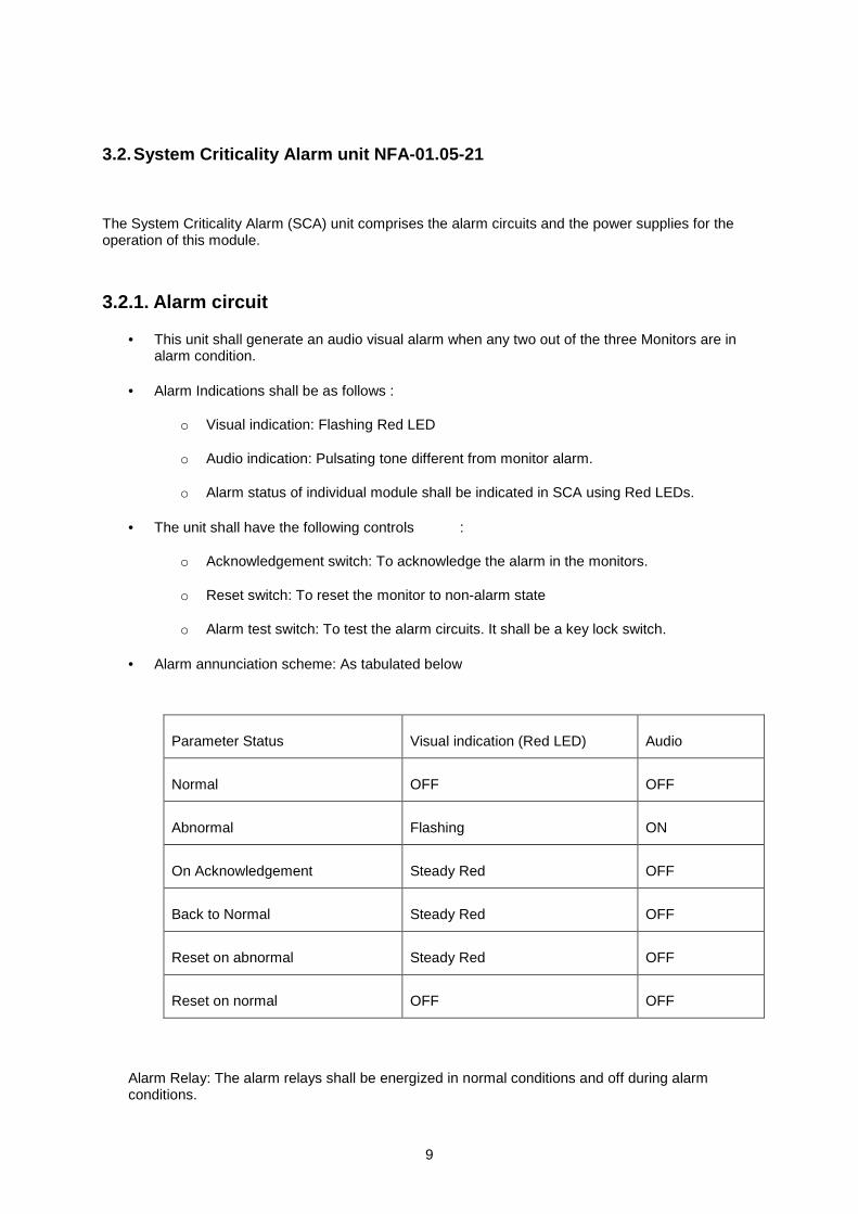
• Alarm annunciation scheme: As tabulated below
Parameter Status Visual indication (Red LED) Audio
Normal OFF OFF
Abnormal Flashing ON
On Acknowledgement Steady Red OFF
Back to Normal Steady Red OFF
Reset on abnormal Steady Red OFF
Reset on normal OFF OFF
Alarm Relay: The alarm relays shall be energized in normal conditions and off during alarm conditions.

10
3.2.2. Power supply
SCA shall have a low voltage power supply module which supplies the DC power supplies required for the Alarm circuit and DAS module. It shall have a very good line voltage and load regulation for all the supplies. It shall be fitted with Mains line filters & spike suppressors to avoid line interferences.
Input Power 240 VAC ±10%, 50Hz/ max 20 W, single-phase supply.
3.2.3. Remote Console Connection
The system shall be provided with remote console connectors for connecting to instruments in remote control room. The remote console shall be provided with the following signals.
• 4 -20 mA full scale output of Dose rate of each monitor. Output circuitry shall be able to drive 600 Ohms of load resistance.
• 4 -20 mA full scale output of Dose of each monitor. Output circuitry shall be able to drive 600 Ohms of load resistance.
• Two sets of potential free contacts of System criticality Alarm relay (Change over). Contact rating 3 Amps at 250 VAC.
• Remote alarm reset.
• Remote alarm acknowledgement.
• All these signals shall be terminated on a suitable socket (Allied Connectors). The corresponding unwired mating plug shall be supplied with the monitor.

11
3.3. Data Acquisition module (Optional)
The unit shall be provided with a data acquisition module. The DAS module shall acquire the analog data & digital data from each monitors and SCA alarm module related to dose & dose rate readings, individual monitor alarms, criticality alarm, EHT failure, Battery low, EHT voltage, alarm settings etc. These data shall be processed and displayed on a Colour LCD display in engg units. The dose and dose rate shall be displayed as trend graphs also. The refresh rate of the LCD display shall be high.
The DAS shall record the data related to dose rate & dose readings at regular interval in a local storage media. The interval shall vary from 1 msec to 1 minute. It shall also record the alarm status including the instances of alarm generation and restoration to normal state. During the alarm condition, the recording interval shall be short so that data is not lost. The monitor shall retain data for at least the previous 24 hours at any time. In case of an alarm, the data preceding to the alarm, during the alarm and after the alarm shall be retained and not overwritten. The data in memory shall be provided through Ethernet port to a remote PC on demand. The protocol shall be based on Modbus. The recording intervals shall be as follows:
Preceding the accident : 0.1 s. During first 10 seconds after criticality has been detected : 0.1 s. During the next 100 secs. : 1 s. During the next 1000 secs. : 10 s.
Computer Interface:
The DAS module shall be provided with an Ethernet 10/100 Mbps port for interfacing with a remote IBM PC-compatible computer. The PC and the instrument shall operate in a host-slave configuration and the software protocol shall be Modbus/TCP or Modbus/RTU. The PC as the host shall give commands and send queries. The monitor shall carry out the various functions as per the required information in response to the queries.
The firmware of the instrument shall be able to send the instrument data like Instrument ID, Instrument type, alarm settings, alarm status, current reading, diagnostic status of EHT etc. to the Host PC on demand. The firmware shall also send the history data for at least the last 24 hours on demand. Detailed list of the command and response for the Host-slave communication will be provided by the user.
The CAS shall have built-in self diagnostics. On being powered it shall perform tests to ensure that all components and sub systems are functioning properly . It shall check for the Power supply, High Voltage Supply, Detector, Counting and measuring circuits, Alarm Systems and Display Systems. The firmware of DAS should not halt data acquisition function any time.
12
3.4. Mechanic
Instrument Trolley:
• All the hardware like criticality monitors, System Criticality alarm unit etc may be fitted in an floor mounted type Instrument trolley made of M.S.
• The trolley shall be provided with castor wheels with locks / breaks.
• The racks shall be fitted with railings for pulling out for maintenance.
• Front and Rear sides shall have doors with locking arrangement.
• The doors shall be provided with holes with filters to facilitate air suction from surroundings.
• Sufficient Cooling fans shall be provided inside the trolley at different levels.
• Two Mains supply boards with required sockets, indicators and switches / MCBs shall be provided inside the trolley.
• One power board shall be used for fans & other utilities and the other shall be used for electronic units.
• The Trolley shall qualify minimum industrial protection Class IP-54.
• The trolley shall be Vapor-tight , rugged & elegant
230VAC +/-10%, 50Hz, single phase supply. The cabinet shall be provided with Mains power boards, Power ON/OFF switch and indicator. Independent power cables shall be provided from the cabinet to each criticality monitor and the system criticality alarm unit. Separate Power ON/OFF switch and indicators shall be provided on the modules.
3.5. Battery Backup
Sealed maintenance free Lead acid batteries shall be provided for each criticality monitor and system criticality alarm unit for operation for a minimum period of 8 hours. To protect the system against possible failure of the low voltage power supply (LVPS), lead-acid batteries ensure continuous power supply in accordance with the specified standards The LVPS of the monitors and SCA rack shall be capable of charging the batteries in trickle and boost mode.
The system shall give distinct audio/visual alarm when the system switch over from mains to battery and the visual alarm should be ON as long as the system is working on battery.
The batteries shall be housed in separate rack mounted in the instrument trolley. They shall be wired to corresponding racks.

13
3.6. Remote Alarm Annunciator Unit:
The Criticality alarm system shall be supplied with a remote alarm annunciator unit and a hooter for indicating alarm status of the system at a remote location.
No. Of channels : 2
Technology : CMOS based
Facia : Two windows replaceable from front.
Window : 70mm (W) x 50mm (H), Superbright Red LEDs
Alarm Input : NO/NC type potential free contacts , configurable
Input protection : Opto isolated
Response Time : Less than 25 mSec
Interrogation voltage : +24 V DC
Alarm indication : Visual alarm on windows and audio alarm
Audio output : Opto isolated relay contact for hooter
:Contact rating of 230V AC, 6A
Visual alarm Flash rate : 60 flashes/min. (Fast) and 30 flashes/min. (Slow)
Control switches : Test, Ack, Reset as external switches.
Alarm Sequence : ISA -18.1 standard SEQUENCE M (Manual reset)

14
Sequence Table (Sequence M):
S.l. No.
PROCESS CONDITION
PUSHBUTTON OPERATION
SEQUENCE STATE
VISUAL DISPLAY
ALARM AUDIBLE DEVICE
REMARKS
1 NORMAL - NORMAL OFF SILENT
2 ABNORMAL - ALARM FLASHING AUDIBLE LOCK-IN
3 ABNORMAL/ NORMAL
ACKNOW. ACKNOW. ON SILENT MAN. RESET REQUIRED
4A ABNORMAL RESET TO LINE 3
4B NORMAL NORMAL OFF SILENT MAN. RESET
Power supply 230V AC ± 10% , 50Hz
Mains ON Indication There shall be an LED indication on the front facia for mains ON.
Ambient Conditions Temperature : 0 -55 deg C Humidity : 5 -95 % RH
Mounting Panel Mounting. Mounting accessories shall be provided.
Input /Output Terminations The input connections shall be terminated on a high quality detachable type terminal block Model Combicon of Pheonix Make

15
3.7. Electronic Hooter
Input : Potential free contact (one)
Output : 10W PMPO
Sound Type : Normal / Intermittent ( selectable)
Adjustment : Volume & Tone shall be adjustable by pots.
Anti-humidity treatment : Acryform conformal coating on PCB
Power Fuse : 1A
Response time : With in 1 Second.
Power Supply : 230 V AC +/-10 % , 50 Hz / 24V DC selectable.
Housing : Extruded Aluminium
Ambient Conditions : Temperature : 0 -55 deg C, Humidity : 5 -95 % RH
Mounting : Flush Panel / Wall mounted. Mounting accessories shall be provided

16
4. Tecnical Specifications
4.1. Probe characteristics
Detector GM tubes in probe NFA-01.05-01-GM
Ion chamber in probe NFA-01.05-01-IC
• Type: CRGJ 10 (Photonis-France) ionization chamber for detecting Gamma radiation.
• Gas filling: Xenon, 700 kPa (Other filling gases and/or pressures are available)
• Gamma Sensitivity: 5 x 10⁻¹⁰ A/R•h-1 (5 x 10⁻⁸ A/Gy•h-1)
Measuring range Dose rate: 10 –3 Gy/h to 10 2 Gy/h (10 –1 R/h to 10 4 R/h) (Sampling rate: fixed 1 ms) (linear response and non saturation).
Dose: 0 to 100x10 –6 Gy (0 to 10 mRad.) (Update time: fixed 500 ms).
Energy response ± 35 % over the range of 0.1 MeV to 3 MeV
Alarm levels Dose rate: 40x10 –3 Gy/h (4 R/h). Adjustable.
Dose: 30x10 –6 Gy (3 mRad). Adjustable.
Time to alarm 200 ms (at radiation of twice the alarm set point)
Monitoring radius 30 m in the air for a threshold of 250 x 10 -6 Gy
Communication with monitor unit
RS 485
Transferred information: Dose rate, Dose, HV settings, Testing, Watch Dog
Dimensions Length 510 mm,
Diameter 100 mm
Mass 2 kg.

17
4.2. Monitoring unit
Input Power 240 VAC ±10%, 50Hz/ max 20 W, single-phase supply.
Weight max. 1 kp.
Dose rate:
• Display: 5-digit 12.7 mm. 7-segment LED display in engineering units.
• Time Constant/update Time: Automatically variable from 0.01 s to 30 s. Inversely proportional to the measured value.
• When the measurement exceeds the range, the maximum of the range may be displayed and the display should not go blank.
• Testing facilities: a suitable signal generator along with a test switch for routine testing of measurement and display module & alarm module shall be provided.
4.3. General Characteristics
Reliability: Excellent due to use of selected components and redundancies. The MTBF is higher than 7 years (except for the optional PC computer).
Maintainability: Processing and alarm circuitry has been designed so to allow their replacement when powered, without interruption of the supervising mission
Supervision. The graphic interface allows real time (or delayed time) knowledge of: -Data status for each probe -Probe parameters -History of the events
Environment Operating Temperature: 0 to 50 ºC operation Operating Humidity 0 % to 90 % RH, non-condensing The instrument enclosure and detector assembly shall comply with IP-54. Electronic units shall withstand cumulative radiation dose of 10000 Rad. (30 years of operation).
Alarm indication: Audible 2 tones siren (800 Hz and 1000 Hz ) / 100 dB at 1 m
Visual: 2 flash-lights / 5 joules power

18