Critical Design Review AAE451 – Team 3 Project Avatar December 9, 2003 Brian Chesko Brian Hronchek...
113
Critical Design Review AAE451 – Team 3 Project Avatar December 9, 2003 Brian Chesko Brian Hronchek Ted Light Doug Mousseau Brent Robbins Emil Tchilian
-
date post
19-Dec-2015 -
Category
Documents
-
view
214 -
download
0
Transcript of Critical Design Review AAE451 – Team 3 Project Avatar December 9, 2003 Brian Chesko Brian Hronchek...

Critical Design Review
AAE451 – Team 3
Project Avatar
December 9, 2003Brian CheskoBrian HronchekTed LightDoug MousseauBrent Robbins Emil Tchilian

2
AAE 451Team 3Team 3ProjectProject AvatarAvatar Aircraft Name
Avatar
av·a·tar - n. - 1. <chat, virtual reality> An image representing a user in a multi-user virtual reality.
Source: The Free On-line Dictionary of Computing
http://wombat.doc.ic.ac.uk/foldoc/
3
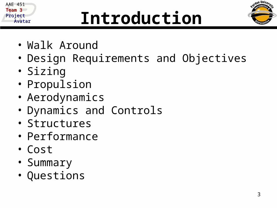
AAE 451Team 3Team 3ProjectProject AvatarAvatar Introduction
• Walk Around• Design Requirements and Objectives• Sizing• Propulsion• Aerodynamics• Dynamics and Controls• Structures• Performance• Cost• Summary• Questions
4
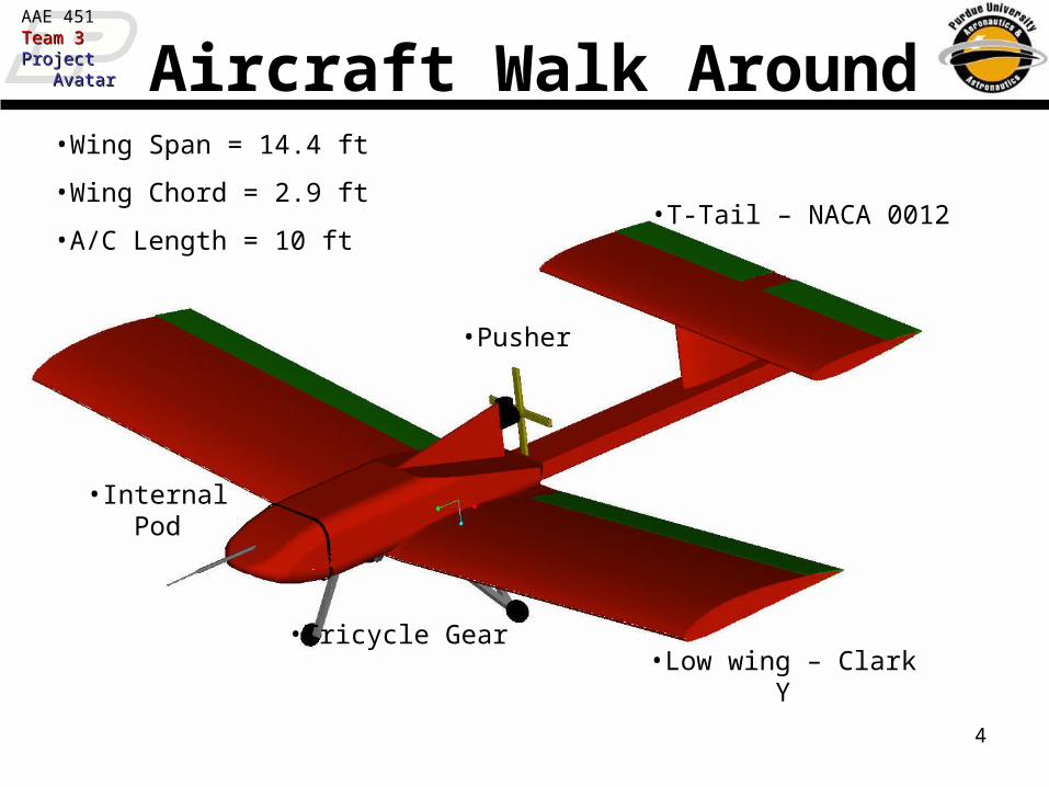
AAE 451Team 3Team 3ProjectProject AvatarAvatar Aircraft Walk Around
•Low wing – Clark Y•Tricycle Gear
•T-Tail – NACA 0012
•Pusher
•Wing Span = 14.4 ft
•Wing Chord = 2.9 ft
•A/C Length = 10 ft
•Internal Pod

5
AAE 451Team 3Team 3ProjectProject AvatarAvatar Design Requirements & Objectives
• Maximum weight < 55 lbs
• Cruise speed > 50 ft/sec
• Stall speed < 30 ft/sec
• Climb angle > 5.5°
• Operating ceiling > 1000 ft
• Flight time > 30 minutes
• Payload of 20 lbs in 14”x6”x20” pod
• Carry pitot-static boom
• Spending limit < $300
• T.O. distance < 106 ft (~60% of McAllister Park runway length)
• Rough field capabilities
• Detachable wing
• Easy construction

6
AAE 451Team 3Team 3ProjectProject AvatarAvatar Constraint Diagram
Aircraft Constraint Diagram
0
4
8
12
16
20
24
28
32
36
40
0 0.25 0.5 0.75 1 1.25 1.5 1.75 2
W/S (lbf/ft^2)
W/P
(lb
f/sh
p)
Cruise Speed
Stall Speed
Climb
T/O dist
Landing dist
Ceiling
Endurance
Minimum Structure
Minimum Power
Power Loading = 15.5 lbf/shpWing Loading = 1.28 lbf/ft^2

7
AAE 451Team 3Team 3ProjectProject AvatarAvatar Propulsion
8
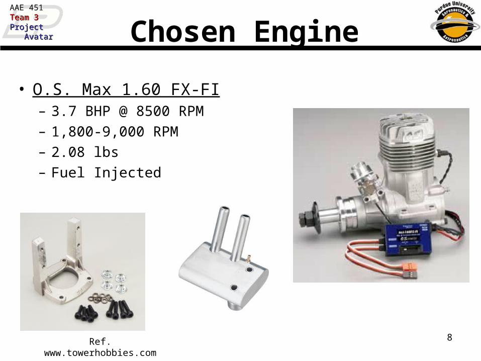
AAE 451Team 3Team 3ProjectProject AvatarAvatar Chosen Engine
• O.S. Max 1.60 FX-FI– 3.7 BHP @ 8500 RPM– 1,800-9,000 RPM– 2.08 lbs– Fuel Injected
Ref. www.towerhobbies.com
9
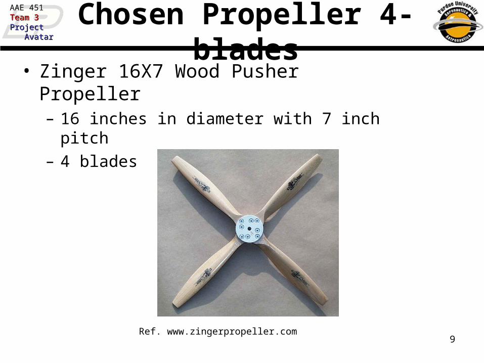
AAE 451Team 3Team 3ProjectProject AvatarAvatar Chosen Propeller 4-blades• Zinger 16X7 Wood Pusher Propeller
– 16 inches in diameter with 7 inch pitch– 4 blades
Ref. www.zingerpropeller.com

10
AAE 451Team 3Team 3ProjectProject AvatarAvatar Chosen Fuel Tank
• Fuel tank chosen is:– Du-Bro 50 oz. fuel
tank– Available from
Tower Hobbies– Located at the C.G.
of aircraft– Good for up to 32
min. of flight time (when completely full).
34 ( )
8in deep
13 ( )
2in
38 ( )
8in
Ref. www.towerhobbies.com

11
AAE 451Team 3Team 3ProjectProject AvatarAvatar Takeoff EOM Integration
WDTag
W
ThrustDrag + Rolling Friction
0 20 40 60 80 100 1200
5
10
15
20
25
30
35
Position [ft]
Vel
ocity
[ft
/s]
Velocity vs. Position at Takeoff
Position [ft]
Vel
ocity
[ft/s
]
Velocity vs. Position at Takeoff
Takeoff Distance Within Constraint

12
AAE 451Team 3Team 3ProjectProject AvatarAvatar Max Velocity
30 40 50 60 70 80 90 1000
2
4
6
8
10
12
14
16
18
20
Flying Velocity [ft/s]
Th
rust
/Dra
g [
lbf]
Maximum Velocity
Thrust
Drag
13
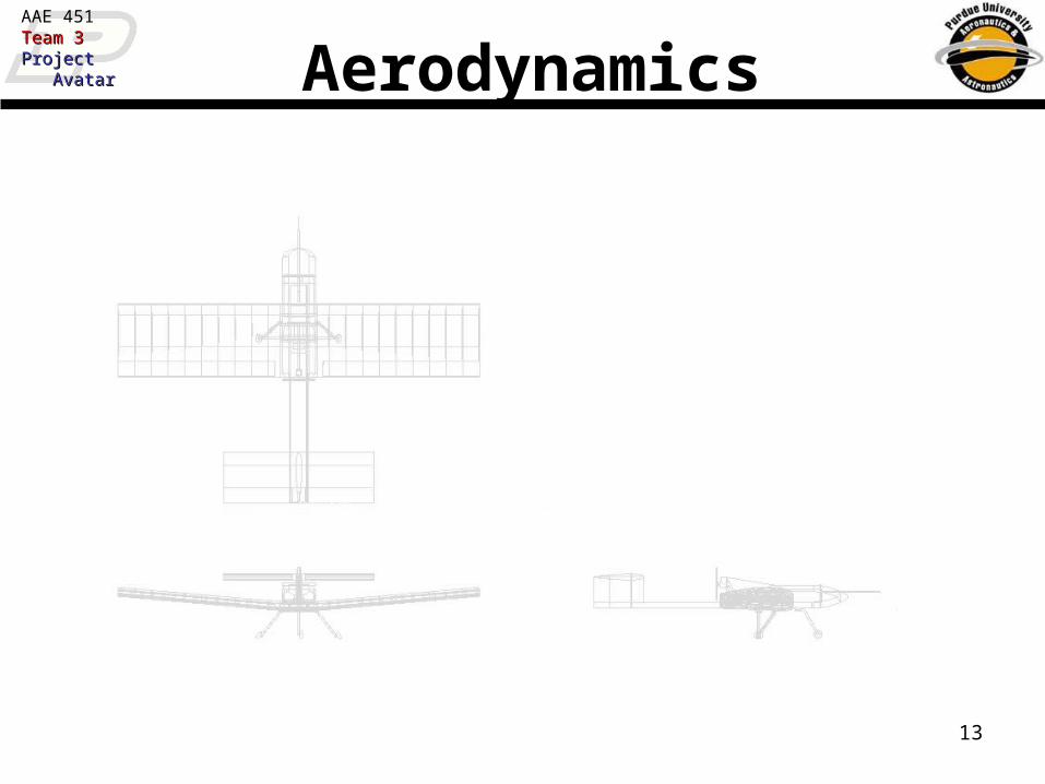
AAE 451Team 3Team 3ProjectProject AvatarAvatar Aerodynamics

14
AAE 451Team 3Team 3ProjectProject AvatarAvatar Wing Dimensions
• Prandtl’s Lifting line theory used for aerodynamic modeling of the lifting components• Input parameters: AR, a0, L=0, .
• Lifting Line Model Gives CL, CDi at prescribed • CDvisc found using Xfoil which was used to obtain
CD = CDi+CDvisc
5° Dihedral

15
AAE 451Team 3Team 3ProjectProject AvatarAvatar
-1 -0.5 0 0.5 1 1.50.005
0.006
0.007
0.008
0.009
0.01
0.011
0.012
0.013
0.014
0.015
Section Lift Coefficient, cl
Sec
tion
Dra
g C
oeff
icie
nt,
c d
Drag Polar for Candidate Airfoils
NACA 441244154425241823018ClarkY
Airfoil Selection
Region of Interest
Clark Y Airfoil has low drag over range of interest
Clark Y

16
AAE 451Team 3Team 3ProjectProject AvatarAvatar
-10 -8 -6 -4 -2 0 2 4 6 8 10-1
-0.5
0
0.5
1
1.5
2
Angle of Attack
Sec
tion
Lift
Coe
ffic
ient
, c l
-1 -0.5 0 0.5 1 1.5 20.005
0.01
0.015
0.02
0.025
0.03
0.035
0.04
0.045
0.05
Section Lift Coefficient, cl
Sec
tion
Dra
g C
oeff
icie
nt,
c d
Airfoil SelectionClark Y Airfoil
-0.2
-0.1
0
0.1
0.2
0 0.1 0.2 0.3 0.4 0.5 0.6 0.7 0.8 0.9 1
X/C
Y/C
Section Lift Coefficient Cl
Se
ctio
n D
rag
Co
eff
icie
nt
Cd
Angle of Attack (AOA)
Se
ctio
n L
ift C
oe
ffic
ien
t C
l

17
AAE 451Team 3Team 3ProjectProject AvatarAvatar Wing Stall Performance
• CL needed = 1.19• Wing without flaps
reaches CL at =13°• Wing stall possible • Wing with 15° flap
deflection reaches CL at 11°
-10 -5 0 5 10 15-0.4
-0.2
0
0.2
0.4
0.6
0.8
1
1.2
1.4CL vs aoa for different flap deflections
aoa (deg)
CL
CL no flapCL 10 deg flapCL 15 deg flap Required CL
Flaperons necessary to meet stall requirements
CL
Angle of Attack (degrees)

18
AAE 451Team 3Team 3ProjectProject AvatarAvatar Wing Performance
-0.4 -0.2 0 0.2 0.4 0.6 0.8 1 1.2 1.40
0.02
0.04
0.06
0.08
0.1
0.12
0.14CD vs CL for different flap deflections
CL
CD
CDvsCL no flapCDvsCL 10 deg flapCDvsCL 15 deg flap
Required CL at stall
C D
CL

19
AAE 451Team 3Team 3ProjectProject AvatarAvatar Drag Build Up At Cruise
Component CD Drag
Wing 0.018 2.6 lbf
Fuselage 0.0045 0.6 lbf
Horizontal Tail
0.0043 0.6 lbf
Vertical Tail 0.0017 0.04 lbf

20
AAE 451Team 3Team 3ProjectProject AvatarAvatar Wing Operating Parameters
CL(of wing)
Flaperon Deflection
CD L/D
Stall 1.19 11° 15° 0.119 10
T/O 0.989 8° 15° 0.084 12
Cruise 0.44 2.8° 0° 0.018 24

21
AAE 451Team 3Team 3ProjectProject AvatarAvatar Dynamics and Controls

22
AAE 451Team 3Team 3ProjectProject AvatarAvatar Center of Gravity & Aerodynamic Center
• Aircraft Center of Gravity is 3.2 ft from nose.– Calculated from CAD program Pro-E
• Aircraft Aerodynamic Center is 3.7 ft from nose.– Position where pitching moment of aircraft doesn’t change with
angle of attack– Calculated using Lift from Wing and Horizontal Tail
Center of Gravity
Aerodynamic Center

23
AAE 451Team 3Team 3ProjectProject AvatarAvatar Static Margin
8 9 10 11 12 13 14 152.8
3
3.2
3.4
3.6
3.8
4
Horizontal Tail Area (ft2)
Dis
tanc
e fr
om N
ose
of A
ircra
ft =
> x
(ft)
Position on Aircraft vs. Horizontal Tail Area
Aerodynamic Center of Aircraft
Static Margin = 20%
Static Margin = 15%
Center of Gravity
15% 20%
ac cg
wing
X XSM
c
• Desired Static Margin is 15% - 20%– Dependent on C.G. and A.C. location
• Static Margin is 15%• Contributes to
Horizontal Tail Sizing
24
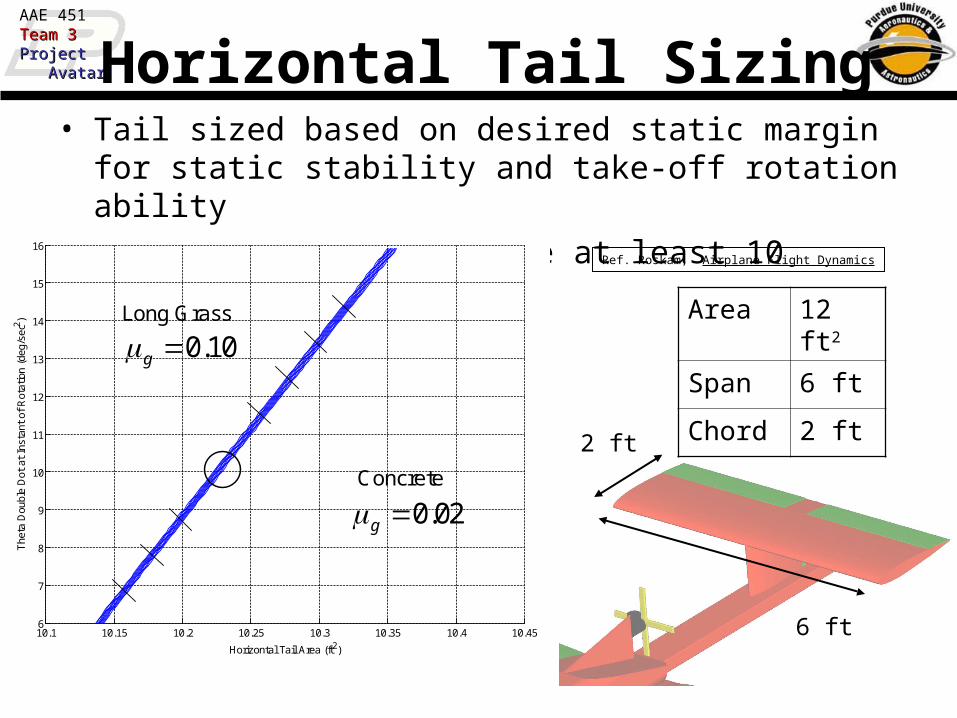
AAE 451Team 3Team 3ProjectProject AvatarAvatar Horizontal Tail Sizing
• Tail sized based on desired static margin for static stability and take-off rotation ability double-dot should be at least 10 deg/sec2
Area 12 ft2
Span 6 ft
Chord 2 ft
6 ft
2 ft
10.1 10.15 10.2 10.25 10.3 10.35 10.4 10.456
7
8
9
10
11
12
13
14
15
16
The
ta D
oubl
e D
ot a
t In
stan
t of
Rot
atio
n (d
eg/s
ec2 )
Horizontal Tail Area (ft2)
Concrete
Long Grass
0.02g
0.10g
Ref. Roskam, Airplane Flight Dynamics

25
AAE 451Team 3Team 3ProjectProject AvatarAvatar Vertical Tail Sizing
• Value of yawing coefficient due to sideslip angle should be approximately 0.001 = 10e-4
• Tail area should be ~2 ft2
0 0.5 1 1.5 2 2.5 3-5
0
5
10
15
20x 10
-4
Vertical Tail Area (ft2)
CN
b [de
g- 1]
Coefficient of Yaw Moment due to Sideslip vs Vertical Tail Area
Area 2 ft2
Span 1 ft
Chord 2 ft
1 ft2 ft
Ref. Roskam, Airplane Design

26
AAE 451Team 3Team 3ProjectProject AvatarAvatar Dihedral Angle
Recommendations• Survey of Roskam data on homebuilt &
agricultural low-wing aircraft: ~5°• “Wing and Tail Dihedral for Models” - McCombs
– RC w/ailerons (for max maneuverability, low wing): 0-2° EVD (Equivalent V-Dihedral ≈ dihedral)
– Free Flight Scale model low wing: 3-8° EVD
5° dihedral is a good compromise

27
AAE 451Team 3Team 3ProjectProject AvatarAvatar Control Surface Sizing
• Sizes calculate from traditional lifting device percentages.
Flaperon Elevator Rudder
Chord 0.58 ft 0.6 ft 0.6 ft
Inboard Position 0.95 ft 0.2 ft 0.1 ft
Outboard Position 7.2 ft 3 ft 1 ft
Ref. Roskam, Airplane Design
6.25 ft
2.8 ft
0.58 ft
0.6 ft
0.6 ft
0.9 ft

28
AAE 451Team 3Team 3ProjectProject AvatarAvatar
-8 -6 -4 -2 0 2 4 6 8 10 12-0.6
-0.4
-0.2
0
0.2
0.4
0.6
0.8
1
1.2
Alpha of Aircraft
Cm
of
Airc
raft
C.G
.
Cm of Aircraft vs. Alpha of Aircraft at Cruise with 0 Degree Flaperon Deflection
Elevator Deflection = -25 [degrees]-20-15-10-505
Trimming• Incidence of Horizontal Tail calculated from trimmed
flight during cruise (0 Angle of Attack)• Analysis set
incidence at
-2

29
AAE 451Team 3Team 3ProjectProject AvatarAvatar Structures

30
AAE 451Team 3Team 3ProjectProject AvatarAvatar Wing Spar Design
2 Spar Design (at .15 & .60 chord):
• Resist Bending
• Assuming 5-g loading
• 53 lbf weight
• Safety factor of 1.5
• Resist Torsion
• Less than 1o twist at tip under normal flight conditions
Spar Results:
• Material of Choice: Bass or Spruce Wood
• Front Spar:
• 3.6” high (based on airfoil)
• 0.37” thick (0.73” at root)
• Rear Spar:
• 3” high (based on airfoil)
• 0.16” thick (0.25” at root)

31
AAE 451Team 3Team 3ProjectProject AvatarAvatar Longitudinal Beam Design
2 Beam Design:
• Resist Bending from:
• 20 lbf payload
• Horizontal tail loads
• Resist Torsion from:
• Rudder deflections
• Prop wash over tail
Beam Results:
• Material of Choice: Bass or Spruce Wood
• Beam Dimensions:
• 3” high
• 0.25” thick
• 8” between the beams

32
AAE 451Team 3Team 3ProjectProject AvatarAvatar Tail Structures
• Horizontal and vertical tails comprised of carbon fiber w/ foam core
• Possible to make two foam cores, and cure entire tail at one time
• Control surfaces just need to be cut out of tail structure
• Tail spars allow attach points and transfer load to beams
Foam core with carbon fiber shell

33
AAE 451Team 3Team 3ProjectProject AvatarAvatar Rear Gear Design
• Blue lines represent pin joints
• Black tie-downs absorb energy from landing
• Up to a 33 ft/sec “crash” from 5 feet high
• Need 18” relaxed length tie-down
• Square aluminum tube transfers landing load to tie-downs and surrounding structure
• 1” x 1” x 0.065” thick – 6063-T6

34
AAE 451Team 3Team 3ProjectProject AvatarAvatar Front Gear Design
Elastic Band & Nylon Bolt
• Elastic Band Absorbs some energy from landing
• Nylon bolt breaks during hard landing
Aluminum Bolt
•Provides pivot for gear (does not break)
Front Gear Aluminum Tube
• Designed not to break
• Designed not to bend
• Al tube:
1” x 1” x 0.065” thick 6063-T6

35
AAE 451Team 3Team 3ProjectProject AvatarAvatar Other Odds and Ends
• Covering for Wing:– Coverite 21st Century Iron
on Fabric– 0.34 oz/ft2
– Stronger, and resists tears better than MonoKote
• Covering for Fuselage:– Fiberglass
• Either mold or foam core• Not conductive – won’t
interfere with internal electronics
Ref. www.towerhobbies.com

36
AAE 451Team 3Team 3ProjectProject AvatarAvatar Final Weight Estimate
Part Description Weight (lbf)Propulsion 50 oz fuel tank 0.38
O.S. 1.60 FX 2.04Sliencer E-5010 0.66Fuel (30 min. based on O.S. info) 2.2016X7 4-Blade Prop 0.47
Structures Bass/Spruce Wing Spars 4.4021st Century Fabric 1.74Ribs 0.70Bass/Spruce Tail Beam 2.15Fuselage Skin (1 ply of E-glass) 2.78V-Stab Foam Core 0.55H-Stab Foam Core 2.77V-Stab Carbon Fiber Covering (1 ply Carbon-Fiber) 0.37H-Stab Carbon Fiber Covering (1 ply Carbon-Fiber) 1.69Engine Supports 0.15Tail Spars 0.35
Landing Gear Rear Gear 2.90Front Gear 0.42Smooth Wheels 4" 0.61Bungees 0.20
Electronics Pod 20.009 channel R149DP PCM 0.08MP-2000 (includes all components) 0.40Servos - S3104 1.26Wires 0.25Battery for Receiver FUTM 1280 0.50
Miscellaneous 3.00
Total 53.01

37
AAE 451Team 3Team 3ProjectProject AvatarAvatar Performance

38
AAE 451Team 3Team 3ProjectProject AvatarAvatar Aircraft Performance
PARAMETER VALUE (Approx)Endurance (at cruise) 30 minRange (at cruise) 17 milesMinimum Flight Velocity 30 ft/secRate of Climb (at takeoff conditions) 7.5 ft/secMaximum Velocity 90 mphClimb Angle 13.1 deg
90 ft/sec
(with 2.2lbf fuel)

39
AAE 451Team 3Team 3ProjectProject AvatarAvatar Cost

40
AAE 451Team 3Team 3ProjectProject AvatarAvatar Airframe Cost
Part Description Brand Quantity Cost/unit Total CostBass/Spruce Wing Spars n/a 2 $15.00 $30.0021st Century Fabric Coverite 4 $39.99 $159.96Ribs n/a 21 $0.98 $20.58Bass/Spruce Tail Beam n/a 2 $10.00 $20.00Fuselage Skin (1 ply of E-glass) n/a HAVEV-Stab Foam Core n/a 1 $15.00 $15.00
H-Stab Foam Core n/a 2 $15.00 $30.00V-Stab Carbon Fiber Covering (1 ply) n/a HAVEH-Stab Carbon Fiber Covering (1 ply) n/a HAVEEngine Supports n/a 1 $5.00 $5.00Tail Spars 2 $5.00 $10
Rear Gear n/a 4 $4.74 $18.96
Front Gear n/a 1 $4.74 $4.74Smooth Wheels 4" Sullivan Skylite 3 $12.39 $37.17Bungees Tool Shop 2 $1.50 $3.00Misc (Bolts, Nuts, Washers, etc) $25.00
TOTAL $379.41

41
AAE 451Team 3Team 3ProjectProject AvatarAvatar Electronics Cost
Part Description Brand Quantity Cost/unit Total CostPOD 1Onboard Laptop Computer Dell Latitude C610 1 $2,566.80 $2,566.80MIDG 1 $6,750.00 $6,750.00MIDG Power Supply uINS Power Supply 1 not determinedCamera Canon PowerShot G5 1 $1,500.00 $1,500.00
National Instrument PCMCIA DAQ Card Enterasys (CSICD-AA-128) 1 $1,195.00 $1,195.00
Wireless Network Card CSICD-AA-128 1 $80.00 $80.00Vehicle Mount Antenna -- Enterasys CSIES-AA-M05 1 $85.00 $85.00Vehicle Mount Antenna Cable CSIES-AA-PT250 1 $65.00 $65.00Range Extending Antenna CSIBB-IA 1 $80.00 $80.00AVIONICS
9 Channel R149DP PCM (Included w/Trans) Futaba 1 $139.95 $139.95
MP-2000 (includes all components) Micropilot HAVEServos - S3104 Futaba 6 $32.99 $197.94Wires 6 $4.00 $24.00Battery for Receiver FUTM Futaba 1 $44.99 $44.99
TOTAL $12,728.68

42
AAE 451Team 3Team 3ProjectProject AvatarAvatar Propulsion Cost
Part Description Brand Quantity Cost/unit Total Cost50 oz fuel tank Dubro 1 $11.49 $11.49O.S. 1.60 FX-FI O.S. 1 $714.99 $714.99Sliencer E-5010 Bisson-Pitts 1 $49.99 $49.99Engine Mount O.S. 1 $26.99 $26.9916X7 4-Blade Prop Zinger 1 $54.60 $54.60
TOTAL $858.06

43
AAE 451Team 3Team 3ProjectProject AvatarAvatar Total Aircraft Cost
What Purdue Will Pay For This Project
Airframe Cost $379.41Electronics Cost $12,728.68Propulsion Cost $858.06
TOTAL $13,966.15
44
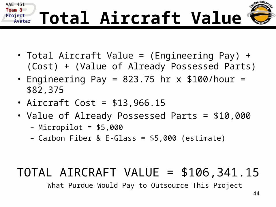
AAE 451Team 3Team 3ProjectProject AvatarAvatar Total Aircraft Value
• Total Aircraft Value = (Engineering Pay) + (Cost) + (Value of Already Possessed Parts)
• Engineering Pay = 823.75 hr x $100/hour = $82,375• Aircraft Cost = $13,966.15• Value of Already Possessed Parts = $10,000
– Micropilot = $5,000– Carbon Fiber & E-Glass = $5,000 (estimate)
TOTAL AIRCRAFT VALUE = $106,341.15
What Purdue Would Pay to Outsource This Project

45
AAE 451Team 3Team 3ProjectProject AvatarAvatar Summary

46
AAE 451Team 3Team 3ProjectProject AvatarAvatar Summary – Internal View
Camera View
Internal Pod

47
AAE 451Team 3Team 3ProjectProject AvatarAvatar Summary – 3-View

48
AAE 451Team 3Team 3ProjectProject AvatarAvatar Summary -Major Design Points
• Aircraft Description– Aspect Ratio = 5– Wing Span = 14.4 ft– Wing Area ~ 42 ft2
– Aircraft Length = 10 ft (not including air data boom)
– Engine = 3.7 hp O.S. 1.60 FX-FI – Fuel Injected
– Weight = 53 lbf
• Aircraft Configuration– T-Tail– Low Wing– Pusher– High Engine– Tricycle Gear– Internal Pod
49
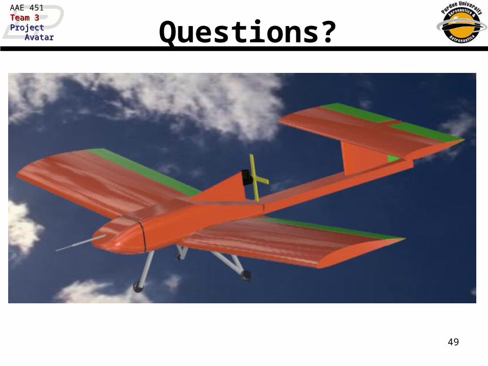
AAE 451Team 3Team 3ProjectProject AvatarAvatar Questions?

50
AAE 451Team 3Team 3ProjectProject AvatarAvatar References (I)
•[1] MATLAB. PC Vers 6.0. Computer Software. Mathworks, INC. 2001
•[2] Raymer, Daniel P., Aircraft Design: A Conceptual Approach, AIAA Education Series, 1989.
•[3] Roskam, Jan., Airplane Flight Dynamics and Automatic Flight Controls. Part I. DAR Corporation, Kansas. 2001
•[4] Gere, James M., Mechanics of Materials. Brooks/Cole, Pacific Grove, CA. 2001
•[5] Tower Hobbies. 9 December 2003. http://www.towerhobbies.com
•[6] XFoil. PC Vers. 6.94. Computer Software. Mark Drela. 2001.
•[7] Niu, Michael C., Airframe Structural Design, Conmilit Press Ltd. Hong Kong. 1995.
•[8] Halliday, et al., Fundamentals of Physics, John Wiley & Sons. New York. 1997.
•[9] Roskam, Jan, Airplane Design (Parts I-VIII), Roskam Aviation and Engineering Corp. Ottawa KS. 1988.
•[10] Kuhn, P., “Analysis of 2-Spar Cantilever Wings with Special Reference to Torsion and Load Transference”. NACA Report No. 508.
•[11] McMaster-Carr. 9 December 2003. http://www.mcmaster.com
•[12] Pro/ENGINEER. PC Release 2001. PTC Corporation.
•[13] Roskam, Jan., Methods for Estimating Stability and Control Derivatives of Conventional Subsonic Airplanes. Publisher Jan Roskam. Lawrence, KS. 1977.

51
AAE 451Team 3Team 3ProjectProject AvatarAvatar References (II)
•[14] Zinger Propeller. 9 December 2003. http://www.zingerpropeller.com
•[15] McCombs, William F., “Wing and Tail Dihedral for Models”, Model Aviation. Dec. 1994. 104-112.

52
AAE 451Team 3Team 3ProjectProject AvatarAvatar Appendix

SIZING

54
AAE 451Team 3Team 3ProjectProject AvatarAvatar Cruise Speed
S
W
CVSHP
W
S
WSHP
W
CVSHP
S
CVSHPVTP
Dcruise
p
Dcruise
p
Dcruisepout
3
3
3
out
2550)75.0(
2550)75.0(
give togrearrangin
2
1)75.0(550
gives drag thrust toequating and velocity,mes thrust ti toP Equating
)(Pr67.0
)(50
)1000(002309.0
)Aero (0275.0
3
opulsion
Andrisanis
ftV
ftft
slug
C
p
cruise
D

55
AAE 451Team 3Team 3ProjectProject AvatarAvatar Stall Speed
max2
max2
2
1
gives grearrangin and
2
1
liftfor equation with theStarting
Lstall
Lstall
CVS
W
SCVL
)(30
)(002378.0
)(2.1
3
max
Andrisanis
ftV
levelseaft
slug
flapsC
stall
L

56
AAE 451Team 3Team 3ProjectProject AvatarAvatar Climb Angle
sin Thrust
Weight
1
Lift
Drag
ThrustSHP p 550
V
)(2.1
)(30
0275.0
67.0
max flapsC
Andrisanis
ftV
C
L
stall
D
p
Weight
SHP
550 p
sin 1
C Lmax
C D
Vstall 1.1
57
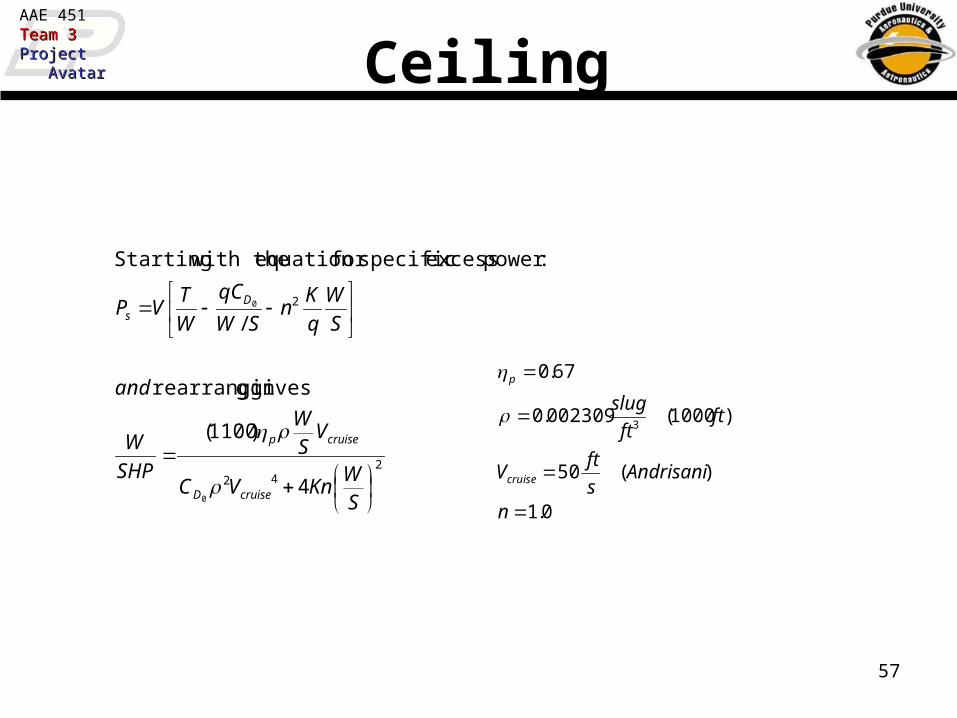
AAE 451Team 3Team 3ProjectProject AvatarAvatar Ceiling
242
2
4
)1100(
gives grearrangin
/
:power excess specificfor equation with theStarting
0
0
SW
KnVC
VSW
SHP
W
and
S
W
q
Kn
SW
qC
W
TVP
cruiseD
cruisep
Ds
0.1
)(50
)1000(002309.0
67.0
3
n
Andrisanis
ftV
ftft
slug
cruise
p

58
AAE 451Team 3Team 3ProjectProject AvatarAvatar Endurance
64.0)045.01(78.1
))((
1k
:Where
5503
4
1
2
1
:classin given equation endurance with Starting
68.0
4
3
0
0
ARe
eAR
gk
C
C
SWP
W D
Dcruise
5
025.00
AR
CD

59
AAE 451Team 3Team 3ProjectProject AvatarAvatar Takeoff
.21TOP gives TOPfor lly quadratica Solving ft. 105 iss and
009.09.4s
as 3.4)(Equation Roskamby defined is TOP where
P
W
gives Roskam from (3.2)Equation Using
2323TOG
22323TOG
23
23max /
TOPTOP
S
W
TOPCOTL
fts
RoskamCC
TOG
SL
TO
LLTO
105
98.0
)(21.1/max

60
AAE 451Team 3Team 3ProjectProject AvatarAvatar Landing Distance
25.0
2
max*/2
687.1
1265.0
:speed stallfor equation previous Inserting
265.0
:distance landingfor equation with Starting
Llanding
stalllanding
CS
WD
VD
)(002378.0
)(2.1
3
max
levelseaft
slug
flapsCL

PROP

62
AAE 451Team 3Team 3ProjectProject AvatarAvatar Appendix
• OS 1.60 FX-FI
• Consistency: The Fuel Injection system constantly supplies the correct air/fuel mixture to the engine, regardless of speed, altitude, or attitude.
• Recommended is a 450-550cc fuel tank that allows approximately 10 to 12 minute flights. = 30 min. with 50 oz. tank.

AERO

64
AAE 451Team 3Team 3ProjectProject AvatarAvatar Aerodynamic Modeling
iLl
cVaa
c
000
2
nAbVN
nn sin2)(
1
sin
sin)(
1
nnA
N
nni
Prandtl’s Lifting line theory used for aerodynamic modeling of the lifting components
Solving Prandt’s equation
Substituting:
Equation to solve:0
110 sin
sinsin
4
L
N
nn
N
nn
nnAnA
ca
b
•System of N equations with N unknowns (Solve N N matix)•Take N different spanwise locations on the wing where the equation is to be satisfied: 1, 2, .. N; (but not at the tips, so: 0 < < )•The wing is symmetrical A2, A4,… are zero
•Take only A1, A3,… as unknowns•Take only control points on half of the wing: 0 < i /2
Main Results CL = πAR*A1*(α- αLo) 0where)1(2
2
1
2
N
n
nLD A
An
A
CC
i

65
AAE 451Team 3Team 3ProjectProject AvatarAvatar Choice of main wing airfoil
From lifting line with Initial parameters:
•Rectangular planform, 1000 ft •a0 = 2pi, •αL0 = 0,•AR = 5;•W/S = 1.28 (from sizing) •CL = 0.4437
0 1 2 3 4 5 6 7 80
0.1
0.2
0.3
0.4
0.5
0.6
0.7
ClCd*10alpha
i*10
Cl distribution found at cruiseCl varies :0 to 0.58
Taking into account the Cl variation above, the need of an airfoil with a drag bucket at the specified Cl’sXfoil utilized for different foils at the above conditions

66
AAE 451Team 3Team 3ProjectProject AvatarAvatar
-1 -0.5 0 0.5 1 1.50.005
0.006
0.007
0.008
0.009
0.01
0.011
0.012
0.013
0.014
0.015
Section Lift Coefficient, cl
Sec
tion
Dra
g C
oeff
icie
nt,
c d
Drag Polar for Candidate Airfoils
NACA 441244154425241823018ClarkY
Airfoil Selection
Region of Interest
Clark Y Airfoil Drag Bucket location fits best
Clark Y

67
AAE 451Team 3Team 3ProjectProject AvatarAvatar ClarkY foil
-0.2
-0.1
0
0.1
0.2
0 0.1 0.2 0.3 0.4 0.5 0.6 0.7 0.8 0.9 1
x/c
y/c
-10 -5 0 5 10 15-0.5
0
0.5
1
1.5
2
-10 -5 0 5 10 15-0.5
0
0.5
1
1.5
2Cl vs aoa
aoa (deg)
Cl
no flap10deg15 degCruise
Xfoil runs of ClarkY foil
at cruise and take-off
Cruise: αL= -3.5deg
Takeoff no flap: αL= -3.8deg
Takeoff 10deg flap: αL= -7deg
Takeoff 15deg flap: αL= -7.8deg
In lifting Line Equation:
a0 – updated depending on condition
αL - updated according to above

68
AAE 451Team 3Team 3ProjectProject AvatarAvatar
Stall Performance
• CL needed = 1.19• Wing without flaps
reaches CL at 13 deg aoa
• Wing stall possible • Wing with 15 deg flap
deflection reaches CL at 11 degrees
-10 -5 0 5 10 15-0.4
-0.2
0
0.2
0.4
0.6
0.8
1
1.2
1.4CL vs aoa for different flap deflections
aoa (deg)
CL
CL no flapCL 10 deg flapCL 15 deg flap
Required CL
Flaperons necessary to meet stall requirements

69
AAE 451Team 3Team 3ProjectProject AvatarAvatar Stall Performance Drag Calculation
-0.4 -0.2 0 0.2 0.4 0.6 0.8 1 1.2 1.40
0.02
0.04
0.06
0.08
0.1
0.12
0.14CD vs CL for different flap deflections
CL
CD
CDvsCL no flapCDvsCL 10 deg flapCDvsCL 15 deg flap
Required CL
CD = 0.119 at required CL
CDtotal = CDinduced+CDvisc
CDinduced – from Lifting line
CD visc – integrated at the found Cls
-0.4 -0.2 0 0.2 0.4 0.6 0.8 1 1.2 1.4 1.60.005
0.01
0.015
0.02
0.025
0.03
0.035
cl
cd
Viscous Drag Coefficient calculaton
original datapolyfit functionvalues for our cl from polyfit funtion
70
AAE 451Team 3Team 3ProjectProject AvatarAvatar
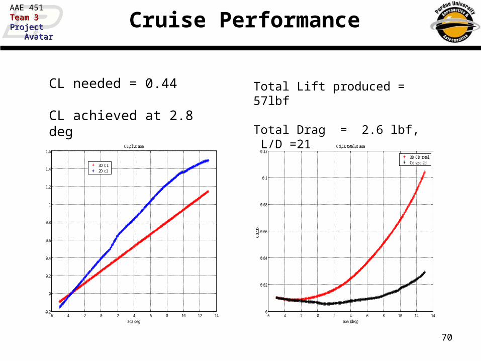
Cruise Performance
-6 -4 -2 0 2 4 6 8 10 12 14-0.2
0
0.2
0.4
0.6
0.8
1
1.2
1.4
1.6CL,cl vs aoa
aoa deg
3D CL2D cl
CL needed = 0.44 CL achieved at 2.8 deg
-6 -4 -2 0 2 4 6 8 10 12 140
0.02
0.04
0.06
0.08
0.1
0.12Cd,CDtotal vs aoa
aoa (deg)
Cd,
CD
3D CD totalCd visc 2d
Total Lift produced = 57lbf
Total Drag = 2.6 lbf, L/D =21

71
AAE 451Team 3Team 3ProjectProject AvatarAvatar
Operating Parameters
CL AoaFlap
DeflectionCD L/D
Stall 1.19 11 deg 15 deg 0.119 10
T/O 0.989 8. deg 15 deg 0.084 12
Cruise 0.44 2.8 deg 0 deg 0.018 24

D & C

73
AAE 451Team 3Team 3ProjectProject AvatarAvatar Center of Gravity
• Center of Gravity of Aircraft– Weight of Horizontal Tail changes with area
9
1i i
iAircraft
Total
W xCG
W
20.44HT HT
lbsW Area
ft
Note: 0.44 lbs/ft2 based on aircraft sizing code

74
AAE 451Team 3Team 3ProjectProject AvatarAvatar Aerodynamic Center• Aerodynamic Center as a function of Horizontal Tail
Area1
1 1
wing hh
Aircraft
h
h hac L ac
ach h
L
d SX C X
d SX
d SC
d S
Roskam Eq 11.1
ac ac wingX X c 0.49hd
d
13.6h
LC rad
Raymer Fig 16.12

75
AAE 451Team 3Team 3ProjectProject AvatarAvatar Takeoff Rotation Equation
• This sizing based on angular acceleration during take-off rotation
Ref. Roskam 421 book, pg 288-290
Variable definitions found in above reference
max
2
( ) ( ) ( )
( )( )
( )( )
g g g g g g g g
g g wf g g wf mgg g
g h g g gh gground
cg mg g cg g mg g D cg cg T
wf mg ac g cg g mg ac yy
hL h rotate ac mg g mg g cg
W x x z z D z z T z z
L x x z z M IS ft
C q x x z z

76
AAE 451Team 3Team 3ProjectProject AvatarAvatar Yaw Moment due to Sideslip
• Vertical Tail sized from Coefficient of Yaw Moment due to Sideslip
wb v
n n L V VC C C S S x b
1
0 57.3wb f sW
n n n N R f fC C C K K S l Sb
Due to Wing and Fuselage:
Roskam Eq 11.8Vol 2
Roskam Eq 10.42Vol 6
13.6v
LC rad
5.7Vx ft
241.76S ft
14.4b ft

77
AAE 451Team 3Team 3ProjectProject AvatarAvatar Dihedral Angle
EVD = A + kB
A = 0°
k = f(x/(b/2)) = 0.98
B = EVD / k ≈ EVDA=0°
B
X
CL
Ref. McCombs, William F. “Wing and Tail Dihedral for Models.”

78
AAE 451Team 3Team 3ProjectProject AvatarAvatar Dynamics
Short Period Mode
Pole -14.391 ± 1.0079i
Natural Frequency
14.431 (rad/s)
Damping Ratio
0.99721
Phugoid Mode
Pole -0.078823 ± 0.71828i
Natural Frequency
0.72259 (rad/s)
Damping Ratio
0.10908
Dutch Roll Mode
Pole -1.1607 ± 2.4427i
Natural Frequency
2.7045 (rad/s)
Damping Ratio
0.42918
Spiral Mode
Pole 0.29086
Roll Mode
Pole -25.748
Ref. Purdue University AAE565, Matlab Predator Code

STRUCTURES

80
AAE 451Team 3Team 3ProjectProject AvatarAvatar What Materials to Use
Titanium
Bass / Spruce

81
AAE 451Team 3Team 3ProjectProject AvatarAvatar Material Properties
Ref. 1999 Forest Products Laboratory Wood Handbook
Ref. www.towerhobbies.com
Titanium = difficult to obtain
Wood = not difficult to obtain
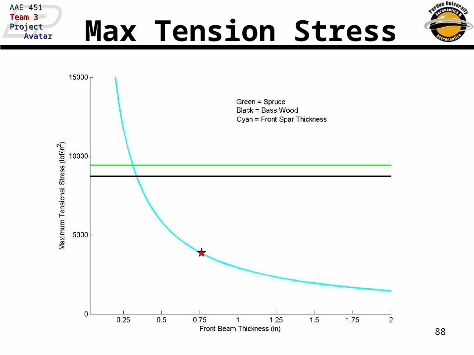
Young's Modulus Torsional Stiffness Max Compression Stress Max Tension Stress [E] (psi) [G] (psi) [syc] (psi) [syt] (psi)
Bass 1.46E+06 2.92E+05 4730 8700Spruce 1.43E+06 2.86E+05 5180 9400

82
AAE 451Team 3Team 3ProjectProject AvatarAvatar Twist Constraint (<1o)
-1.5
-1
-0.5
0
0.5
1
1.5
0 0.5 1 1.5 2 2.5 3
X (ft)
Y (
ft)
Forward Spar
Rear Spar
Rib
Rib Cap (not shown)
Rib Rib
Chord-wise Lift Resultant
Shear Center
12
))()(()(
)Distance)(()(22
4 baseheightheightbaseinJ
ForcelbfinT
Where T = Torque (in-lbf)
L = Length (in)
l = f(B0, A0) (ref. Appendix)
A0 = f(E, I) (ref. Appendix)
B0 = f(G,J) (ref. Appendix)
E = Young’s Modulus (psi)
I = Moment of Inertia (in4)
G = Torsional Stiffness (psi)
J = Polar Moment of Inertia (in4)
Assumptions:Small Deflections
Spars & Ribs Carry all TorsionSpan ~ 14.4 ftChord ~ 2.9 ft
Safety Factor = 1.5G-Loading = 5.0Weight = 53 lbs
Ref. Kuhn pg. 49
Ref. Gere
L
L
B
TLrad
)tanh(
1)(0

83
AAE 451Team 3Team 3ProjectProject AvatarAvatar Twist at Tip

84
AAE 451Team 3Team 3ProjectProject AvatarAvatar Twist at Tip (Zoom)
Chosen Front Spar = 0.73” thick
Chosen Rear Spar = 0.25” thick
(note, this doesn’t include the step)
85
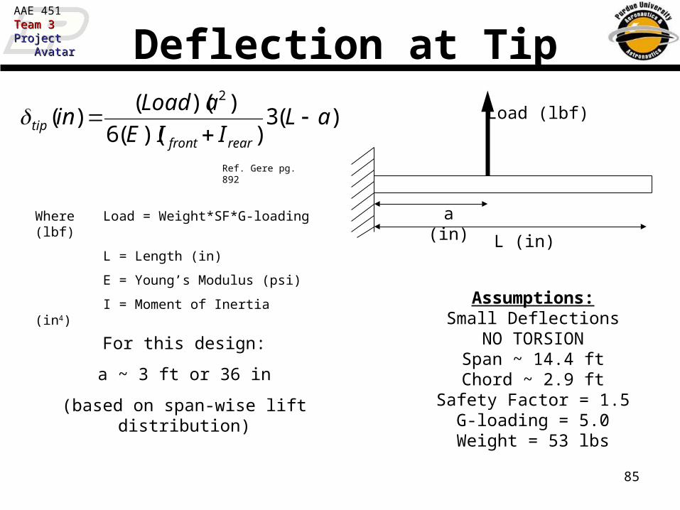
AAE 451Team 3Team 3ProjectProject AvatarAvatar Deflection at Tip
)(3))((6
))(()(
2
aLIIE
aLoadin
rearfronttip
Where Load = Weight*SF*G-loading (lbf)
L = Length (in)
E = Young’s Modulus (psi)
I = Moment of Inertia (in4)Assumptions:
Small DeflectionsNO TORSIONSpan ~ 14.4 ftChord ~ 2.9 ft
Safety Factor = 1.5G-loading = 5.0Weight = 53 lbs
Ref. Gere pg. 892
a (in)
L (in)
Load (lbf)
For this design:
a ~ 3 ft or 36 in
(based on span-wise lift distribution)

86
AAE 451Team 3Team 3ProjectProject AvatarAvatar Deflection at Tip
Chosen Spar Configuration
87
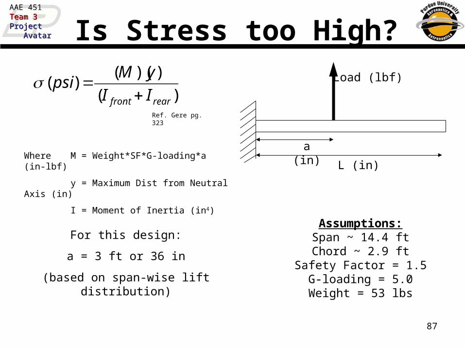
AAE 451Team 3Team 3ProjectProject AvatarAvatar Is Stress too High?
)(
))(()(
rearfront II
yMpsi
Where M = Weight*SF*G-loading*a (in-lbf)
y = Maximum Dist from Neutral Axis (in)
I = Moment of Inertia (in4)
Assumptions:Span ~ 14.4 ftChord ~ 2.9 ft
Safety Factor = 1.5G-loading = 5.0Weight = 53 lbs
Ref. Gere pg. 323
a (in)
L (in)
Load (lbf)
For this design:
a = 3 ft or 36 in
(based on span-wise lift distribution)
88
AAE 451Team 3Team 3ProjectProject AvatarAvatar Max Tension Stress

89
AAE 451Team 3Team 3ProjectProject AvatarAvatar Max Compression Stress

90
AAE 451Team 3Team 3ProjectProject AvatarAvatar Covering
• Traditional Monocote may not be strong enough for these large aircraft
• Coverite 21st Century Iron on Fabric is stronger, and resists tears much better– 0.34 oz/ft2
– Approx. 2 lbs for entire wing
Ref. www.towerhobbies.com

91
AAE 451Team 3Team 3ProjectProject AvatarAvatar
• Main Wing– Spruce or Bass wood– Front Spar
• 0.73” thick by 3.6” high
– Rear Spar• 3/8” thick by 3” high
Summary
t
h

92
AAE 451Team 3Team 3ProjectProject AvatarAvatar Rear View of Tail
Downward force from H-stab creates bending moment on beams
Side force from V-stab creates torsion effect on beams
•NOTES
•Torsion can effectively be reduced with appropriate beam spacing
•Bending can be reduced by increasing moment of inertia of beams (not spacing)
•Some torsion is inherent, torsion can not be negated as it could in wing

93
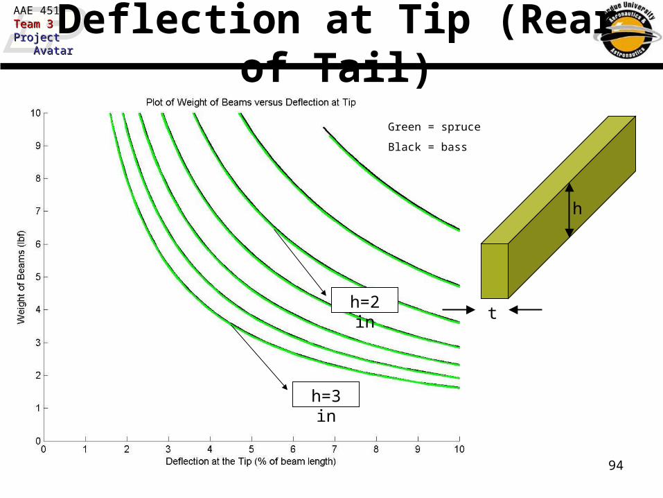
AAE 451Team 3Team 3ProjectProject AvatarAvatar Deflection at Tip (Rear of Tail)
))((3
))(.)(.)(()(
3
leftrighttip IIE
LGloadingFSLoadin
Where Load = (lbf)
L = Length (in)
E = Young’s Modulus (psi)
I = Moment of Inertia (in4)
Assumptions:Small Deflections
Safety Factor = 1.5G-loading = 3.0
Rectangular Beams
Current Known Values:L = 6.2 ft
Load ~ 8 lbf
Ref. Gere pg. 892
L (in)
Load (lbf)
Moment of inertia of rectangular beam:
I (in4) = (t)(h3)/12
t and h shown on next slide
94
AAE 451Team 3Team 3ProjectProject AvatarAvatar Deflection at Tip (Rear of Tail)
h=3 in
h=2 int
h
Green = spruce
Black = bass

95
AAE 451Team 3Team 3ProjectProject AvatarAvatar Deflection at Tip (Rear of Tail)
h=3 in
h=2 in
t
h
Green = spruce
Black = bass
Required t ~0.55 in

96
AAE 451Team 3Team 3ProjectProject AvatarAvatar Landing Gear Placement (I)
Landing gear placement based on
guidelines found in Raymer
θ = tipback angle =

97
AAE 451Team 3Team 3ProjectProject AvatarAvatar Landing Gear Placement (II)
Landing gear placement based on
guidelines found in Raymer
γ = overturn angle =

98
AAE 451Team 3Team 3ProjectProject AvatarAvatar Easily Obtainable Square Tubing
Aluminum Alloy 6061
Width (in) Height (in) Thickness (in) X-Section Area P/N 1 foot 3 feet 6 feet1 1 0.125 0.5 6546K21 $6.23 $12.43 $22.33
1 1/2 1 1/2 0.125 0.75 6546K22 $9.00 $20.75 $39.00
2 2 0.125 1 6546K23 $10.50 $25.25 $48.00
Aluminum Alloy 6063
Width (in) Height (in) Thickness (in) X-Section Area P/N 1 foot 3 feet 6 feet3/4 3/4 0.125 0.375 88875K52 $2.11 $6.34 $11.091 1 0.062 0.248 88875K51 $1.57 $4.74 $11.091 1 0.125 0.5 88875K54 $3.35 $10.00 $23.39
1 1/4 1 1/4 0.125 0.625 88875K58 $3.83 $11.49 $26.771 1/2 1 1/2 0.125 0.75 88875K61 $4.10 $12.28 $28.631 3/4 1 3/4 0.125 0.875 88875K64 $4.68 $13.97 $32.59
2 2 0.125 1 88875K67 $6.03 $18.05 $42.14
Ref. www.mcmaster.com

99
AAE 451Team 3Team 3ProjectProject AvatarAvatar
Where L = Length (in)
E = Young’s Modulus (psi)
I = Moment of Inertia (in4)
A = Cross Sectional Area (in2)
Buckling of Rear Gear
2
2
)(L
EIlbP fcr
Assumptions:
Pinned-Pinned Column1st Mode Buckling
No Eccentricity
Ref. Gere pg. 763
For Rear Gear:
L ~ 15.3 in
Load
Load
LA
Ppsi cr
cr )(

100
AAE 451Team 3Team 3ProjectProject AvatarAvatar
Where Load = (Weight)(S.F.)(Gloading)
A = Cross Sectional Area (in2)
Compressive Failure of Rear Gear
A
Loadpsic )(
Assumptions:
Weight = 53 lbfGloading = 10
S.F. = 1.5Aluminum 6061-T6
No Buckling
Load
Load
L000,34)( psicy Ref. MIL-HDBK-5H: 3-255

101
AAE 451Team 3Team 3ProjectProject AvatarAvatar Stress on Rear Gear
t=0.062”t=0.125”
Smallest easily obtainable tubing: 1” x 1” x 0.062”

102
AAE 451Team 3Team 3ProjectProject AvatarAvatar Great, what about the bungee?
• Consider worst reasonable landing situation– Moving at (1.1)Vstall
– 5 feet above ground– Aircraft falls out of the sky
• Can the bungee absorb the energy associated with this landing?

103
AAE 451Team 3Team 3ProjectProject AvatarAvatar Great, what about the bungee?
2
2
1kxW Energybungee
PEKEEtotal
2
2
1mVKE
))()(( altitudegmPE
)()( xklbF f
•Don’t want x to exceed 3 inches (beyond initial stretch) on landing
Assumptions:
Weight = 53 lbfVstall = 30 ft/secAltitude = 5 ft

104
AAE 451Team 3Team 3ProjectProject AvatarAvatar What Spring Constant is Needed?
Required k ~ 3.75 lbf/in
1/k ~ 0.266 in/lbf

105
AAE 451Team 3Team 3ProjectProject AvatarAvatar What is the Spring Constant?
Inverse of Spring Constant versus Relaxed Length
y = 0.0152x
0
0.05
0.1
0.15
0.2
0.25
0.3
0.35
0.4
0.45
0.5
0 2 4 6 8 10 12 14 16 18 20 22 24 26 28 30 32
Relaxed Length (in)
1/(S
pri
ng
Co
nst
ant)
(in
/lb
f)
Relaxed Length ~18 inches

106
AAE 451Team 3Team 3ProjectProject AvatarAvatar
If load = (Weight)(S.F.)(Gloading) = 795 lbf
Reaction = 1770 lbf (instantaneous)
Need cross sectional area of bolt to be 0.197 in2
Diameter of nylon bolt = 0.5 in
How Big is the Bolt?
0moments
)Load)(6.9"()(3.1"(Reaction)
6.9”3.1”
Load
Reaction
000,9)( psinylonult
Assumptions:
Weight = 53 lbfGloading = 10
S.F. = 1.5
Ref. Gere pg 900

PERFORMANCE

108
AAE 451Team 3Team 3ProjectProject AvatarAvatar Endurance
• Endurance = Fuel / Consumptionfuel
• Avg. Engine Fuel Consumption = 45.455 mL/min
• Endurance = 30 min

109
AAE 451Team 3Team 3ProjectProject AvatarAvatar Range
R550 p
C bhp
L
D ln
W i
W f
Since this is RC, assume almost instaneous cruise conditions
L/D = 19Cbhp = 1.5 lb/hr/bhp
Prop eff = .67Fuel Frac = 1.043

110
AAE 451Team 3Team 3ProjectProject AvatarAvatar Minimum Flight Velocity
qCl
WeightVelocity
*maxmin
Velocitymin= 29.95 ft/sec
Weight = 53 lbf
CLmax = 1.19
q =1.067 lbf/ft^2

111
AAE 451Team 3Team 3ProjectProject AvatarAvatar Rate of Climb
Vv= 7.5 ft/sec
D = 6.5lbf
hpengine = 3.7 hp
W = 53 lbf
V = 33 ft/sec
Prop Eff = .3
Vv
550hpengine p
W
D VW

112
AAE 451Team 3Team 3ProjectProject AvatarAvatar Maximum Velocity
30 40 50 60 70 80 90 1000
2
4
6
8
10
12
14
16
18
20
Flying Velocity [ft/s]
Thru
st/D
rag [
lbf]
Maximum Velocity
Thrust
Drag

113
AAE 451Team 3Team 3ProjectProject AvatarAvatar Climb Angle
asinV v
V
Vv = 7.5 ft/secV = 33 ft/sec