Performance Prediction of Nb 3 Sn CICC’s Mark D. Bird (NHMFL-FSU), DMR 0603042
Upload
ashley-walkerCategory
view
216download
0
Critical Current ProbeMid-Point Review
Amy EckerleAndrew Whittington
Philip Witherspoon
Team 16
NHMFLApplied Superconductivity Center 1

The ProjectModify existing cryostat probe to conserve the amount of
liquid helium, $5/liter of liquid He, used during a critical current measurement test.
2
Current Leads
Helium level
Cryostat
Voltage tap
MagnetSample
Voltage tap wire
Stainless Steel Jacket

Constraints
• Constraints– Test 6-8 samples– Budget of $4000– Constant casing diameter– Minimum length to reach center of cryostat
3

HTS Leads and supportSolutions
4
• Poor Conductor of heat• Low thermal conductivity with
high electrical conductivity• Great reduction in copper surface
area• Prevents copper leads from
entering liquid helium bath
G10 Support
HTS Lead

Number of LeadsSolutions
5
• Leads are major heat leak• Maintain 8 samples
with 6 leads
Current Leads
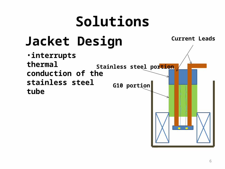
Jacket Design
Solutions
6
Current Leads
Stainless steel portion
G10 portion
•interrupts thermal conduction of the stainless steel tube
Problems
• Re-design was needed for HTS leads protection
• Previous design of sample holder was impractical– New design was made
• Ordering Problems
7
HTS Section
• High Temperature Superconducting– Eight tapes will be stacked– Reduce surface area
• Most important section• Fragile
Copper Lead HTS Lead8
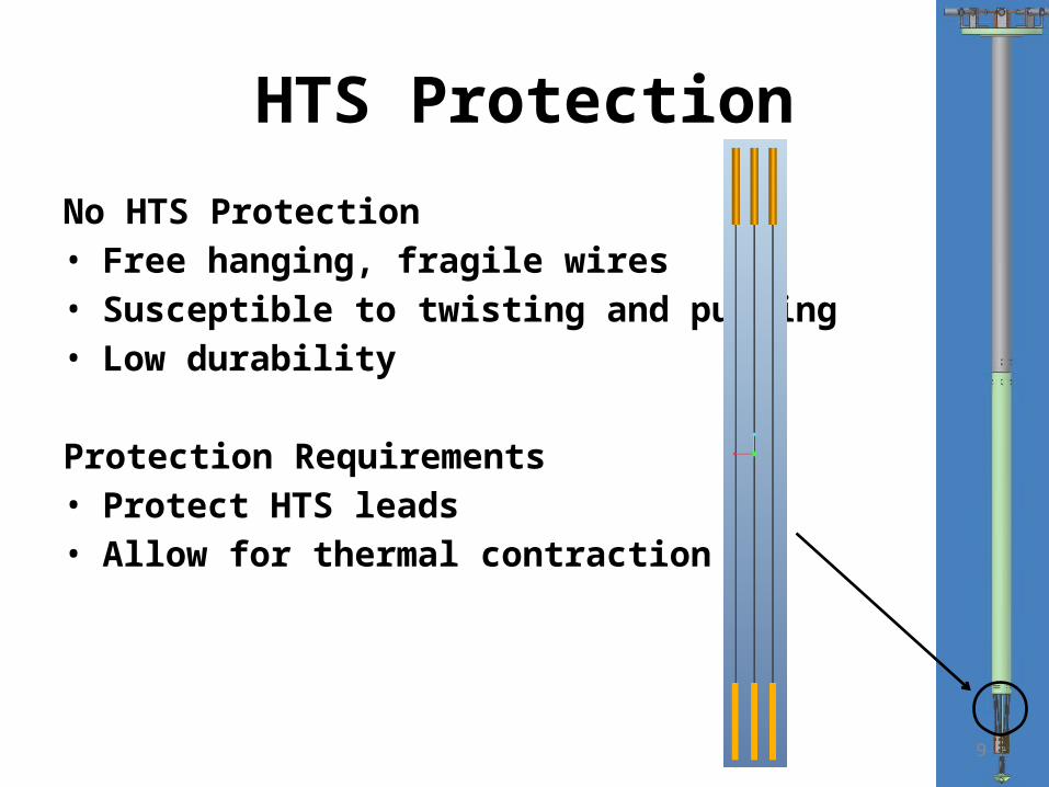
HTS Protection
No HTS Protection• Free hanging, fragile wires• Susceptible to twisting and pulling• Low durability
Protection Requirements• Protect HTS leads • Allow for thermal contraction
9

HTS Protection
Spacers• Keeps rods from swinging or touching• Have holes drilled for voltage taps,
copper leads, and support rods• Will connect to G-10 casing via holes
screws
10

HTS Protection
G-10 Support Rods• Prevents rods from twisting • Screwed into top spacer• Clamp placed on bottom spacer will
allow for upward motion
11

HTS Protection
G-10 Casing• Adds durability• Prevents bending
12
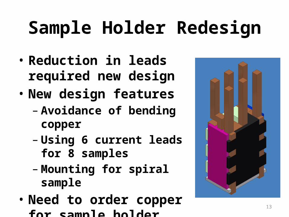
Sample Holder Redesign
• Reduction in leads required new design
• New design features– Avoidance of bending copper– Using 6 current leads for 8
samples– Mounting for spiral sample
• Need to order copper for sample holder
13
Parts en Route
• 8 ft current leads (qty. 6)• Current connects (qty. 6) • Copper for sample holder• G-10 Rods (qty. 4)• Stycast
14

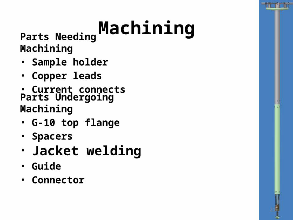
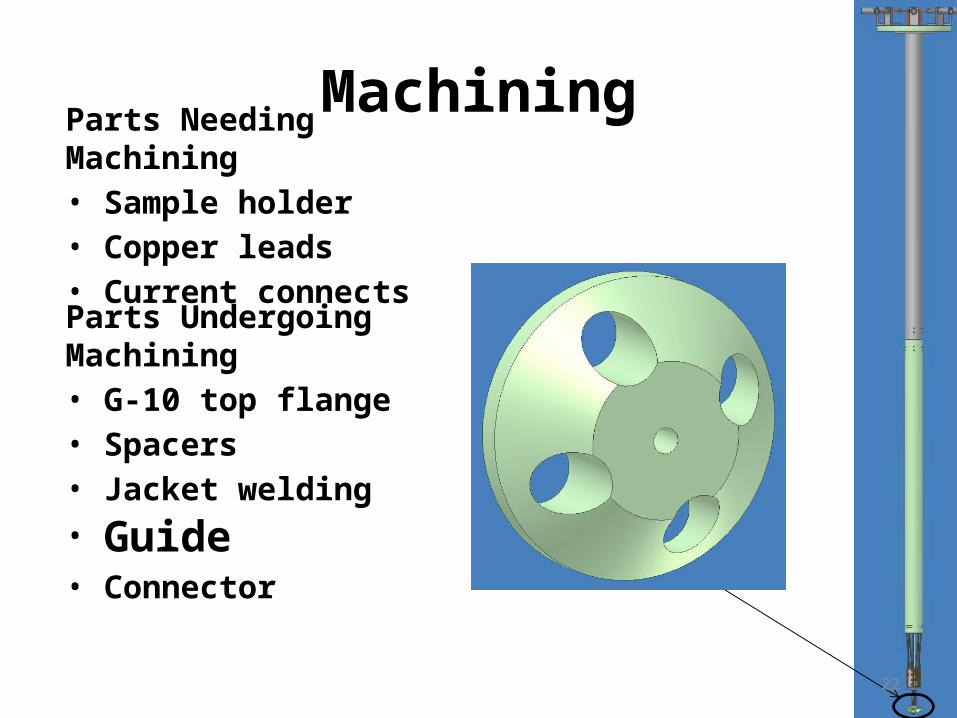
MachiningParts Needing Machining• Sample holder• Copper leads• Current connects
Parts Undergoing Machining• G-10 top flange• Spacers• Jacket welding• Guide• Connector
15

MachiningParts Needing Machining• Sample holder• Copper leads• Current connects
Parts Undergoing Machining• G-10 top flange• Spacers• Jacket welding• Guide• Connector
16

MachiningParts Needing Machining• Sample holder• Copper leads• Current connects
Parts Undergoing Machining• G-10 top flange• Spacers• Jacket welding• Guide• Connector
17

MachiningParts Needing Machining• Sample holder• Copper leads• Current connects
Parts Undergoing Machining• G-10 top flange• Spacers• Jacket welding• Guide• Connector
18

MachiningParts Needing Machining• Sample holder• Copper leads• Current connects
Parts Undergoing Machining• G-10 top flange• Spacers• Jacket welding• Guide• Connector
19

MachiningParts Needing Machining• Sample holder• Copper leads• Current connects
Parts Undergoing Machining• G-10 top flange• Spacers• Jacket welding• Guide• Connector
20
MachiningParts Needing Machining• Sample holder• Copper leads• Current connects
Parts Undergoing Machining• G-10 top flange• Spacers• Jacket welding• Guide• Connector
21
MachiningParts Needing Machining• Sample holder• Copper leads• Current connects
Parts Undergoing Machining• G-10 top flange• Spacers• Jacket welding• Guide• Connector
22

MachiningParts Needing Machining• Sample holder• Copper leads• Current connects
Parts Undergoing Machining• G-10 top flange• Spacers• Jacket welding• Guide• Connector
23

Testing
• Testing can only occur when the final design has been completely finished
• Place probe in existing cryostat for regular testing
• Compare helium losses with the existing design
• Comparing weight
24

25

Questions?
26