Criteria for Design of Pavement Thicknesses, Kentucky ...
12
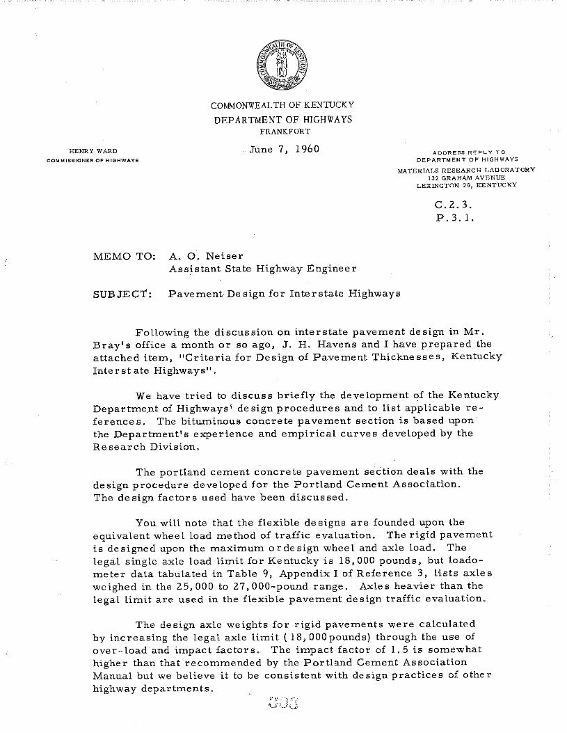
HENRY WARD COMMISSIONER OF HIGHWAYS COMMONWEALTH OF KENTUCKY DEPARTMENT OF HIGHWAYS FRANKFORT June 7, 1960 MEMO TO: A. 0. Neiser Assistant State Highway Engineer ADDRESS REPLY TO DEPARTMENT OF HIGHWAYS MATERIALS RESEARCH LABORATORY 132 GRAHAM AVENUE LEXINGTON 29, KENTUCKY c. 2. 3. P. 3. l. SUBJECT: Pavement De sign for Interstate Highways Following the discussion on interstate pavement design in Mr. Bray's office a month or so ago, J. H. Havens and I have prepared the attached item, "Criteria for Design of Pavement Thicknesses, Kentucky Interstate Highways". We have tried to discuss briefly the development of the Kentucky Department of Highways' design procedures and to list applicable re- ferences. The bituminous concrete pavement section is based upon the Department's experience and empirical curves developed by the Research Division. The portland cement concrete pavement section deals with the design procedure developed for the Portland Cement Association. The design factors used have been discussed. You will note that the flexible de signs are founded upon the equivalent wheel load method of traffic evaluation. The rigid pavement is designed upon the maximum or design wheel and axle load. The legal single axle load limit for Kentucky is 18,000 pounds, but toado- meter data tabulated in Table 9, Appendix I of Reference 3, lists axles weighed in the 25,000 to 27,000-pound range. Axles heavier than the legal limit are used in the flexible pavement design traffic evaluation. The design axle weights for rigid pavements were calculated by increasing the legal axle limit ( 18, OOOpounds) through the use of over-load and impact factors. The impact factor of 1. 5 is somewhat higher than that recommended by the Portland Cement Association Manual but we believe it to be consistent with design practices of other highway departments.
Transcript of Criteria for Design of Pavement Thicknesses, Kentucky ...
HENRY WARD
COMMISSIONER OF HIGHWAYS
COMMONWEALTH OF KENTUCKY
DEPARTMENT OF HIGHWAYS FRANKFORT
June 7, 1960
MEMO TO: A. 0. Neiser Assistant State Highway Engineer
ADDRESS REPLY TO
DEPARTMENT OF HIGHWAYS
MATERIALS RESEARCH LABORATORY 132 GRAHAM AVENUE
LEXINGTON 29, KENTUCKY
c. 2. 3. P. 3. l.
SUBJECT: Pavement De sign for Interstate Highways
Following the discussion on interstate pavement design in Mr.
Bray's office a month or so ago, J. H. Havens and I have prepared the
attached item, "Criteria for Design of Pavement Thicknesses, Kentucky
Interstate Highways".
We have tried to discuss briefly the development of the Kentucky
Department of Highways' design procedures and to list applicable re
ferences. The bituminous concrete pavement section is based upon
the Department's experience and empirical curves developed by the
Research Division.
The portland cement concrete pavement section deals with the
design procedure developed for the Portland Cement Association.
The design factors used have been discussed.
You will note that the flexible de signs are founded upon the
equivalent wheel load method of traffic evaluation. The rigid pavement
is designed upon the maximum or design wheel and axle load. The
legal single axle load limit for Kentucky is 18,000 pounds, but toado
meter data tabulated in Table 9, Appendix I of Reference 3, lists axles
weighed in the 25,000 to 27,000-pound range. Axles heavier than the
legal limit are used in the flexible pavement design traffic evaluation.
The design axle weights for rigid pavements were calculated
by increasing the legal axle limit ( 18, OOOpounds) through the use of
over-load and impact factors. The impact factor of 1. 5 is somewhat
higher than that recommended by the Portland Cement Association
Manual but we believe it to be consistent with design practices of other
highway departments.
A. 0. Neiser ~ 2 - June 7, 1960
We have prepared a section listed as "Equivalency of Design"
that we think should be helpful in equating traffic evaluation and pave
ment design. Please advise if there are any other items that you
would recommend for consideration.
WBD:dl
Encs.
~ W. B. Drake
Associate Director of Research

CRITERIA FOR DESIGN OF PAVEMENT THICKNESSES
KENTUCKY INTERSTATE HIGHWAYS
Bituminous Concrete Pavements
The Kentucky Department of Highways, in 1946, sought a more
systematic criteria and basis for designing the thickness of bituminous
concrete pavements. The Research Division was authorized to pursue
this work and to develop the criterion. These efforts were embodied
in a report (1) to the Department, which offered a system of de sign
based upon CBR 's and EWL's. EWL's were computed originally for a
10-yr. period but this practice was revised in 1954, to encompass 20-yr.
traffic (more realistic with respect to average road life). Then, in 1957,
the Department requested a re-evaluation of the criteria from the stand-
point of experience and performance of pavements designed thereby.
This re-study and recommendations was reported to the Department
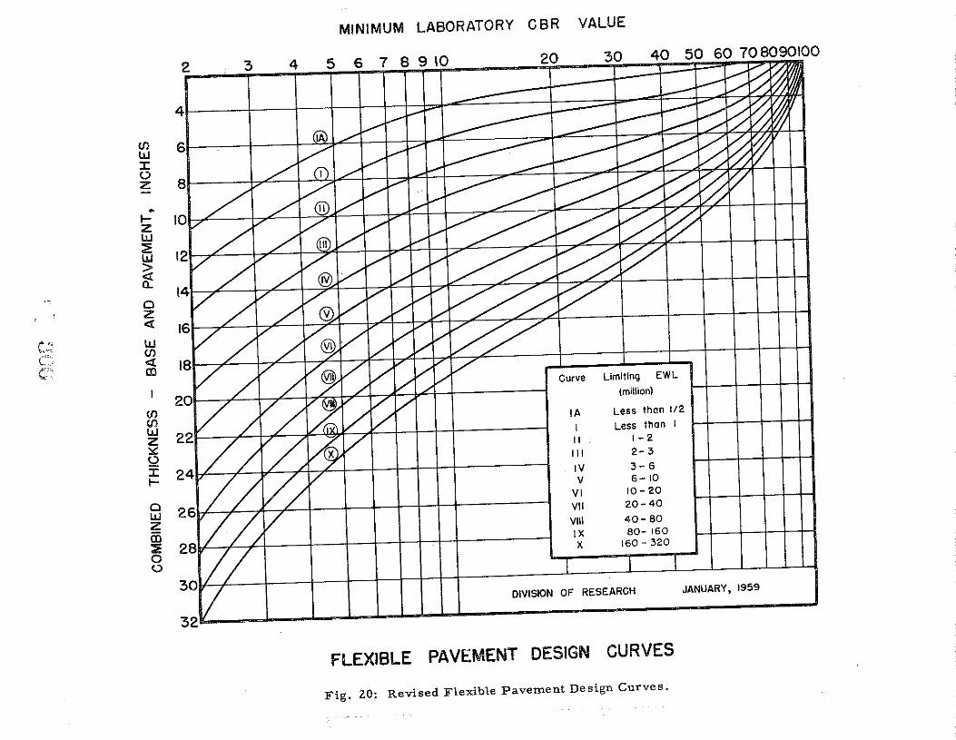
and to the Highway Research Board (2)(3). A copy of current de sign
chart is shown on the following page (Fig. 20, ref. 2 and 3).
( 1) Baker, R. F. and Drake, W. B., "lnves tigation of Field and Labora
tory Methods for Evaluating Sub grade Support in the De sign of High
way Flexible Pavements, 11 Bulletin No. 13, Engineering Experimental
Station, University of Kentucky, Sept. 1949.
(2) Drake, W. B. and Havens, J. H., "Re-EvaluationofKentucky
Flexible Pavement Design Criterion," Bulletin No. 233, Highway
Research Board, 1959.
(3) Drake, W. B. and Havens, J. H., "Kentucky Flexible Pavement De
sign Studies," Bulletin_No. 52, Engineering Experiment Station,
University of Kentucky, 1959.
- 1 -
(/) w :I: (,) z
p
~ z w ::2: w > ~ 0 z <l , .. w
,-'-~ (/) C; <l cr· CD
I
(/) (/) w z ::.:: (,)
:X: ~
0 w z CD ::2: 0 (,)
MINIMUM LABORATORY CBR VALUE
2 3 4 7 8 9 10 30 40 50 60 70 8090100
6~~~--~~~~-4-+~~~--~~+-~--~~~~
~~~~
8~----~~4-~~~-r~~4---~--=--r~~~~
~~~~~r-
10~~--~~4-~~~-t~~4-~~~~~~~7¥~~
~~~
20 :>
~~ :~~A ~~illY~~ ::~~~~ MVAA~~ ~:vx~ ?J/A/~ ?d'/ /VA' 2~V/X ~J// ::v
Curve
I
lA
I II Ill
IV v
VI VII
VIII IX X
Limiting EWL
(million)
Less than 112
Less than I I I I I I I I 1-2
2-3
3-6 6-10
10-20
20-40
40-80 80- 160
160- 320
I
DIVISION OF RESEARCH JANUARY, 1959
FLEXIBLE PAVEMENT DESIGN CURVES
Fig. ZO: Revised Flexible Pavement Design Curves.
- 3 -
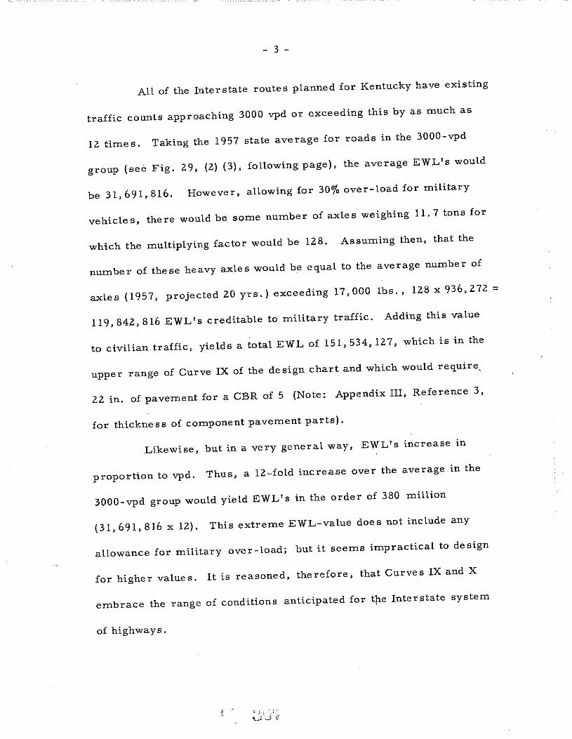
All of the Interstate routes planned for Kentucky have existing
traffic counts approaching 3000 vpd or exceeding this by as much as
12 times. Taking the 1957 state average for roads in the 3000-vpd
group (see Fig. 29, {2) (3), following page), the average EWL's would
be 31,691,816. However, allowing for 30o/o over-load for military
vehicles, there would be some number of axles weighing 11.7 tons for
which the multiplying factor would be 128. Assuming then, that the
number of these heavy axles would be equal to the average number of
axles (1957, projected 20 yrs.) exceeding 17,000 lbs., 128 x 936,272 =
119,842,816 EWL's creditable to military traffic. Adding this value
to civilian traffic, yields a total EWL of 151,534,127, which is in the
upper range of Curve IX of the de sign chart and which would require ..
22 in. of pavement for a CBR of 5 (Note: Appendix III, Reference 3,
for thickness of component pavement parts).
Likewise, but in a very general way, EWL's increase in
proportion to vpd. Thus, a 12~fold increase over the average in the
3000-vpd group would yield EWL' s in the order of 380 million
(31, 691,816 x 12). This extreme EWL-value does not include any
allowance for military over-load; but it seems impractical to design
for higher values. It is reasoned, therefore, that Curves IX and X
embrace the range of conditions anticipated for t[le Interstate system
of highways.
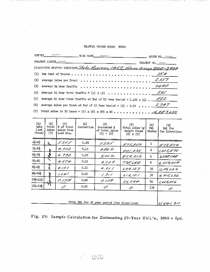
TR>\.l'FIC 1!0LUNE: GROUP 3000+
CO~~~---------------RO,W NM~'---=====------------------ ROUTE NO,_;;==--
PROJECT LIMITS...:·==------------------------------------ PROJECT NO,....::· ==-----LO~DOI('!T8R STATIO'' REFERE~!CE5/q/,-, h".ve"...-"'90:: /9._5-z·hfdeze; LP<<Z«rt? .jCCJc7-.::f9.29 (1) Per Cent of Trucks • • •
(2) Average Axles per Truck
(3) Average 24 Hour Traffic
(4) Average 24 Hour Tr'tclc Traffic = (1) x (3)
(5) Average 24 Hour Truck Traffic at End of 10 Year Period = 1.465 x (4)
(6) Aver~ge Axles per Truck at End of 10 Year Period = (2) + 0.19
(7) Total Axles in 20 Years = (5) x (6) x 365 x 20 , • , , . .
(A) (B) (C) (D) (E) (F) Axle Total % of Total Correction Corrected % Total Arl.es by road Axles Axles From of Total Axles Weight Class
(Tons) (7) Load Sta. (G) + (D) (B) X (E)
4i-5t ~ J'ZO~ 0.09 S.Z9.:>"' 5'7Z.8C9 5t-6! ~ ?-, ?3Z:. 0,13 ~5'6 z- 5'?7/ ?-35 6-~-?t ~ ?-. 73Z 0,27 6: ,?'cJ z... ,!? z ..; .:5' / z. 7t-st ' "".:5'7"" 0,15 "f', ?Z ,1- '7?,5J' 65'8' 8t-9l ~ .,£;/0/ 0.11 .;', Z/ / 6tJ.;!. /Z 7 9]-..lot ~ /.Z-6/ 0,05 /. 3// Z./ t6 /Cl /
10!-Ilt ~ c?, /35 0,00 C./38 .?«;cJ<f',? lli-12]- 'l 0 0,00 c? c?
TOTAL El.JL for 20 year period ~two directions~
/5.4-.Z.5.57
56/
(G) (H) EWL EWL for
Factor Two Directions
1 87;;;5'c9 2 t. bc?~#7CJ 4 .$.Z~<74-c?
8 if ZZ!f?$C1-?-
16 /? /?lo! CJ3 z..
32 ~ $7/.:>;" ..?3?
64 ,; ""'~,P/6
128 c?
3/60/ 3/1
Fig. 29: Sample Calculation for Estimating 20-Year EYIL's, 3000 + .Jpd.

- 5 -
Portland Cement Concrete Pavements
Thickness designs for portland cement concrete pavements in
Kentucky have been based largely upon the stylized cl'i.terion offered
by the Portland Cement Association (4) which, of course, is founded
on the work of well-known scholars. It is reasoned, however, that the
suggested methods therein of determining the "controlling wheel load"
and "de sign life" may be arbitrary and argumentive. In the applicable
equation (protected corners, Formula 1), P, the design wheel load,
is the design static wheel load multiplied by a judicious impact factor
(see following discussion). If Pis taken as the legal. load limit (9-ton
axle, 4.5 ton wheel toad), "design life" would simply be the number of
years to accumulate 100,000 or more repetitions of the legal wheel
toad. Under other circumstances the prevailing 100,000 heaviest wheel
toads (loadometer data) might be used for design even though such a
value might exceed the legal toad limit. Similarly, the legal wheel-toad
limit might be used as a basis but with due allowances for a percentage
and frequency of over-loads. Either approach should anticipate future
increases in axle loads and the eventual increase in the axle toads per-
mit ted by Kentucky weight taws.
It is proposed for the design of Interstate roads: (1) that the
present legal axle toad limit, 18,000 tbs., be used as the basic axle
toad, (2) that a 30o/o over-toad allowance for military and civilian traffic
be used (18,000 x 130o/o = 23,400 lb. axle or 11,700-lb. wheel), and (3)
that an hnpact factor of 1. 5 be used instead of 1. 2, the more common
(4) Concrete Pavement Design ... , PCA, 1951.
',., .. _
· .• :',..,~1.1
- 6 -
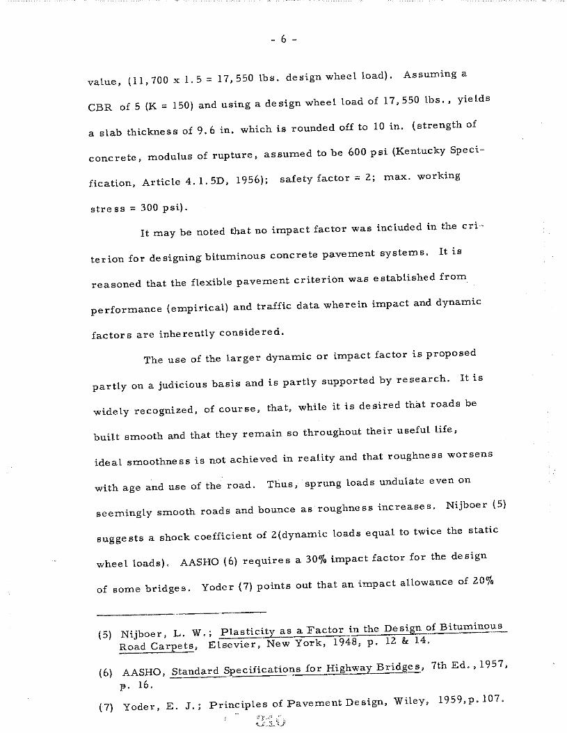
value, (11, 700 x l. 5 = 17,550 lbs. design wheel load). Assuming a
CBR of 5 (K = 150) and using a de sign wheel load of 17, 550 lbs. , yields
a slab thickness of 9. 6 in. which is rounded off to 10 in. (strength of
concrete, modulus of rupture, assumed to be 600 psi (Kentucky Speci-
fication, Article 4.l.5D, 1956); safety factor= 2; max. working
stress = 300 psi).
It may be noted that no impact factor was included in the cri-
terion for designing bituminous concrete pavement systems. It is
reasoned that the flexible pavement criterion was established from
performance (empirical) and traffic data wherein impact and dynamic
factors are inherently considered.
The use of the larger dynamic or impact factor is proposed
partly on a judicious basis and is partly supported by research. It is
widely recognized, of course, that, while it is desired that roads be
built smooth and that they remain so throughout their useful life,
ideal smoothness is not achieved in reality and that roughness worsens
with age and use of the road. Thus, sprung loads undulate even on
seemingly smooth roads and bounce as roughness increases. Nijboer (5)
suggests a shock coefficient of Z(dynamic loads equal to twice the static
wheel loads). AASHO (6) requires a 30o/o impact factor for the design
of some bridges. Yoder (7) points out that an impact allowance of 20%
(5) Nijboer, L. W.; Plasticity as a Factor in the Design of Bitumino':l...':_
Road Carpets, Elsevier, New York, 1948, p. 12 & 14.
(6) AASHO, Standard Specifications for Highway Bridges, 7th Ed., 1957,
]3 0 16 0
(7) Yoder, E. J.; Principles of Pavement Design, Wiley, 1959,p.107.

~ 7 -
(1. 2) is commonly used, but he also refers to BPR tests which indicate
impact due to a load passing over an obstruction to be 150o/o greater than
the static load.
It is apparent from other studies that moving wheel loads
may at times be less than static loads and at other times considerably
higher than the static load, In fact, it appears that our present knowledge
of this factor is rather inconclusive and that further research is needed
in regard to this important aspect of pavement design. Several related
additional references are offered in support of this contention, (8, 9, 10,
11 & 12).
In any case, the use of over~load factors and dynamic factors
to project the pre sent legal axle load is an expedient estimate of future
trends in highway transportation. The assumption of 30% over-load
( 18,000 x I. 3 = 23, 400) may, in fact, be a conservative estimate of
future trends in axle loads. In Maryland ( 13), for instance, the
(8) Bonse, R.P.H. and Kuhn, S. H.; "Dynamic Forces Exerted by Movirig Vehicles on a Road Surface", Bulletin No. 233, HRB, 1959.
(9) Biggs, J.M., Suer, H.S., and Louw, J.M.; "Progress Report No. 2, Bridge Vibrations", Research Report No. 19, Joint Highway Research Project, MIT, July 1956.
(10) Gesund, Hans; "The Dynamic Response of Beams to Moving Mass Loads," Ph. D. Dissertation, Yale School of Engineering, 1958.
(11) Norman, 0. K. and Hopkins, R. C.; "Weighing Vehicles in Motion", Public Roads, April, 1952.
(12) Hopkins, R.C. and Boswell, H.H.; "A Comparison of Methods Used for Measuring Variations in Loads Transferred Through Vehicle Tires to the Road S.urface, Public Roads, Oct. 1957.
( 13) Lee, Allen; "Experience with Flexible Pavements in Maryland", Bulletin No. 136, HRB, 1956 .
._f"A:• ',
IL:1J •. L _::;~

- 8 -
prevailing legal axle load limit is 22,400 lbs., plus .!Oo/o impact factor,
and special registration of dump trucks operating within a 40-mi. radius
permits axles loads of 28,000 and 31,000 lbs.
This criterion further proposes the use of 6 in. of granular
insulation or base under concrete pavement slabs. This practice anti-
cipates an extreme depth of frost penetration of 18 in. or less and that
a mini mum of 4 in. base is needed to safe- guard against pumping. The
preferred 6-in. base is in line with common practices elsewhere and
with recent studies ( 14)(15) related thereto.
(14) Childs, L. D. and Kapernick, J. W.; "Test of Concrete Pavements on Gravel Sub-bases", Journal of the Highways Division, Proceedings, ASCE, Paper 1800, Vol. 84, October, 1958.
(.!5) Colley, B. E.,: and Nowlen, J. W.; "Performance of Subbases for Concrete Pavements under Repetitive Loading", Bulletin No. 202, HRB, 1958,

- 9 -
Equivalency of De sign~
Although equivalency in design may be inferred from the fore-
going criteria, mathematical substantiation is lacking. Fergus (2)(3)
derived a formula relating EWL's to equivalent single axle load (basis
for concrete pavement design). A slightly modified derivation is offered
below as a matter of interest:
I. Axle loads, in tons (P) increase arithmetically:
L = a+ (n - I) d
a = 1st term = 5 tons (basic)
n = no. of terms
d = common difference = I
.L = last term = P
P = 5 + (n - 1) 1
P-5=n-l
2. Both EWL' s and California Factors increase geometrically:
.L = a r n-1
L = last term n-1
L = a(2)
a = 1st term = k (basic); n - 1 = P - 5
r = common ratio = 2
thus:
EWL's = k(2) P-5
and:
f = k'(2)P- 5 , k' = 1 (basic)
3. Since:
EWL = n f =;En 1£1 + n 2£2 ...
EWL (millions) =n (2) P_::S

- 10 -
Therefore, if it is assumed that 256 million EWL's (mid-value
of Curve X) is equivalent to a 24,000-lb. axle load (18,000 legal axle
x 1.3 over-load= 23,400 lbs. (static) or 35, 100-lbs. (dynamic), basis
for portland cement concrete pavement de sign), then:
256 x 106 = n. (2)12
-5
- 6 and n = 2 x 10
It follows, then, that all other axles and EWL's may be equated
similarly (2 million EWL's = 10,000 axle load) and that equivalent
design thicknesses may be interpolated from the respective design
charts. Although a true basis for adjudging equivalency in designs has
been and is desired, it must be recognized that the above derivation is I
based upon an assumed equivalency, i.e. 256 million EWL' s = 24, 000
lb. static axle or a 35, 100-lb. dynamic axle.