Creo Elements/Direct Modeling Annotation Manual - …...Creo Elements/Direct Modeling Annotation...
112
Creo Elements/Direct Modeling Annotation Manual March, 2016 Creo Elements/Direct Modeling Annotation Manual Version 1.0
Transcript of Creo Elements/Direct Modeling Annotation Manual - …...Creo Elements/Direct Modeling Annotation...

Creo Elements/Direct Modeling Annotation Manual
March, 2016
Creo Elements/Direct Modeling Annotation Manual
Version 1.0

Creo Elements/Direct Modeling Annotation Manual
March, 2016 i
Copyright March, 2016 by Owens-Illinois Global Technology and Operations.
All Rights Reserved
Printed in USA
The information contained herein constitutes proprietary confidential and trade
secret information of Owens-Illinois Global Technology and Operations, and is to
be accepted subject to that understanding. It is to be kept confidential and not be
copied, used, or conveyed to others without Owens-Illinois Global Technology and
Operations' written authorization.
The information contained in this technical manual is offered in good faith by
Owens-Illinois Global Technology and Operations, however, Owens-Illinois Global
Technology and Operations MAKES NO REPRESENTATION OR WARRANTY
OF ANY TYPE, EXPRESS OR IMPLIED, REGARDING ANY PROCEDURES,
OR ANY OTHER INFORMATION SET FORTH IN THIS REPORT, AND THE
CUSTOMER ASSUMES ALL RESPONSIBILITY FOR THE ADEQUACEY,
FITNESS, AND ACCURACY OF ANY PROCEDURES, SUGGESTIONS, OR
INFORMATION USED IN ANY MANUFACTURING, PACKAGING, OR
PROCESSING OPERATIONS, INCLUDING LOSS DUE TO PERSONAL
INJURY OR PROPERTY DAMAGE.

Creo Elements/Direct Modeling Annotation Manual
March, 2016 ii
Table of Contents 1 Navigation of Annotation commands. .................................................................................................. 1
2 Browser Bar ........................................................................................................................................... 4
3 Create a new drawing. .......................................................................................................................... 4
4 Adding a sheet to a drawing. ................................................................................................................ 7
5 Adding views. ........................................................................................................................................ 8
6 Creating Dependent Views. .................................................................................................................. 9
Section Views. ............................................................................................................................... 9
6.1.1 Direction of Section Arrows. ............................................................................................... 12
6.1.2 Aligned Sections. ................................................................................................................. 12
6.1.3 Secured Parts. ..................................................................................................................... 13
Detail Views. ............................................................................................................................... 18
Partial Views. ............................................................................................................................... 20
Partial to Full. .............................................................................................................................. 21
Cutaway Views. ........................................................................................................................... 23
Remove Cutaway. ....................................................................................................................... 26
Broken Views. ............................................................................................................................. 27
Dependent General Views. ......................................................................................................... 29
7 Updating Views. .................................................................................................................................. 30
8 Moving Views. ..................................................................................................................................... 31
Moving views between sheets. ................................................................................................... 31
9 Viewsets. ............................................................................................................................................. 32
10 Attaching a drawing to a variant. ........................................................................................................ 33
11 Attach a drawing to a copy. ................................................................................................................ 35
12 Attach a drawing to Mirror. ................................................................................................................ 35
13 View Properties. .................................................................................................................................. 37
14 Calc Modes. ......................................................................................................................................... 41
15 View Profiles. ...................................................................................................................................... 42
The view profile sets the following. ............................................................................................ 43
16 Select which parts have hidden lines and tangent lines. .................................................................... 43
17 Creating, Placing and editing texts and symbols. ............................................................................... 45

Creo Elements/Direct Modeling Annotation Manual
March, 2016 iii
Texts. ........................................................................................................................................... 45
Symbols. ...................................................................................................................................... 48
18 Ownership. .......................................................................................................................................... 50
Changing the owner of a symbol or text. .................................................................................... 51
19 Linear Dimensioning. .......................................................................................................................... 51
Single dimensions. ...................................................................................................................... 51
Tangential linear dimensioning. .................................................................................................. 52
Datum Long. ................................................................................................................................ 54
Datum Short ................................................................................................................................ 54
Chain Dimensioning. ................................................................................................................... 56
Coordinate Dimension. ............................................................................................................... 57
19.6.1 External Base Points. ........................................................................................................... 59
Chamfer ....................................................................................................................................... 62
Symmetry Single, Symmetry Long .............................................................................................. 63
Put Dim In /Take Dim Out. .......................................................................................................... 65
19.9.1 Take Dim Out Datum Long Dimensions. ............................................................................. 66
19.9.2 Put Dim In for Datum Long Dimensioning. ......................................................................... 67
19.9.3 Take Dim Out for Chain Dimensioning. ............................................................................... 68
19.9.4 Put Dim In for Chain Dimensions. ....................................................................................... 70
19.9.5 Put Dim In and Take Dim Out for Coordinate Dimensions. ................................................ 71
20 Circular Dimensioning. ........................................................................................................................ 72
Radii. ........................................................................................................................................... 72
Diameters. ................................................................................................................................... 76
Tapped Holes. ............................................................................................................................. 77
Counterbore and Countersunk holes. ......................................................................................... 78
21 Tangential............................................................................................................................................ 81
22 Arc dimensioning. ............................................................................................................................... 81
23 Angular Dimensioning. ........................................................................................................................ 83
Dimension Properties. ................................................................................................................ 85
Stagger extension Lines/move dimension text. .......................................................................... 85
Break Extension Lines. ................................................................................................................ 88

Creo Elements/Direct Modeling Annotation Manual
March, 2016 iv
24 Editing dimensions and Dim Fix Texts. ................................................................................................ 91
25 Manage Parts. ..................................................................................................................................... 91
Remove Parts. ............................................................................................................................. 92
Add Parts. .................................................................................................................................... 93
26 Using Configurations to Create Views. ............................................................................................... 94
27 Shading a view. ................................................................................................................................... 97
28 Change Part Color. ............................................................................................................................ 100
29 Improving Update Performance. ...................................................................................................... 102
Remove Invisible. ...................................................................................................................... 102
Calc Mode. ................................................................................................................................ 103
30 Appendix. .......................................................................................................................................... 105
Fixing the View Reference Points.............................................................................................. 105
31 Revision History. ............................................................................................................................... 107
32 Credits ............................................................................................................................................... 107
33 Endnotes. .......................................................................................................................................... 107

Creo Elements/Direct Modeling Annotation Manual
March, 2016 1
1 Navigation of Annotation commands. Annotation commands can be accessed in several different places. Commands are in the ribbon menu,
the Mini Toolbar, the right mouse click menus, the side bar menus and several O-I company defined
toolbars.
When a command is started, a Dialog Box will open. The Dialog Box shows all of the operations available
for a given command.
Some Dialog Boxes can be expanded to provide more options. Expand these Dialog Boxes by clicking the
double down arrow. The Dialog Boxes can be shrunk by clicking the double up arrow.
Figure 1-1 Expand the Dialog Box.
Figure 1-2 Shrink the Dialog Box.
If a command is started with the Mini Toolbar, the Dialog Box may not show. To show the Dialog Box,
click the green arrow to expand the command. To have the Dialog Box open by default when a
command is started from the Mini Toolbar, click the icon shown in FIGURE 1-3.
Figure 1-3 Display Dialog box when a command is started from a Mini Toolbar.
Figure 1-4 This is a typical Dialog Box.
Several customized commands are in the O-I toolbars. To display these toolbars go to
File Customize

Creo Elements/Direct Modeling Annotation Manual
March, 2016 2
This will open up the Customize Command window.
Select the Toolbars tab. Toolbars can be displayed by clicking the radio button next to the toolbar. Drag
the toolbars to a desired location on the borders. O-I customized toolbars have “O-I” in the name.
Figure 1-5 Customize Toolbars menu.
Figure 1-6 Example of toolbars placed on the border.

Creo Elements/Direct Modeling Annotation Manual
March, 2016 3
Toolbar name Toolbar functions
O-I Annotation Utilities
Update drawing, update view, Inch settings, metric settings, fractional settings, insert change card
O-I Basic Dimensions
Suppress the leading zero, Modify dimension decimal places to 1, 2 or 3, suppress dimension trailing zero, modify dimension turn basic box on, turn basic box off, Turn basic box on/Off for selected dimensions, add parenthesis to selected dimensions
O-I Dimension Modification
Modify dimension to metric, fractional inch, decimal inch, Modify dimension text to vertical/horizontal, break overlapping extension lines
O-I Model Manager 3D
Open Workspace, Save 2D (recommended), Save (slower), Add thumbnail, DB drawing properties, Reserve, Unreserve, Update title block, Start Model Manager, Stop Model Manager
O-I Text Modification
Change Text Ratios, 1:1, .0.8:1, 0.7:1, 0.6:1. Change text color to Orange, Blue, Bold printing Green, Yellow, Change leader to yellow, Change leader to non-printing blue.
Table 1 Suggested Annotation toolbars.
For a full explanation of the O-I Toolbars, please see the document Creo Elements/Direct Modeling O-I
Toolbar Menus.

Creo Elements/Direct Modeling Annotation Manual
March, 2016 4
2 Browser Bar The browser bar in Annotation has three different Browser Views that will be used on a regular bases.
Change the Browser View by clicking the appropriate icon on top of the Browser Bar.
Figure 2-1 Structure Browser
The Structure Browser View shows all of the models currently loaded.
Figure 2-2 Template Browser
The Template Browser shows all of the Corporate and User defined Text, Symbol, and Drawing templates.
Figure 2-3 Drawing Browser
The Drawing Browser shows the current drawing, the sheets in the drawing and what views are on each sheet.
3 Create a new drawing.
Figure 3-1 Start the New Drawing command.
Start the New Drawing command. Annotation will give a warning if a drawing is currently loaded.

Creo Elements/Direct Modeling Annotation Manual
March, 2016 5
Figure 3-2 Select the Front and Up Direction.
Select the Owner of the view. Select the Front direction by Clicking the Front Dir button and then clicking the face, an edge or a pair of points to define the front direction. The arrow will point into the view.
Figure 3-3 The arrow points into the view.
Pressing the Tab key will toggle the arrow direction.
Figure 3-4 Right click options.
The default direction selection defaults to +/- Face direction and edge tangent direction. Right clicking brings up a menu with more direction options such as direction by Two Points. Click the Up Direction and select an edge, a face or two points for the direction. Again, pressing the tab key will toggle the arrow direction.

Creo Elements/Direct Modeling Annotation Manual
March, 2016 6
Figure 3-5 Select the Sheet size.
Select the appropriate sheet size for the drawing. The Sheet size can always be changed later if more space for views is required. (The user must be logged into Model Manager to see the title blocks.)
Figure 3-6 click the Add Views button.
Click the Add Views button to expand the Create Drawing menu.
Creo Elements/Direct Modeling Annotation Manual
March, 2016 7
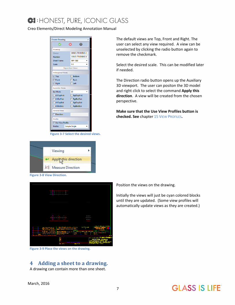
Figure 3-7 Select the desired views.
Figure 3-8 View Direction.
The default views are Top, Front and Right. The user can select any view required. A view can be unselected by clicking the radio button again to remove the checkmark. Select the desired scale. This can be modified later if needed. The Direction radio button opens up the Auxiliary 3D viewport. The user can positon the 3D model and right click to select the command Apply this direction. A view will be created from the chosen perspective. Make sure that the Use View Profiles button is checked. See chapter 15 VIEW PROFILES.
Figure 3-9 Place the views on the drawing.
Position the views on the drawing. Initially the views will just be cyan colored blocks until they are updated. (Some view profiles will automatically update views as they are created.)
4 Adding a sheet to a drawing. A drawing can contain more than one sheet.
Creo Elements/Direct Modeling Annotation Manual
March, 2016 8
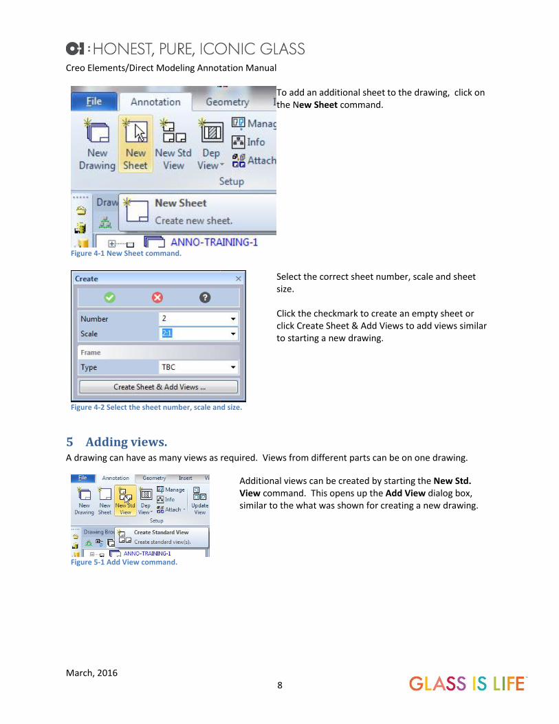
Figure 4-1 New Sheet command.
To add an additional sheet to the drawing, click on the New Sheet command.
Figure 4-2 Select the sheet number, scale and size.
Select the correct sheet number, scale and sheet size. Click the checkmark to create an empty sheet or click Create Sheet & Add Views to add views similar to starting a new drawing.
5 Adding views. A drawing can have as many views as required. Views from different parts can be on one drawing.
Figure 5-1 Add View command.
Additional views can be created by starting the New Std. View command. This opens up the Add View dialog box, similar to the what was shown for creating a new drawing.

Creo Elements/Direct Modeling Annotation Manual
March, 2016 9
Figure 5-2 Add Views Dialog Box.
Add additional views by selecting any of the Orthogonal Views, Isometric views, or General View. To add views from a different part, click Owner and select the Model, and set the Front Dir and Up Dir as when creating a new drawing.
6 Creating Dependent Views. Dependent views are views created from an existing view. These include section views, detail views,
partial views, cutaway views, broken views and dependent general views. The appearance of dependent
views can be changed by modifying the view properties. See chapter 13 VIEW PROPERTIES.
Section Views.
Figure 6-1 Start the Cross Section command.
The Create Section view command is in the Mini Toolbar and in the annotation tab under the Dep View menu. Start the Create Section View command.

Creo Elements/Direct Modeling Annotation Manual
March, 2016 10
Figure 6-2 Dep View Menu.
Figure 6-3 Select the parent view a sketch the section lines.
Select the Parent view to create the section from. Once the parent view is selected, Annotation will show temporary Auxiliary lines. These lines represent symmetry and centerlines and can be used to aid in drawing the section line. If needed for clarity, these can be turned off as shown below.
Figure 6-4 Auxiliary lines.
Uncheck the Auxiliary lines radio button to hide the Auxiliary lines.

Creo Elements/Direct Modeling Annotation Manual
March, 2016 11
Figure 6-5 Right Click and Accept the Section Line.
To add the section lines, simply sketch the lines on the view. The Section Line can have multiple segments if needed. After the lines are complete, right click and Accept the Section Line. Annotation will draw the section arrows.
Figure 6-6 Reverse or Swap the Arrow Direction if needed.
If the arrows are pointing in the wrong direction, simply click Reverse Dir. The Swap Dir button swaps the arrow directions in multi-segment sections when they arrows are not aligned.
Figure 6-7 Surface Mode: Off
Surface Mode toggles between showing the whole part at the section and showing only the surface at the section. The view shown to the left is with Surface Mode: Off

Creo Elements/Direct Modeling Annotation Manual
March, 2016 12
Figure 6-8 Surface Mode: On
The view on the left is the same as the above view with Surface Mode: On. The Surface Mode On has two options.
- On, No Secured Parts. - On, Incl. Secured Parts (see Chapter
6.1.3 SECURED PARTS)
6.1.1 Direction of Section Arrows.
The direction the section line is drawn, influences the direction the section arrows are pointing. The
arrow direction can be reversed or swapped afterwards as noted above.
Direction Lines are drawn Section Arrow Direction
Bottom to Top Arrows point to the left
Top to Bottom Arrows point to the right
Left to Right Arrows point up
Right to Left Arrows point down
6.1.2 Aligned Sections.
Section views can be created from multiple segment section lines. The radio button Aligned determines
how this view is generated.
Figure 6-9 Section view with the Aligned button unchecked.
If the Aligned radio button is unchecked, the section arrows point perpendicular to the last segment drawn.

Creo Elements/Direct Modeling Annotation Manual
March, 2016 13
Figure 6-10 Section view with the aligned button checked.
If the Aligned radio button is checked both arrows will be perpendicular to the segment that they are attached.
6.1.3 Secured Parts.
A secured part will not be sectioned. A part can be universally defined as secured (Influenced in
General). This prevents the part from being sectioned by anyone that would create a drawing with this
part. A part can also be defined as secured for just selected views.
6.1.3.1 Securing a part in general.
A part can be universally defined as secured. This will keep the part from sectioning in any view created
by that part. This can be accomplished directly on the 3D modeling without having to go through
annotation.
Figure 6-11 Start the secure part command in Modeling .
Start the Secure command.
Creo Elements/Direct Modeling Annotation Manual
March, 2016 14
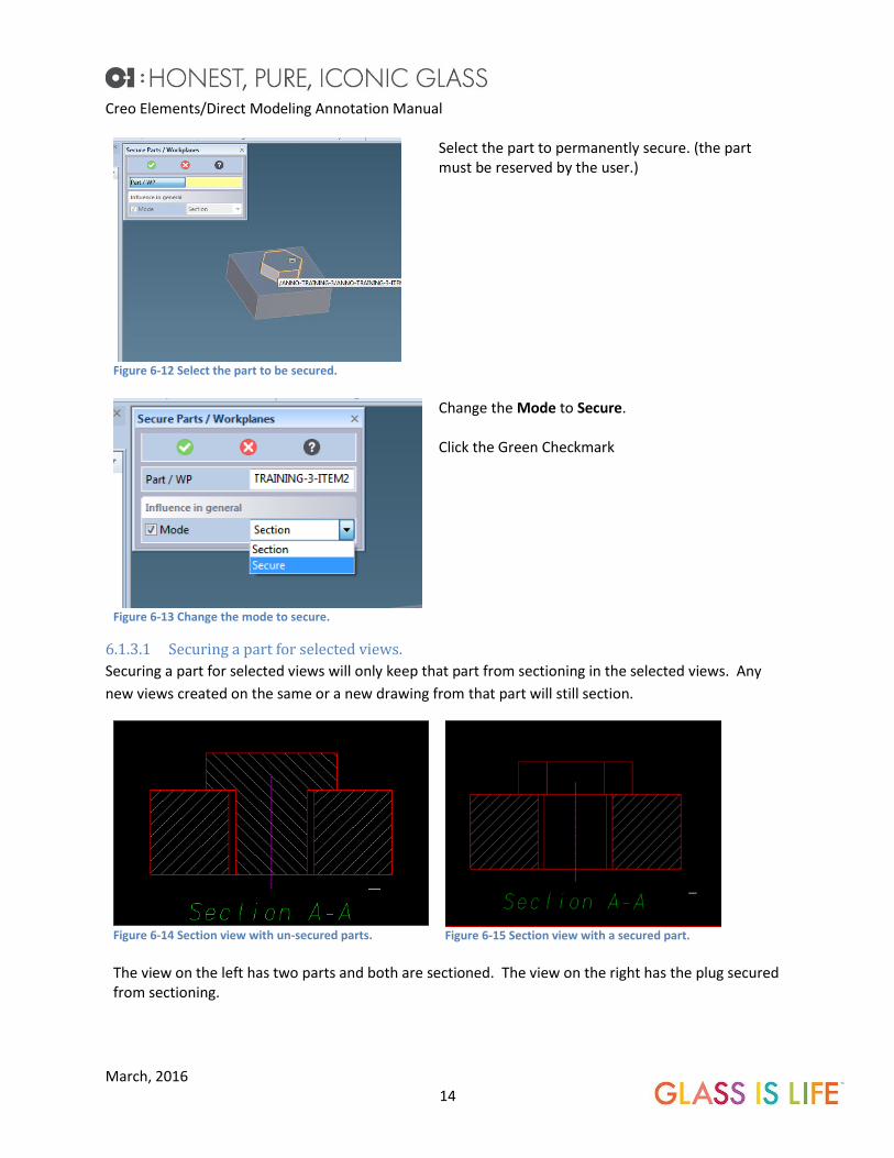
Figure 6-12 Select the part to be secured.
Select the part to permanently secure. (the part must be reserved by the user.)
Figure 6-13 Change the mode to secure.
Change the Mode to Secure. Click the Green Checkmark
6.1.3.1 Securing a part for selected views.
Securing a part for selected views will only keep that part from sectioning in the selected views. Any
new views created on the same or a new drawing from that part will still section.
Figure 6-14 Section view with un-secured parts.
Figure 6-15 Section view with a secured part.
The view on the left has two parts and both are sectioned. The view on the right has the plug secured from sectioning.

Creo Elements/Direct Modeling Annotation Manual
March, 2016 15
Figure 6-16 Secure Part command.
Start the Secure command in annotation by selecing the …More submenu from the Setup menu.
Figure 6-17 Select the Part to be secured.
An Auxilliary 3D viewport opens. Select the part to secure.
Figure 6-18 Secure in all views created with this part.
To keep the part from being sectioned in any drawing created with the part, set the Mode in the Influence in General to Secure. This is typically done with Fasteners. This has the same affect as 6.1.3.1 Securing a part in general.
Figure 6-19 Secure in only the view selected.
To secure a part only in selected views. Keep the Influence in General set to Section. In the Influence per view area, Select the Views where the part is not to be sectioned. Set the Mode in the Influence per view to Secure.

Creo Elements/Direct Modeling Annotation Manual
March, 2016 16
6.1.3.2 Sectioning a secured part.
A part that is Secured using Influence in General will not section in a view. However, this can be easily
overridden by the user.
Figure 6-20 View with a Secured part.
The plug needs to be sectioned, but it is Influenced in General to be secured.
Figure 6-21 Start the Secure command.
Start the Secure command in Annotation.

Creo Elements/Direct Modeling Annotation Manual
March, 2016 17
Figure 6-22 Select the Secured part to be sectioned.
An auxiliary 3D viewport will open. Select the secured part to be Sectioned.
Figure 6-23 Select the view.
Select View under Influence per View and select the view(s) in which the secured part is to be sectioned.
Figure 6-24 Change the Influence per view mode to Section.
Set the Mode under Influence per view to Section. Do Not Change the Influence in general mode.

Creo Elements/Direct Modeling Annotation Manual
March, 2016 18
Figure 6-25 Completed view.
Update the view. The secured part is now section in the selected view.
Detail Views. The detail view command is located on the Mini Toolbar and in the Dep View Menu.
Figure 6-26 Create Detail View command.
Start the Detail View command from the Dep View menu, or from the Mini Toolbar.

Creo Elements/Direct Modeling Annotation Manual
March, 2016 19
Figure 6-27 Detail View Dialog Box .
Click on the parent view from which the detail view is to be made.
Figure 6-28 Pick the border type from the command Dialog Box or right click menu.
Select the type of border. Rectangles, Circles and Polygon type borders are automatically accepted when the border is closed. To complete the spline type border, click Accept in the Dialog Box, or right click and Accept.
Figure 6-29 Draw the border, for splines, right click and accept when complete.
This is a spline type border. After completing the border Right Click and Accept, or click Accept in the Dialog Box. The default view scale is two times the parent view scale. If the parent is 2:1 the detail will be 4:1. This can be overridden by the user.

Creo Elements/Direct Modeling Annotation Manual
March, 2016 20
Figure 6-30 Completed detail view.
Click the Green Checkmark to complete the command and place the detail view.
Partial Views. A partial view is convenient when only a small section of a view is required. When a partial view is
created, all dimensions and annotations on the parent view will be lost.
Figure 6-31 Start the Create Partial View command.
The Create Partial View command is started from the Dep View menu. This can also be added to the Mini Toolbar.
Figure 6-32 Select the Parent view.
Select the Parent View to be converted into a partial view. Note! Please note that all dimensions attached to the Parent View will be lost. It is best to create the partial view early in the drawing process.

Creo Elements/Direct Modeling Annotation Manual
March, 2016 21
Figure 6-33 Spline Border.
Draw the border (done in the same manner as the Create Detail View border)
Figure 6-34 Partial View
Once the border is complete, click the Green Checkmark to finish the command.
In the example above, notice that the secured part did not carry through to the partial view. This is
because the part was only secured to view Section A-A and not the Partial 1 view. If the part was
secured in general, it would not be sectioned in any view.
Partial to Full. The partial view can be converted back into a full view with the Partial to Full command in the Dep View
menu. All dimensions and annotations on the partial view will be lost.

Creo Elements/Direct Modeling Annotation Manual
March, 2016 22
Figure 6-35 Start the command.
Start the Partial to Full command from the Dep View menu.
Figure 6-36 Select the view.
Select the partial view to convert back into a full view.
Figure 6-37 Click continue to change the view to full.
All dimensions on the view will be lost. Click Continue to proceed.

Creo Elements/Direct Modeling Annotation Manual
March, 2016 23
Figure 6-38 Click the Green Checkmark to complete.
Click the Green Checkmark. Update the view if required.
Cutaway Views. Cutaway views show internal features of a part or an assembly that would normally be hidden.
Figure 6-39 Start the command.
Start the Cutaway command from the Dep View menu.
Creo Elements/Direct Modeling Annotation Manual
March, 2016 24
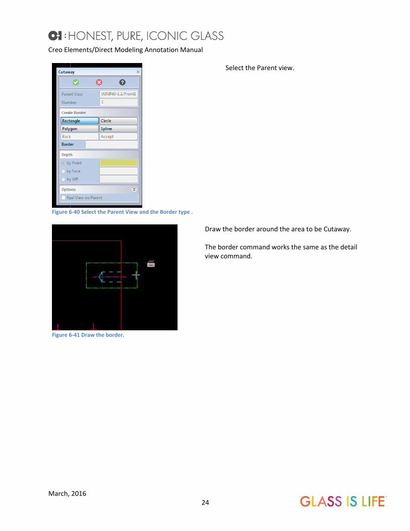
Figure 6-40 Select the Parent View and the Border type .
Select the Parent view.
Figure 6-41 Draw the border.
Draw the border around the area to be Cutaway. The border command works the same as the detail view command.

Creo Elements/Direct Modeling Annotation Manual
March, 2016 25
Figure 6-42 Select the Cutaway to point.
After accepting the border, a 3D auxiliary viewport opens. Select a point, face or Workplane for the depth of the Cut Away.
Figure 6-43 Select the Cut Away depth, by point, face or workplane.
Figure 6-44 Confirm the Cutaway depth and click the Green Checkmark.
Review the Cutaway volume by rotating the part. Click the Green Checkmark to complete the command.
Figure 6-45 The completed view.
The final Cutaway.

Creo Elements/Direct Modeling Annotation Manual
March, 2016 26
Remove Cutaway. Cutaway views can be removed from a view by selecting the Remove Cutaway command and selecting
the cutaway view on the drawing. Any dimensions going to the Cut Away geometry will disconnect and
turn red.
Figure 6-46 Start the command. This command does not have a Dialog Box.
Start the Remove Cutaway command from the Dep View menu. Note! This command differs from many of the other commands because there is no dialog box.
Figure 6-47 Select the Cutaway to be removed.
Select the Cutaway to be removed.
Figure 6-48 Confirm the selection.
Confirm that the Cutaway is to be removed.

Creo Elements/Direct Modeling Annotation Manual
March, 2016 27
Figure 6-49 The completed command.
Update the view if required. The Cutaway is removed from the view. Any dimensions going to geometry within the Cut Away will turn red.
Broken Views. Broken views allow a very long part to fit on a sheet by splitting a view and removing one or more
portions from the view. Care must be taken not to leave important features out.
Figure 6-50 The front view does not fit on the sheet.
In this example the front view of the part is too large to fit on the sheet. The view can be broken to allow it to fit.
Figure 6-51 Start the Broken View command.
Start the Broken View command from the Dep View menu.

Creo Elements/Direct Modeling Annotation Manual
March, 2016 28
Figure 6-52 Broken View Dialog Box.
Select the View to be broken
Figure 6-53 Place the gaps on the view. A Vertical gap is shown.
Select the gap to be removed for the break by clicking on Horizontal or Vertical . Multiple gaps can be created. In this example, the Vertical gap was chosen. Drag the arrows to change the size of the break. Hint: Creating a workplane in modeling with lines evenly spaced, can be used to create very precise breaks (gaps). The Border is the shape of the spline use to represent the cutaway in the view. The default border works well for most situations.
Figure 6-54 The final broken view.
Select the Green Checkmark and update the view if required. The gaps can be edited by restarting this command.
Creo Elements/Direct Modeling Annotation Manual
March, 2016 29
Dependent General Views. Dependent General Views allows the creation of auxiliary views from an existing view. The Dependent
General view will keep the attributes of the parent view.
Figure 6-55 Start the command.
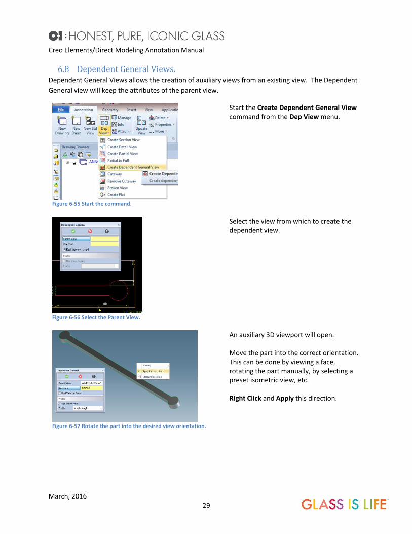
Start the Create Dependent General View command from the Dep View menu.
Figure 6-56 Select the Parent View.
Select the view from which to create the dependent view.
Figure 6-57 Rotate the part into the desired view orientation.
An auxiliary 3D viewport will open. Move the part into the correct orientation. This can be done by viewing a face, rotating the part manually, by selecting a preset isometric view, etc. Right Click and Apply this direction.

Creo Elements/Direct Modeling Annotation Manual
March, 2016 30
Figure 6-58 Completed view.
Position the view and click the Green Checkmark. Update the view if required. Note that the Dependent General view keeps the attributes of the parent view including the break.
7 Updating Views. The color of the text in the Drawing Browser indicates the state of the views in comparison to the
model.
Dark Blue: Updated
Cyan: Needs Updated
Red: The 3D model is not loaded, or the drawing is not linked to a loaded viewset.
Black: No Model is associated to the drawing, such as a Target Sheet.
Figure 7-1 Color Update Status
When views required an update (cyan text) there are several options there are several options.
All of the views can be updated at once by clicking on the Update Drawing icon. from the O-I
Annotation Utilities toolbar, or right clicking on the Drawing Title in the Drawing browser, and selecting
Update all Views.
Sheets can be updated by right clicking the Sheet in the Drawing Browser and selecting Update all
Views.
Individual views can be updated by right clicking the View Name in the Drawing Browser and selecting
Update View. Or the view itself can be picked and click on the Update View from the Mini Toolbar.

Creo Elements/Direct Modeling Annotation Manual
March, 2016 31
Figure 7-2 Update all Views on the drawing
Figure 7-3 Update all Views on a selected sheet
Figure 7-4 Update View, Mini Toolbar
8 Moving Views. Views can be moved by selecting the view and dragging. To line up with other views, pick the view to
be moved and hover over those views to align to. Green guide lines will pop up as a guide to indicate
view centers. Move the view until the magenta center dot aligns to the green guide lines. See Also 30.1
Fixing the View Reference Points.
For some auxiliary views, it is necessary to create construction lines and move the view by 2 points.
Figure 8-1 Hovering over other views displays alignment lines.
Moving views between sheets. A view can be moved from one sheet to another on multiple sheet drawings.
Creo Elements/Direct Modeling Annotation Manual
March, 2016 32
Figure 8-2 Start the Move command.
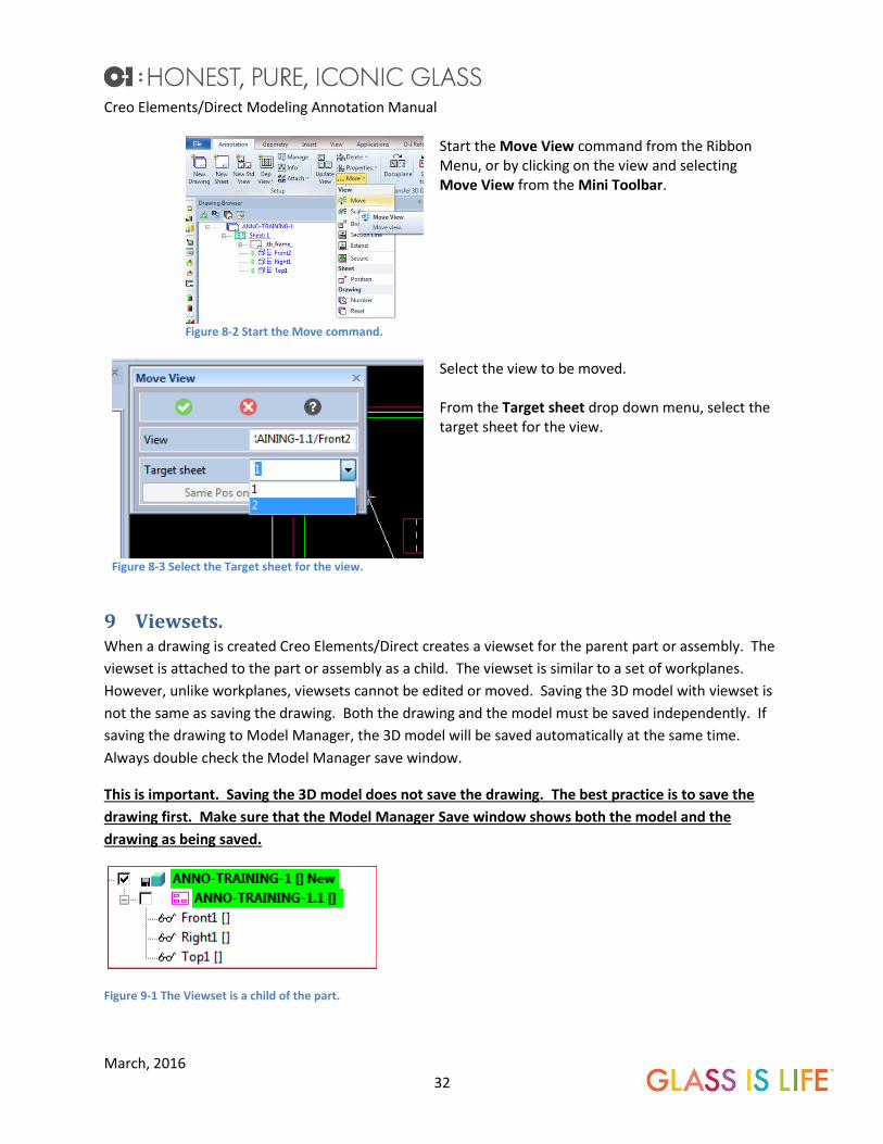
Start the Move View command from the Ribbon Menu, or by clicking on the view and selecting Move View from the Mini Toolbar.
Figure 8-3 Select the Target sheet for the view.
Select the view to be moved. From the Target sheet drop down menu, select the target sheet for the view.
9 Viewsets. When a drawing is created Creo Elements/Direct creates a viewset for the parent part or assembly. The
viewset is attached to the part or assembly as a child. The viewset is similar to a set of workplanes.
However, unlike workplanes, viewsets cannot be edited or moved. Saving the 3D model with viewset is
not the same as saving the drawing. Both the drawing and the model must be saved independently. If
saving the drawing to Model Manager, the 3D model will be saved automatically at the same time.
Always double check the Model Manager save window.
This is important. Saving the 3D model does not save the drawing. The best practice is to save the
drawing first. Make sure that the Model Manager Save window shows both the model and the
drawing as being saved.
Figure 9-1 The Viewset is a child of the part.
Creo Elements/Direct Modeling Annotation Manual
March, 2016 33
10 Attaching a drawing to a variant. Attaching a drawing to a variant allows an existing drawing to be copied and attached to a new part.
The views in the new drawing will attach to the new part and update with it.
If the new part does not have a viewset, Attach to Variant will copy the viewset from the base model to
the new model.
Note: If the new part does not have a viewset (or copied form the original part) attached make sure that
the original model and the new model are aligned with each prior to using “Copy Variant”. Otherwise
the viewsets may not be aligned to the part correctly and the drawing will be incorrect.
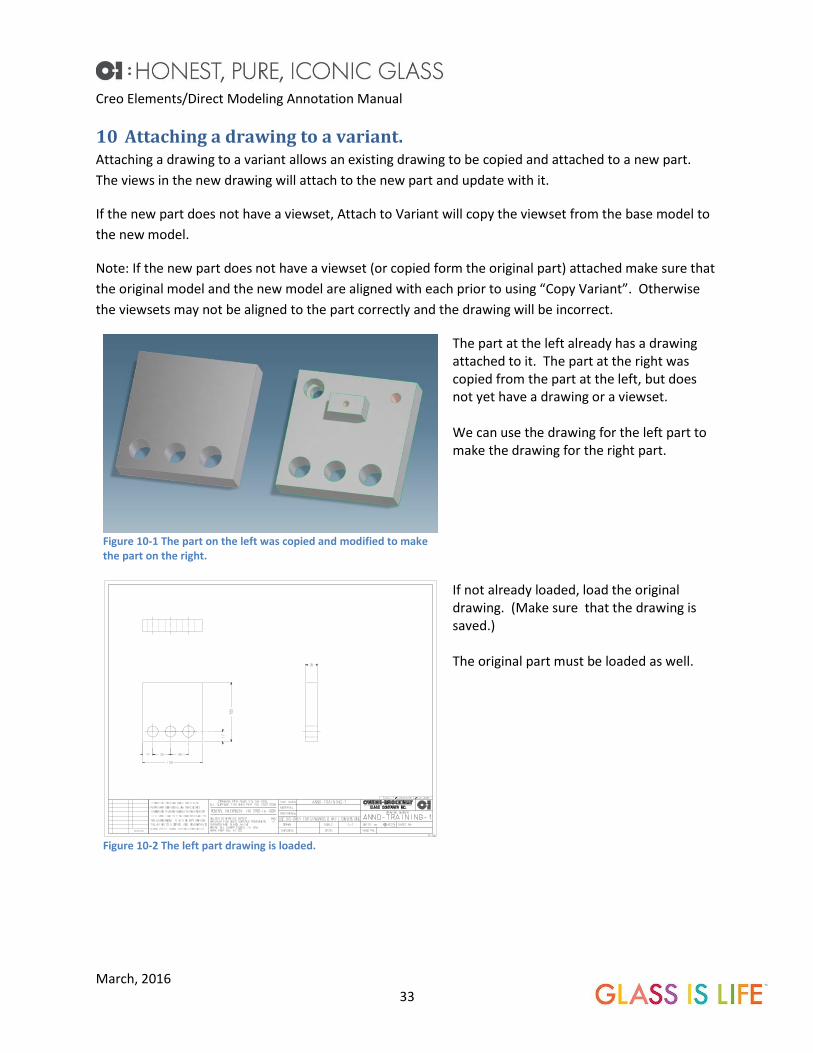
Figure 10-1 The part on the left was copied and modified to make the part on the right.
The part at the left already has a drawing attached to it. The part at the right was copied from the part at the left, but does not yet have a drawing or a viewset. We can use the drawing for the left part to make the drawing for the right part.
Figure 10-2 The left part drawing is loaded.
If not already loaded, load the original drawing. (Make sure that the drawing is saved.) The original part must be loaded as well.

Creo Elements/Direct Modeling Annotation Manual
March, 2016 34
Figure 10-3 Start the attached to Variant command.
Start the Attach to Variant command.
Figure 10-4 If the drawing is saved, continue.
If the drawing is saved, click Continue, otherwise Cancel, save and start again.
Figure 10-5 Select the part to attach the drawing.
The Original Model should be selected by default, select the Original Model from the Structure Browser. Select the Target Model from the Structure Browser.
Figure 10-6 Continue to copy the existing viewset.
If the new part does not have its own view set, click Continue to copy the viewset from the old model to the new model. If the new model already has a viewset, then this window will not appear.
Figure 10-7 Finish the command.
Select any options desired, and click the green checkmark to create the new drawing.

Creo Elements/Direct Modeling Annotation Manual
March, 2016 35
Figure 10-8 The new drawing.
Update the drawing, and edit as needed. If the views move drastically and it is difficult to align them, see Appendix 30.1
FIXING THE VIEW REFERENCE POINTS.
11 Attach a drawing to a copy. This command should not be used. Instead, use the Copy to Variant.
12 Attach a drawing to Mirror. A drawing can be attached to a mirror of the part. All of the dimensions and special views created in the
original drawing will be transferred to the mirrored drawing. A few important notes here. First, the
original part and drawing must be created first. Then the 3D model of the part can be mirrored. After
that, the drawing can be attached to the mirror.
Figure 12-1 Original Part.
Start with the original part.
Creo Elements/Direct Modeling Annotation Manual
March, 2016 36
Figure 12-2 Original drawing for the Original Part.
Create the drawing for the original part. Add any dimensions, dependent views and sections required. Save the Drawing!
Figure 12-3 Create a mirror of the original part.
Create a mirror of the original part.
Figure 12-4 Start the command.
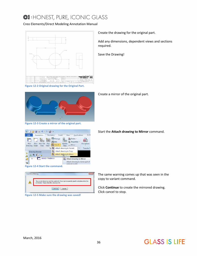
Start the Attach drawing to Mirror command.
Figure 12-5 Make sure the drawing was saved!
The same warning comes up that was seen in the copy to variant command. Click Continue to create the mirrored drawing. Click cancel to stop.

Creo Elements/Direct Modeling Annotation Manual
March, 2016 37
Figure 12-6 Select the mirrored model for the Target.
The Original Model should be selected by default, if not select the Original Model from the structure browser. Select the Target Model, this is the mirror part that was just created. Click the Green Checkmark to complete.
Figure 12-7 The completed mirrored drawing with all of the dimensions.
Update the drawing. If the views move drastically and it is difficult to align them, see Appendix 30.1 FIXING THE VIEW
REFERENCE POINTS.
13 View Properties. View properties define the view scale, angle, label information, the update mode, visibility options, line
appearance, if all parts are displayed in a view, if full circles are displayed in a view, how sections are
transferred and shown, if a secured part will be honored, and shading techniques.
The View Profiles automatically will set view properties for a view based on how may parts are in the
view.
To modify a view’s properties, click on the view and select view properties from the Mini Toolbar

Creo Elements/Direct Modeling Annotation Manual
March, 2016 38
Figure 13-1 General Page.
This is the View Properties Dialog box. The General page has the view title, scale and view angle.
Figure 13-2 Calc Mode Page.
The Calc Mode page defines how a view updates. See Chapter 14 Calc Modes for more information. Clash handling is important. This will check if parts clash and will use the defined clash method for the part in the drawing. Leave this at its default setting. See 3D best practices for an explanation of Press Fits. If any of the Shaded options are selected for the Calc Mode, an additional “Shaded” page will be added.
Creo Elements/Direct Modeling Annotation Manual
March, 2016 39
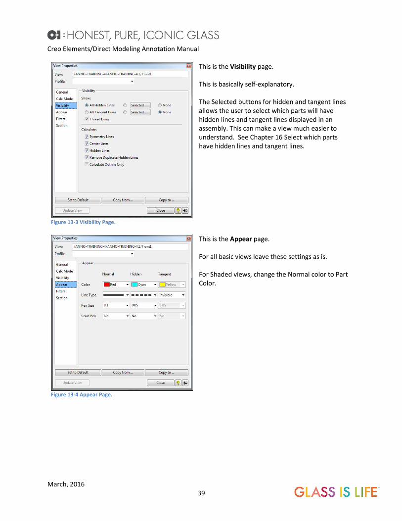
Figure 13-3 Visibility Page.
This is the Visibility page. This is basically self-explanatory. The Selected buttons for hidden and tangent lines allows the user to select which parts will have hidden lines and tangent lines displayed in an assembly. This can make a view much easier to understand. See Chapter 16 Select which parts have hidden lines and tangent lines.
Figure 13-4 Appear Page.
This is the Appear page. For all basic views leave these settings as is. For Shaded views, change the Normal color to Part Color.

Creo Elements/Direct Modeling Annotation Manual
March, 2016 40
Figure 13-5 Filters Page.
This is the Filters page Small parts can be removed automatically from a view. This is good for very large assemblies where a small part will not even be seen. Leave the full circles as it is, otherwise all circles will be drawn as an arc. This confuses the views.
Figure 13-6 Section Page.
This is the Section page. Handling of Sectioned Parts and Workplanes: On – all secured parts will be displayed as secured, any parts in front of the section view will not be displayed. On Include all parts in front of the section plane. – This will show all secured parts in the view even if they are in front of the sectioned view. Off- This will section all secured parts. Calculations including : Previous Sections: Yes will add the previous section to the new section view. No, will not include any previous sections Previous Cutaways: Yes, will add any existing cutaways to the section view. No will ignore the existing Cutaways for the section view.
Creo Elements/Direct Modeling Annotation Manual
March, 2016 41
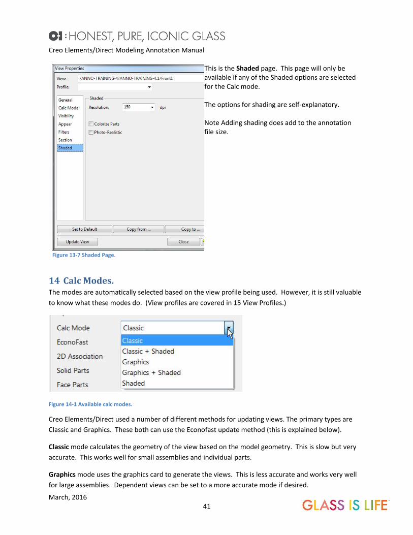
Figure 13-7 Shaded Page.
This is the Shaded page. This page will only be available if any of the Shaded options are selected for the Calc mode. The options for shading are self-explanatory. Note Adding shading does add to the annotation file size.
14 Calc Modes. The modes are automatically selected based on the view profile being used. However, it is still valuable
to know what these modes do. (View profiles are covered in 15 View Profiles.)
Figure 14-1 Available calc modes.
Creo Elements/Direct used a number of different methods for updating views. The primary types are
Classic and Graphics. These both can use the Econofast update method (this is explained below).
Classic mode calculates the geometry of the view based on the model geometry. This is slow but very
accurate. This works well for small assemblies and individual parts.
Graphics mode uses the graphics card to generate the views. This is less accurate and works very well
for large assemblies. Dependent views can be set to a more accurate mode if desired.
Creo Elements/Direct Modeling Annotation Manual
March, 2016 42
When Econofast is turned on, the views are quickly calculated using the graphics card, this is only to
determine what parts are hidden. The views are then created using the selected mode above.
In addition to the above modes, shading can be added which creates a fully shade “3D” image for a
view. It is recommended to use either Classic + Shaded or Graphics + Shaded as the include the part
geometry in the view. Shaded does not include part geometry. Balloons, text and dimensions can only
be attached to geometry. Change the part geometry to Part Color to “hide” the geometry. See Figure
13-4.
15 View Profiles. View profiles are automatically selected based on the number of parts in the view that is being created.
View profiles are defined in the company configuration and are not user customizable.
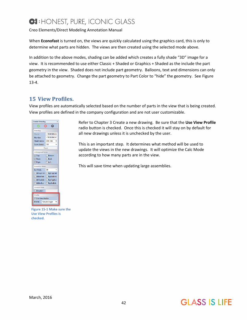
Figure 15-1 Make sure the Use View Profiles is checked.
Refer to Chapter 3 Create a new drawing. Be sure that the Use View Profile radio button is checked. Once this is checked it will stay on by default for all new drawings unless it is unchecked by the user. This is an important step. It determines what method will be used to update the views in the new drawings. It will optimize the Calc Mode according to how many parts are in the view. This will save time when updating large assemblies.

Creo Elements/Direct Modeling Annotation Manual
March, 2016 43
The view profile sets the following. Update mode
Turns on or off Econofast
Sets 2D associativity
Sets whether or not views update immediately or manually
Set how circles are displayed (full or Limited) (full by default)
Sets if duplicate hidden lines are removed (removed by default)
Turns on or off thread creation
Sets centerline creation
Sets symmetry line creation
Sets hidden lines on or off
Sets tangent lines on or off
Small drawings and assemblies use the slowest update modes for the highest accuracies. Hidden lines,
centerlines and symmetry lines are displayed. As the number of parts increase in the assembly, the
faster and less accurate the calc mode selected. These views will not have hidden lines, centerlines or
symmetry lines shown.
Keep in mind, that disabling the “Use View Profile” will affect the update performance. See chapter 29
IMPROVING UPDATE PERFORMANCE. The user is able to override the default selection and select a different
profile.
16 Select which parts have hidden lines and tangent lines. Large assembly drawings can be very confusing if all of the hidden lines of all the parts are shown.
Annotation allows the user to select which parts will have hidden lines displayed in a view on an
assembly drawing. This make the views much more clear.
Tangent lines can be applied to individual parts of the assembly view as well.
The instructions below relate to showing hidden lines on specific parts. The tangent lines visibility works
the same way.

Creo Elements/Direct Modeling Annotation Manual
March, 2016 44
Figure 16-1 All parts show hidden lines.
All of the parts in this view have hidden lines shown. Fortunately, this is a simple view and hidden lines are not overly confusing. Despite this, lets only show the hidden lines in the tube.
Figure 16-2 Open the View Properties.
Click the view and select View Properties form the Mini Toolbar
Figure 16-3 Click the Selected button.
Click the Selected Button on the All Hidden Lines line.
Creo Elements/Direct Modeling Annotation Manual
March, 2016 45
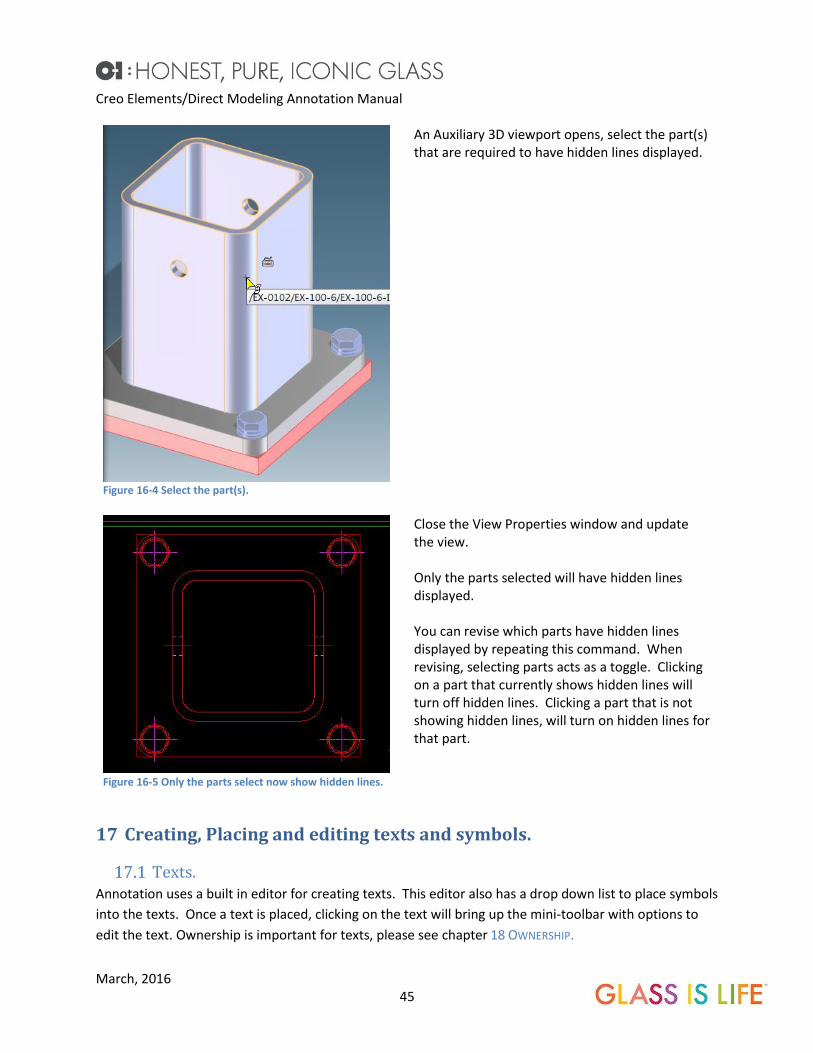
Figure 16-4 Select the part(s).
An Auxiliary 3D viewport opens, select the part(s) that are required to have hidden lines displayed.
Figure 16-5 Only the parts select now show hidden lines.
Close the View Properties window and update the view. Only the parts selected will have hidden lines displayed. You can revise which parts have hidden lines displayed by repeating this command. When revising, selecting parts acts as a toggle. Clicking on a part that currently shows hidden lines will turn off hidden lines. Clicking a part that is not showing hidden lines, will turn on hidden lines for that part.
17 Creating, Placing and editing texts and symbols.
Texts. Annotation uses a built in editor for creating texts. This editor also has a drop down list to place symbols
into the texts. Once a text is placed, clicking on the text will bring up the mini-toolbar with options to
edit the text. Ownership is important for texts, please see chapter 18 OWNERSHIP.

Creo Elements/Direct Modeling Annotation Manual
March, 2016 46
Figure 17-1 Ribbon Menu
To place new text, start the Text New command from the Text menu on the Ribbon Bar. Or Right Click on the screen and select Text New from the Text and Symbols menu..
Figure 17-2 Right Click Menu.
Figure 17-3 Create Text command.
This is the Create Text dialog box that opens when the Text New command is started. Select the Owner of the text. Clicking on the Text button to open the internal editor. (Short texts can be entered directly into the yellow box.)

Creo Elements/Direct Modeling Annotation Manual
March, 2016 47
Figure 17-4 Internal Text Editor window.
This is the text editor window. Note! There is not a built in spell checker. An option is to enter the text into Microsoft Word to spell check, then cut and paste into this Text Editor. Click the Spec Chars button to open up the symbols library.
Figure 17-5 Special Character Browser.
These are the Special Character symbols. These will place the shown symbol codes into the text. When the text is placed on the drawing, the symbol will show. For example to show a diameter symbol, click on Diameter. The symbol code <Diameter> will be shown in the text editor window. When the text is placed on the drawing, Annotation will show the symbol Ø.

Creo Elements/Direct Modeling Annotation Manual
March, 2016 48
Figure 17-6 Placing the leader.
Once text is placed, a leader line can be added to the text by clicking the Ref Line button.
Figure 17-7 Text Templates
Texts that are use often have been made into text templates. Open the template browser and double click the required text to be placed in the drawing. Please see Chapter 2 BROWSER BAR. Many vendor addresses have been saved as templates. These then can be placed on the drawing by selecting the template.
Symbols. Symbols are found in the template browser. Some of these symbols have text fields that can be filled in
by the user. The symbol edit box opens if these fields are available for the user to put in values.
Ownership of symbols is very important.

Creo Elements/Direct Modeling Annotation Manual
March, 2016 49
c Figure 17-8 Symbols Templates.
Click the Template browser button in the Browser Bar. This opens up the symbols and text templates list. (See CHAPTER 2 BROWSER BAR.)
Figure 17-9 Select the Symbol and place it on the drawing.
Select the symbol required. Select the Owner. Place the symbol on the drawing. The text field cannot be edited until the text has been placed.

Creo Elements/Direct Modeling Annotation Manual
March, 2016 50
Figure 17-10 Edit the symbol field(s).
Edit the text. If a Ref Line is needed, click the Ref Line Button. Ref Line is owner dependent. The owner must be a view or sketch in order to have a reference line. In this example, the Ref Line option is greyed out because the owner is the Act Sheet. Click the Green Checkmark.
Figure 17-11 Placed and edited symbol.
Once the Checkmark is clicked the symbol will show the edited text. Clicking on the symbol will bring up a mini-toolbar with options to edit the symbol. Clicking on Position Next Symbol allows the user to place the next symbol on the drawing.
18 Ownership. Placing a symbol or texts on a drawing requires an owner. The owner can be a view, sketch, the active
drawing, or the frame (border).
Ownership is very important.
Texts and symbols cannot have a leader if they are not owned by a view or a sketch.
Symbols such as surface finish will not move with a view if they are not owned by the view.
When placing texts, or symbols make sure that the correct owner is shown in the owner box.
To specify an Owner, click the Owner button, then click the view, sketch or an empty part of the drawing
to select the Active sheet.

Creo Elements/Direct Modeling Annotation Manual
March, 2016 51
Changing the owner of a symbol or text.
Figure 18-1 Modify the text owner.
The owner of a symbol or text can be modified. Click the text or symbol, select Modify Position from the Mini Toolbar. Expand the Change Owner dialog. Select the new owner type, view, sheet etc. If the text or symbol does not have to be moved, click Change Owner + Keep Position button to complete the command.
19 Linear Dimensioning. Dimensioning will be divided into several topics. Linear dimensioning, coordinate dimensioning and
dimensioning features such as holes, fillets and blends.
Sometimes dimensions (particularly coordinate) dimensions are packed so tightly, they are difficult to
read.
Single dimensions. Single dimension places a dimension from a start point to a finish point.
Figure 19-1 Start the Single Dim command.
Start the Single Dim command.

Creo Elements/Direct Modeling Annotation Manual
March, 2016 52
Figure 19-2 Start dimensioning line to line or point to point.
Select the base and the first dimensioned geometry. Once a dimension is placed, additional dimension can be added. Hint: Try to select line segments instead of points, this will help align the dimension as well as update correctly if surfaces are moved in future revisions. Hint: if the dimension is oriented incorrectly, right click and select the correct orientation.
Figure 19-3 Hovering on an existing dimension displays alignment snaps.
Hovering over an existing dimension will bring up placement points so that the new dimension can be placed in line with the existing dimension or spaced equally above or below the dimension.
Figure 19-4 Aligned dimension.
The dimensions snaps in line with the placement points.
Tangential linear dimensioning. The circular dimensioning toolbar includes the tangential dimension command. This command can be
used to dimension between a radius and linear geometry and between to radial surfaces.
Creo Elements/Direct Modeling Annotation Manual
March, 2016 53
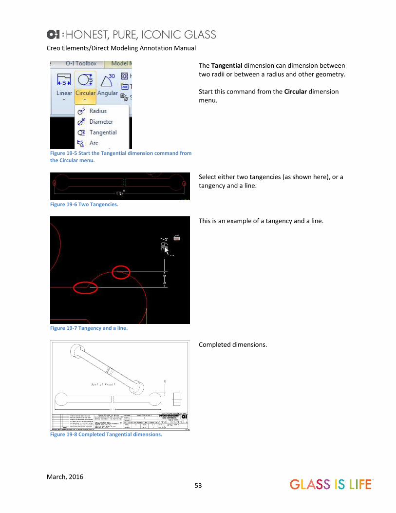
Figure 19-5 Start the Tangential dimension command from the Circular menu.
The Tangential dimension can dimension between two radii or between a radius and other geometry. Start this command from the Circular dimension menu.
Figure 19-6 Two Tangencies.
Select either two tangencies (as shown here), or a tangency and a line.
Figure 19-7 Tangency and a line.
This is an example of a tangency and a line.
Figure 19-8 Completed Tangential dimensions.
Completed dimensions.

Creo Elements/Direct Modeling Annotation Manual
March, 2016 54
Datum Long. Datum long dimensioning works similar to Chain dimensioning. The difference, all of the dimension
start from the same point.
Figure 19-9 Start the Datum Long command.
Start the Datum Long command.
Figure 19-10 Select the base point and items to be dimensioned.
Select the start point and the first geometry to be dimensioned.
Figure 19-11 Finished dimensions.
Continue selecting geometry in the same direction. The dimension start at the start point and end at the selected geometry automatically spacing.
Datum Short A Datum Short dimension displays the distance from a start point to an end point. However only the end
arrow and dimension are shown.
Creo Elements/Direct Modeling Annotation Manual
March, 2016 55
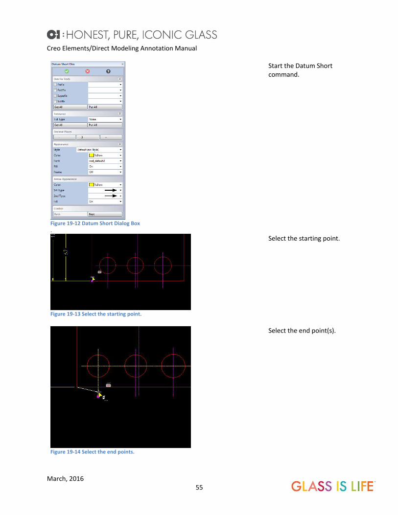
Figure 19-12 Datum Short Dialog Box .
Start the Datum Short command.
Figure 19-13 Select the starting point.
Select the starting point.
Figure 19-14 Select the end points.
Select the end point(s).

Creo Elements/Direct Modeling Annotation Manual
March, 2016 56
Figure 19-15 Completed command.
This is an example of Datum short.
Chain Dimensioning. Chain dimensioning allows the creation of a group of dimensions with all of the dimensions aligned or
spaced properly.
Figure 19-16 Start the Chain Dim command.
Start the Chain Dim command.

Creo Elements/Direct Modeling Annotation Manual
March, 2016 57
Figure 19-17 Place dimensions.
Select the start point and end point of the first dimension. The start of the second dimension will automatically continue from the end of the first dimension. Continue selecting new end points to chain the dimensions together. The previous end point becomes the start point for the next dimension.
Figure 19-18 Continue selecting dimension end points.
This is a series of chained dimensions.
Coordinate Dimension. The coordinate dimensions work off a base point. Typically the base point is on the same view as the
dimensions. External Base Points will be discussed in chapter 19.6.1 EXTERNAL BASE POINTS.

Creo Elements/Direct Modeling Annotation Manual
March, 2016 58
. Figure 19-19 Start the Coordinate Dimension command.
Start the Coordinate command.
Figure 19-20 Select the base point.
Click the base point. (Note that in this example, the 0 dimension is not displayed.)

Creo Elements/Direct Modeling Annotation Manual
March, 2016 59
Figure 19-21 Select the first dimension and correct the alignment.
Select the first geometry to be dimensioned. Correct the dimension alignment if necessary by right clicking.
Figure 19-22 Continue selecting geometry to dimension.
Continue to add dimensions until complete.
Figure 19-23 Finished Dimensions
Completed dimensioning.
19.6.1 External Base Points.
External base points allow the zero point from one view to be transferred to another view, such as a
detail view. The view where the external point is selected and the view being dimension must have the
same perspective.

Creo Elements/Direct Modeling Annotation Manual
March, 2016 60
Figure 19-24 Add coordinate dimensions to Detail 1 using the same basepoint as the front view .
Figure 19-25 Check the External Base Pnt checkmark.
Start the Coordinate dimension command and click the External Base Pnt radio button.

Creo Elements/Direct Modeling Annotation Manual
March, 2016 61
Figure 19-26 Select the base point of the source view.
Select the base point of the source view. This is the point on the geometry that the dimension is attached.
Figure 19-27 Select the target feature and ensure the dimension orientation.
Select the object to be dimensioned in the target view. Ensure that the dimension is oriented correctly (right click).
Figure 19-28 Continue dimensioning as required.
Continue adding dimensions to the target view as required.

Creo Elements/Direct Modeling Annotation Manual
March, 2016 62
Figure 19-29 Completed coordinate dimensioning.
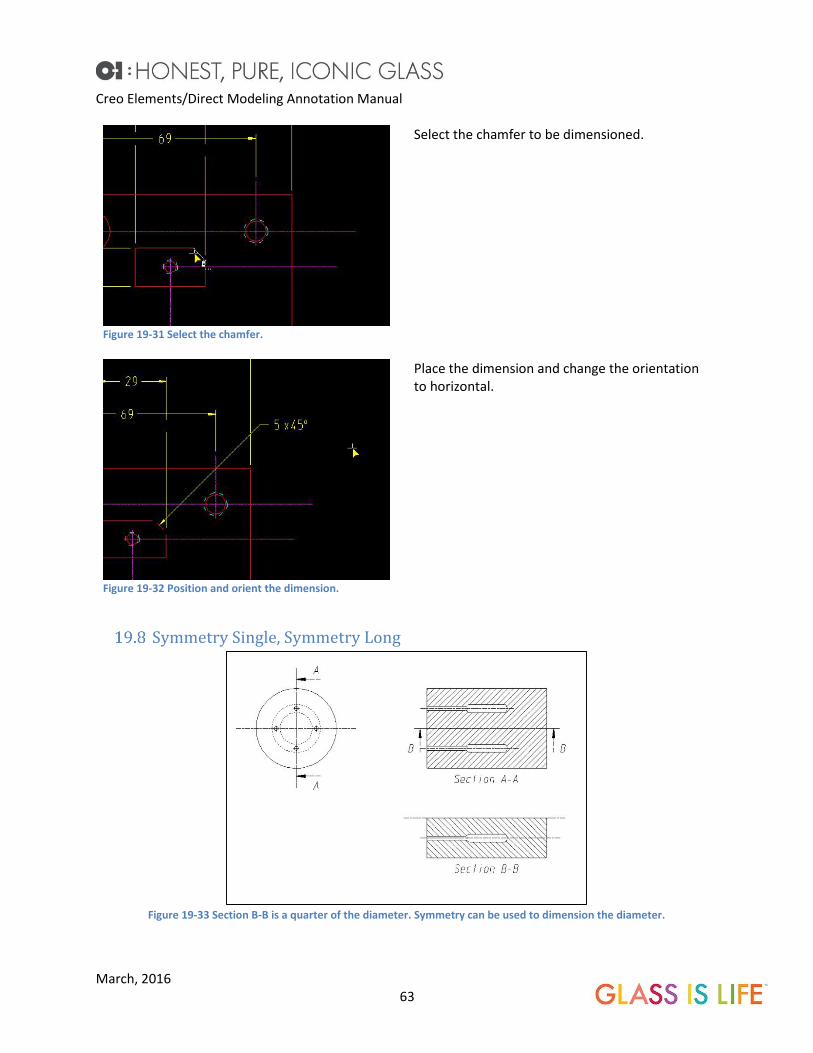
Chamfer The chamfer dimension is used for 45° chamfers only. It Will not work on any other angle of chamfer.
Figure 19-30 Chamfer Dim menu.
Start the Chamfer Dim command. Note that the postfix x45° is automatically selected.
Creo Elements/Direct Modeling Annotation Manual
March, 2016 63
Figure 19-31 Select the chamfer.
Select the chamfer to be dimensioned.
Figure 19-32 Position and orient the dimension.
Place the dimension and change the orientation to horizontal.
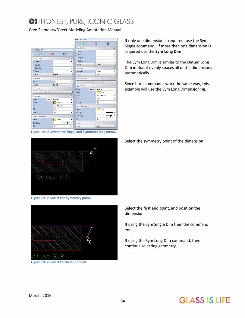
Symmetry Single, Symmetry Long
Figure 19-33 Section B-B is a quarter of the diameter. Symmetry can be used to dimension the diameter.
Creo Elements/Direct Modeling Annotation Manual
March, 2016 64
Figure 19-34 Symmetry Single and Symmetry long menus.
If only one dimension is required, use the Sym Single command. If more than one dimension is required use the Sym Long Dim. The Sym Long Dim is similar to the Datum Long Dim in that it evenly spaces all of the dimensions automatically. Since both commands work the same way, this example will use the Sym Long Dimensioning.
Figure 19-35 Select the Symmetry point.
Select the symmetry point of the dimension.
Figure 19-36 Select the first endpoint.
Select the first end point, and position the dimension. If using the Sym Single Dim then the command ends. If using the Sym Long Dim command, then continue selecting geometry.

Creo Elements/Direct Modeling Annotation Manual
March, 2016 65
Figure 19-37 Continue selecting endpoints.
If using the Sym Long Dim, continue selecting end points. (note that the Ø symbol was manually added
to the prefix.)
Figure 19-38 Completed command.
The completed command.
Put Dim In /Take Dim Out. The major advantage of Chain, Coordinate, and Datum Long dimensioning is the ability to add and
remove dimensions to the group. The other dimensions automatically move to keep proper spacing.
For example if a series of holes is dimensioned and a hole is added, a dimension can be added to a chain,
coordinate or datum dimension.

Creo Elements/Direct Modeling Annotation Manual
March, 2016 66
19.9.1 Take Dim Out Datum Long Dimensions.
Figure 19-39 Take Dim Out command.
Start the Take Dim Out command.
Figure 19-40 Select the dimension.
Select the dimension to be removed from the Datum Long group.
Figure 19-41 The dimensions move to keep spacing.
The Dimensions will automatically respace to the default spacing.

Creo Elements/Direct Modeling Annotation Manual
March, 2016 67
19.9.2 Put Dim In for Datum Long Dimensioning.
Figure 19-42 Start the Put Dim In command.
Start the Put Dim In command.
Figure 19-43 Select the Dimension Group.
Select the Dim group by selecting any of the dimensions in the Datum Long dimension group.

Creo Elements/Direct Modeling Annotation Manual
March, 2016 68
Figure 19-44 Select the Geometry.
Select the geometry to be dimensioned.
Figure 19-45 The Dimensions move to make room for the new dimension.
The dimensions move to make room for the new dimensions keeping the default spacing.
19.9.3 Take Dim Out for Chain Dimensioning.
The example in 19.5 CHAIN DIMENSIONING. missed dimensioning a hole, and dimensions the edge of the
boss instead.
Figure 19-46 The boss is dimensioned and a hole is missed.
Creo Elements/Direct Modeling Annotation Manual
March, 2016 69
Figure 19-47 Start the Take Dim Out command.
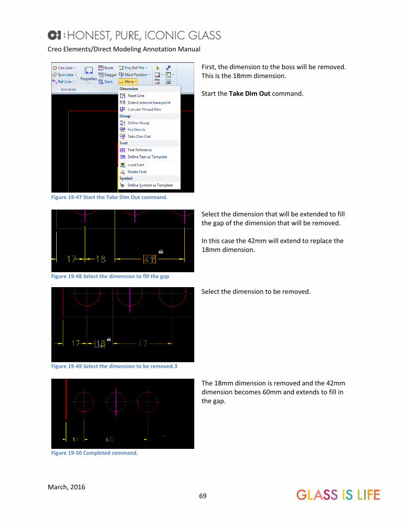
First, the dimension to the boss will be removed. This is the 18mm dimension. Start the Take Dim Out command.
Figure 19-48 Select the dimension to fill the gap .
Select the dimension that will be extended to fill the gap of the dimension that will be removed. In this case the 42mm will extend to replace the 18mm dimension.
Figure 19-49 Select the dimension to be removed.3
Select the dimension to be removed.
Figure 19-50 Completed command.
The 18mm dimension is removed and the 42mm dimension becomes 60mm and extends to fill in the gap.

Creo Elements/Direct Modeling Annotation Manual
March, 2016 70
19.9.4 Put Dim In for Chain Dimensions.
Dimensions can be added into a chain.
Figure 19-51 The center hole needs to be added to the dimension chain
Now the center hole dimension needs to be added into the chain.
Figure 19-52 Start the Put Dim In command.
Start the Put Dim In command.
Figure 19-53 Select the dimension chain.
Select the dimension chain to add the dimension.

Creo Elements/Direct Modeling Annotation Manual
March, 2016 71
Figure 19-54 Select the object to be added to the chain .
Select the object to be dimensioned.
Figure 19-55 The dimension is inserted into the chain.
The dimensions move over and the new dimension is added into the chain.
19.9.5 Put Dim In and Take Dim Out for Coordinate Dimensions.
Figure 19-56 Start the Insert Dim command and select the dimension group.
Put Dim In will add dimensions to the coordinate dimension group. Start the Put Dim In command. Select the Dim Group. Select any of the dimensions in the group. (for this example any of the horizontal dimensions.)

Creo Elements/Direct Modeling Annotation Manual
March, 2016 72
Figure 19-57 Select the base point.
Select the geometry to be dimensioned. In this example the base point is select to add the 0 coordinate.
Figure 19-58 The 0 dimension is added.
The zero dimension is now added.
20 Circular Dimensioning.
Radii.
Creo Elements/Direct Modeling Annotation Manual
March, 2016 73
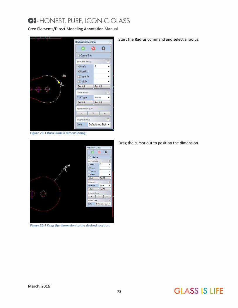
Figure 20-1 Basic Radius dimensioning.
Start the Radius command and select a radius.
Figure 20-2 Drag the dimension to the desired location.
Drag the cursor out to position the dimension.

Creo Elements/Direct Modeling Annotation Manual
March, 2016 74
Figure 20-3 Centerline option.
Clicking the Centerline radio button, extends the extension line to the radius centerline.
Figure 20-4 Finished dimension.
The text is in line with the extension line. Since the center of this radius is within the part, it should be made horizontal. There are two methods to change this.
Creo Elements/Direct Modeling Annotation Manual
March, 2016 75
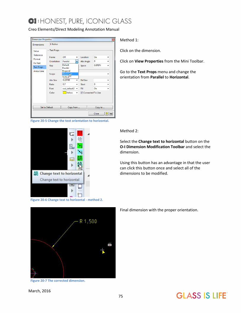
Figure 20-5 Change the text orientation to horizontal.
Method 1: Click on the dimension. Click on View Properties from the Mini Toolbar. Go to the Text Props menu and change the orientation from Parallel to Horizontal.
Figure 20-6 Change text to horizontal - method 2.
Method 2: Select the Change text to horizontal button on the O-I Dimension Modification Toolbar and select the dimension. Using this button has an advantage in that the user can click this button once and select all of the dimensions to be modified.
Figure 20-7 The corrected dimension.
Final dimension with the proper orientation.
Creo Elements/Direct Modeling Annotation Manual
March, 2016 76
Figure 20-8 Arc extension example.
Annotation will automatically place an arc extension on the dimension, if the dimension is not directly pointing to the radius.
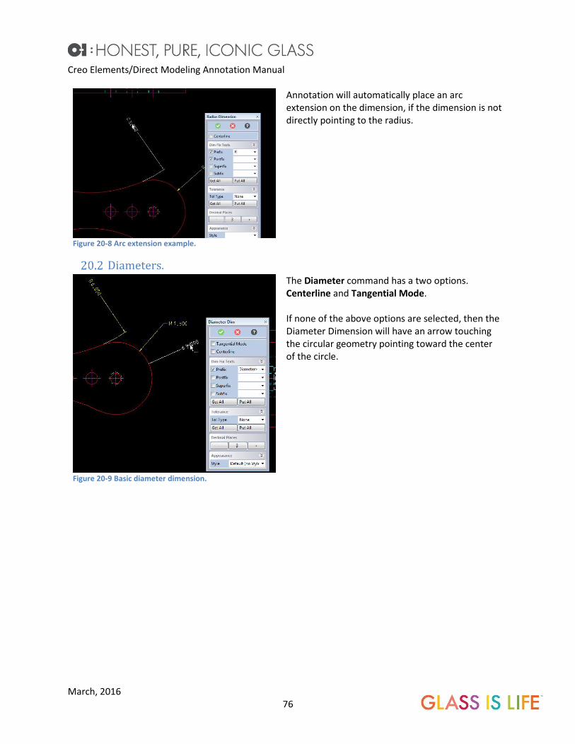
Diameters.
Figure 20-9 Basic diameter dimension.
The Diameter command has a two options. Centerline and Tangential Mode. If none of the above options are selected, then the Diameter Dimension will have an arrow touching the circular geometry pointing toward the center of the circle.

Creo Elements/Direct Modeling Annotation Manual
March, 2016 77
Figure 20-10 Centerline option.
The Centerline option will draw the extension line through the center of the diameter. If the diameter is a 180° arc where the dimension touches, two arrows will be shown. If the diameter is not a 180° arc where the dimension touches, only one arrow will be shown.
Figure 20-11 Tangential Mode option.
The Tangential Mode option draws the dimension on the tangencies of the diameter. The diameter must be at least a 180° arc. Right clicking when placing this dimension allows the user to select the orientation of the dimension. In the example show, the orientation is vertical.
Tapped Holes. Tapped holes are dimensioned using the Diameter Dim command. Start the command, select the
tapped hole. Tap dimension includes the thread size, the pitch or TPI and the depth of the tap. If the tap
is a thru hole, edit the postfix to say THRU.

Creo Elements/Direct Modeling Annotation Manual
March, 2016 78
Figure 20-12 The postfix is edited from <Length> to THRU.
Start the Diameter command and select the OD of the tapped hole to be dimensioned. If the hole is a thru hole, edit the postfix, as shown here.
Figure 20-13 Final placed tap dimension.
Place the dimension and change the orientation of the text.
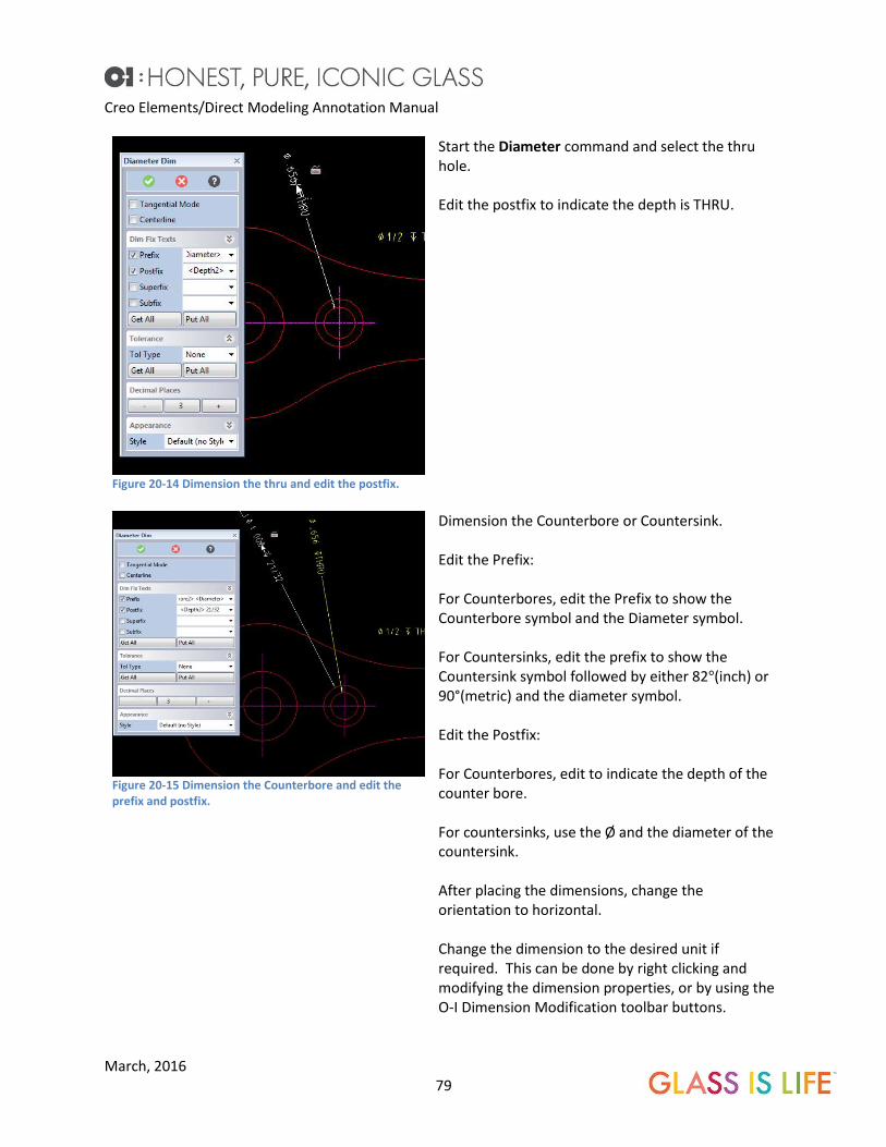
Counterbore and Countersunk holes. Counterbore and Countersunk holes require two steps to dimension. First dimension the thru hole and
the dimension the diameter of the countersink or Counterbore.
Creo Elements/Direct Modeling Annotation Manual
March, 2016 79
Figure 20-14 Dimension the thru and edit the postfix.
Start the Diameter command and select the thru hole. Edit the postfix to indicate the depth is THRU.
Figure 20-15 Dimension the Counterbore and edit the prefix and postfix.
Dimension the Counterbore or Countersink. Edit the Prefix: For Counterbores, edit the Prefix to show the Counterbore symbol and the Diameter symbol. For Countersinks, edit the prefix to show the Countersink symbol followed by either 82°(inch) or 90°(metric) and the diameter symbol. Edit the Postfix: For Counterbores, edit to indicate the depth of the counter bore. For countersinks, use the Ø and the diameter of the countersink. After placing the dimensions, change the orientation to horizontal. Change the dimension to the desired unit if required. This can be done by right clicking and modifying the dimension properties, or by using the O-I Dimension Modification toolbar buttons.

Creo Elements/Direct Modeling Annotation Manual
March, 2016 80
Figure 20-16 Change the orientation to horizontal and position.
Change the orientation of the dimensions to horizontal and position them.
Figure 20-17 Change the leader of the Counterbore to blue.
Change the leader of the Counterbore dimension to blue. Blue is a non-printing color.

Creo Elements/Direct Modeling Annotation Manual
March, 2016 81
Figure 20-18 The blue leader will not plot.
The blue leader will not be plotted.
Figure 20-19 This is how the plot will appear.
The dimension is plotted with only one leader. O-I Plotting defaults do not print blue lines.
21 Tangential Tangential dimensions under the circular dimensioning menu. However, it is basically used for linear
measurements. See Chapter 19.2 TANGENTIAL LINEAR DIMENSIONING.
22 Arc dimensioning. Arc dimensions the length of an arc, or the angle of an arc.

Creo Elements/Direct Modeling Annotation Manual
March, 2016 82
Figure 22-1 The Arc Dim menu.
Start the command. Using the radio buttons choose either to dimension the length of the arc, or the angle of the arc.
Figure 22-2 Arc Length.
For arc Length, select the start point of the arc. Going counter clockwise select the end point. Position the dimension. Note that the linear dimension only works directly on the arc. The linear dimension will not be able to measure missing piece in this view.

Creo Elements/Direct Modeling Annotation Manual
March, 2016 83
Figure 22-3 Arc Angle.
The Angle selection (see FIGURE 22-1) in the Arc Dim can dimension an arc itself, or the missing piece. Select the start point. Going counter clockwise, select the end point of the arc. Place the dimension.
23 Angular Dimensioning. The most difficult thing about angular dimensioning is getting the orientation correct.
Figure 23-1 Start the command and pick the entities.
Start the Angle command. Pick the entities to be dimensioned, the order does not matter.

Creo Elements/Direct Modeling Annotation Manual
March, 2016 84
Figure 23-2 work with the orientation to achieve the desired appearance.
If the angle is not oriented correctly, right click and select the options. In this example the required dimension is 30° between the base and the lip. Clicking on Swap and then Adjacent- gives us this orientation. This process is experimental and it will take some practice to become proficient. Do not get frustrated, eventually the angle dimension will be correctly oriented.
Figure 23-3 This is the correct orientation.
This is the correctly oriented angular dimension.
Figure 23-4 Completed dimension.
Similar to the radius dimensions, switch the orientation to horizontal.
Modifying Dimensions.

Creo Elements/Direct Modeling Annotation Manual
March, 2016 85
Dimension Properties. The user can modify dimension colors and orientation.
Figure 23-5 One of the Many O-I Toolbars available.
The O-I Toolbars are many one click methods of changing the dimension properties. Clicking on these buttons and then on the dimension will quickly change the dimension properties. For example, the AB Vert will change all dimensions clicked on to a vertical orientation.
Figure 23-6 Dimension Properties Menu.
Clicking on the dimension and then clicking Dimension Properties from the Mini Toolbar brings up the Dimension Properties menu. All aspects of the dimension can be changed with this menu including the units, adding second units, the arrow type and color, the text type and color. The Fix Text can also be edited from this menu.
Stagger extension Lines/move dimension text. Overcrowded dimensions are difficult to read. The extension lines can be staggered and text moved to
improve the clarity of the drawing.

Creo Elements/Direct Modeling Annotation Manual
March, 2016 86
Figure 23-7 Stagger command in the Mini Toolbar.
Click on the extension line where the stagger is to start. Click the Stagger button from the Mini Toolbar.
Figure 23-8 Click the second stagger point.
Click the second point on the extension line where the stagger is to end.
Figure 23-9 Click the stagger to point.
Select the point where the stagger is to offset.
Creo Elements/Direct Modeling Annotation Manual
March, 2016 87
Figure 23-10 Completed Stagger command.
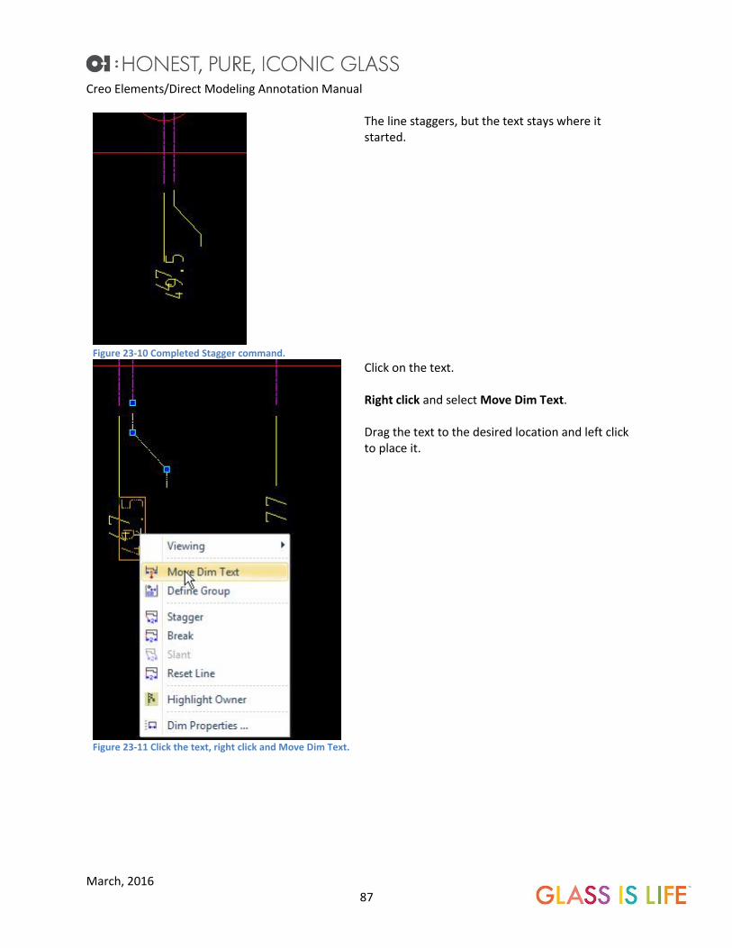
The line staggers, but the text stays where it started.
Figure 23-11 Click the text, right click and Move Dim Text.
Click on the text. Right click and select Move Dim Text. Drag the text to the desired location and left click to place it.

Creo Elements/Direct Modeling Annotation Manual
March, 2016 88
Figure 23-12 Click the new location for the text.
Completed Stagger.
Figure 23-13 Reset the line.
To remove the stagger: Click on the dimension. Select Reset Line from the Mini Toolbar. Drag the text and it will automatically realign with the dimension.
Break Extension Lines. Extensions lines that cross over other extension lines or text confuse a drawing. These extension lines
should be broken and is the proper drafting technique.

Creo Elements/Direct Modeling Annotation Manual
March, 2016 89
Figure 23-14 Overlapping extension lines.
The 35mm and 29mm extension lines cross over other dimensions. This is bad form and these lines should be broken. A single overlapping line can be fixed using the Mini Toolbar. The two overlapping lines can be broken with the Mini Toolbar command, but there is a simpler and better way. This is discussed below.
Figure 23-15 Click the break start point.
A simple break is one that does not have overlapping extension lines. Click the extension line where the break is to begin. Select Break from the Mini Toolbar.
Figure 23-16 Click the break end point.
Select the second point of the break on the extension line.
Figure 23-17 The broken line.
This is the completed break. The other extension line is overlapping. This command would have to be used twice to break two overlapping lines. This is time consuming and difficult. Instead, use the Multi-Break command.
Creo Elements/Direct Modeling Annotation Manual
March, 2016 90
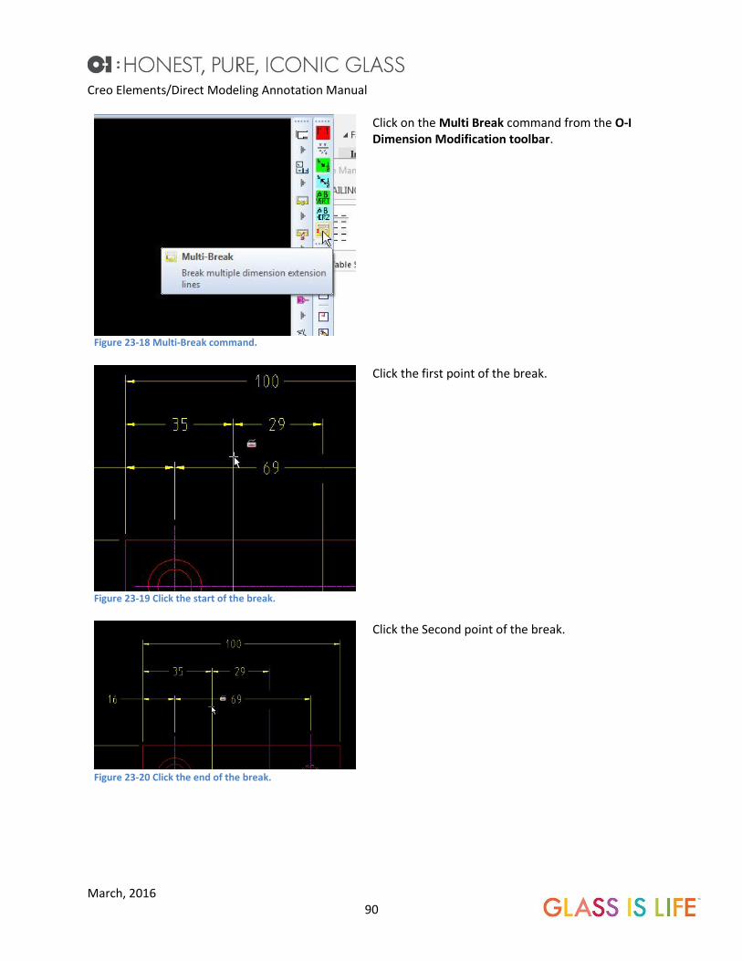
Figure 23-18 Multi-Break command.
Click on the Multi Break command from the O-I Dimension Modification toolbar.
Figure 23-19 Click the start of the break.
Click the first point of the break.
Figure 23-20 Click the end of the break.
Click the Second point of the break.
Creo Elements/Direct Modeling Annotation Manual
March, 2016 91
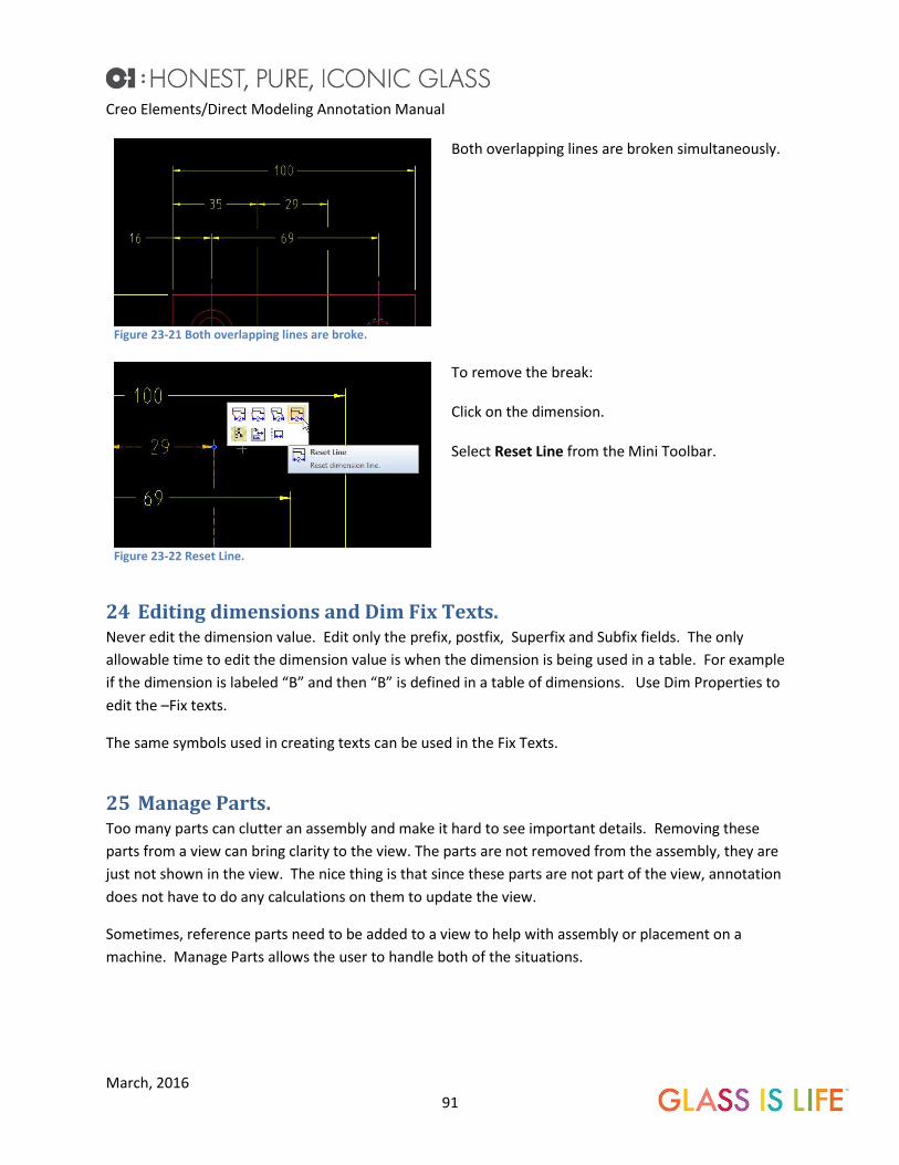
Figure 23-21 Both overlapping lines are broke.
Both overlapping lines are broken simultaneously.
Figure 23-22 Reset Line.
To remove the break: Click on the dimension. Select Reset Line from the Mini Toolbar.
24 Editing dimensions and Dim Fix Texts. Never edit the dimension value. Edit only the prefix, postfix, Superfix and Subfix fields. The only
allowable time to edit the dimension value is when the dimension is being used in a table. For example
if the dimension is labeled “B” and then “B” is defined in a table of dimensions. Use Dim Properties to
edit the –Fix texts.
The same symbols used in creating texts can be used in the Fix Texts.
25 Manage Parts. Too many parts can clutter an assembly and make it hard to see important details. Removing these
parts from a view can bring clarity to the view. The parts are not removed from the assembly, they are
just not shown in the view. The nice thing is that since these parts are not part of the view, annotation
does not have to do any calculations on them to update the view.
Sometimes, reference parts need to be added to a view to help with assembly or placement on a
machine. Manage Parts allows the user to handle both of the situations.

Creo Elements/Direct Modeling Annotation Manual
March, 2016 92
Remove Parts.
Figure 25-1 The bolts and washers on the left side should be removed from the view.
The bolts and the nuts on the left side of this view need to be removed to clarify this view.
Figure 25-2 Click the view and select Manage.
Click on the view. Select Manage from the Mini Toolbar.

Creo Elements/Direct Modeling Annotation Manual
March, 2016 93
Figure 25-3 It is recommended to always click the Expand button.
An auxiliary 3D Viewport opens. The Manage Parts/Workplane menu opens. Expand the entire Dialog box (always do this to show all of the options.) Select Rem Selected (default) Select the part(s) to be removed. Click the Green Checkmark.
Figure 25-4 Update the view.
Update the view.
Add Parts. Manage Parts can also add parts into a view. The parts must be in the assembly, directly under the
assembly, in a subassembly, or in a container. The example below is simplified, adding parts from a
subassembly or container works the same exact way.
Figure 25-5 Add the fasteners back into this view.
The fasteners are to be added back into this view. Click the view. Select Manage from the Mini Toolbar.
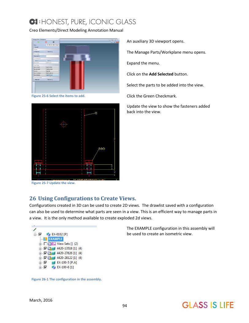
Creo Elements/Direct Modeling Annotation Manual
March, 2016 94
Figure 25-6 Select the items to add.
An auxiliary 3D viewport opens. The Manage Parts/Workplane menu opens. Expand the menu. Click on the Add Selected button. Select the parts to be added into the view. Click the Green Checkmark.
Figure 25-7 Update the view.
Update the view to show the fasteners added back into the view.
26 Using Configurations to Create Views. Configurations created in 3D can be used to create 2D views. The drawlist saved with a configuration
can also be used to determine what parts are seen in a view. This is an efficient way to manage parts in
a view. It is the only method available to create exploded 2d views.
Figure 26-1 The configuration in the assembly.
The EXAMPLE configuration in this assembly will be used to create an isometric view.

Creo Elements/Direct Modeling Annotation Manual
March, 2016 95
Figure 26-2 The configuration applied to the model.
This is the configuration applied to a model.
Figure 26-3 Select the configuration to apply to the view.
Start by Adding a view to the drawing. Select the Configuration to be used from the drop down list.

Creo Elements/Direct Modeling Annotation Manual
March, 2016 96
Figure 26-4 Select how the drawlist affects the view.
Determine how the Drawlist will affect the view. No: The view will show all of the parts in the assembly, even if they are not part of the configuration. Once: Only the parts in the configuration will be shown in the view. However, parts can be added or removed by Managing the view. Always: Only the parts in the configuration will be shown in the view. Parts cannot be added to or removed from the view by Managing the view. Changing the configuration will change the view. To add parts or remove parts from the view, the configuration will have to be modified.
Figure 26-5 Click on direction to create an isometric view.
Click on Direction to create an Isometric view.
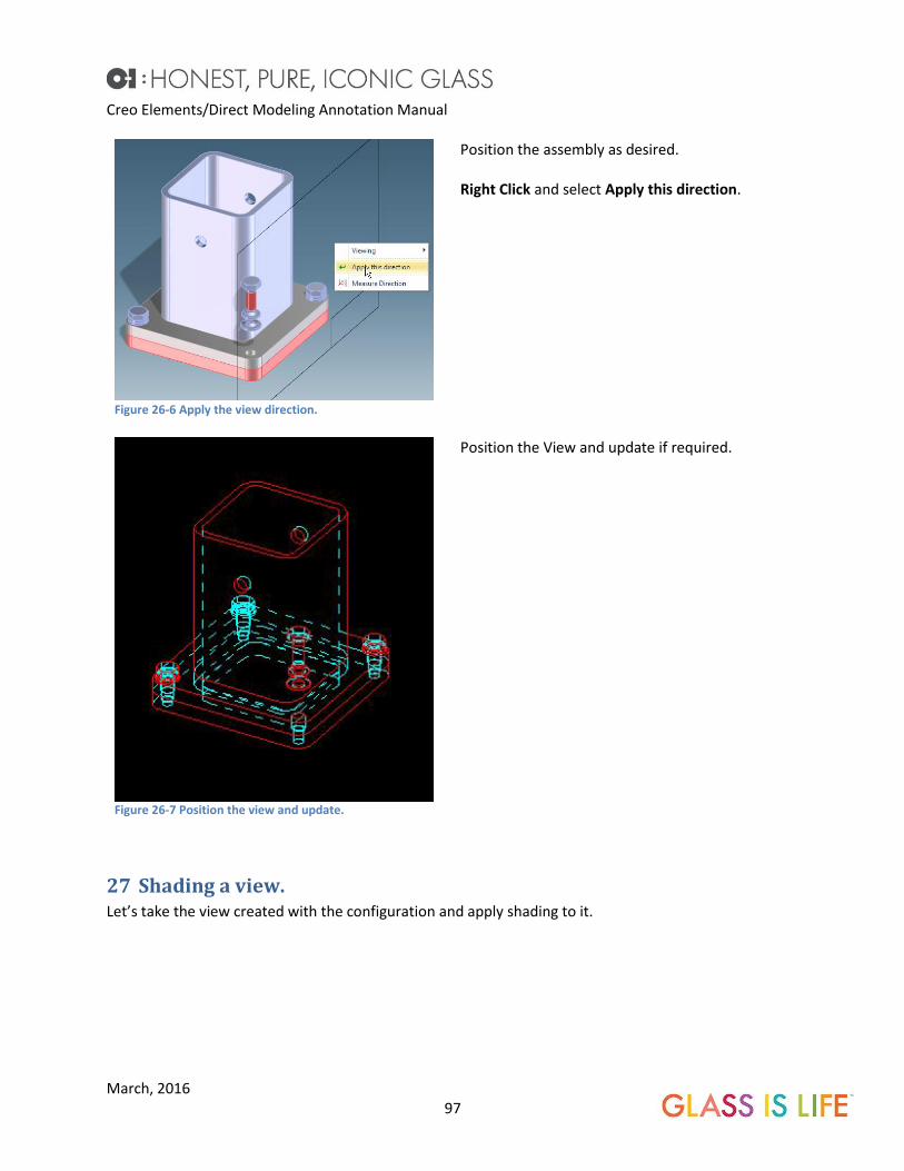
Creo Elements/Direct Modeling Annotation Manual
March, 2016 97
Figure 26-6 Apply the view direction.
Position the assembly as desired. Right Click and select Apply this direction.
Figure 26-7 Position the view and update.
Position the View and update if required.
27 Shading a view. Let’s take the view created with the configuration and apply shading to it.

Creo Elements/Direct Modeling Annotation Manual
March, 2016 98
Figure 27-1 Open the View Properties.
Click on a view and select View Properties from the Mini Toolbar.
Figure 27-2 Select (current) + Shaded.
Select Shaded from the dropdown menu. If the view was originally Graphics, select Graphics + Shaded. If the view was original Classic, select Classic + Shaded.

Creo Elements/Direct Modeling Annotation Manual
March, 2016 99
Figure 27-3 Do not show Hidden, Tangent, Symmetry, or Center lines.
Do not show Hidden lines, Tangent lines, Symmetry Lines or Center lines.
Figure 27-4 Change the Normal line color to Part/WP Colors.
Change the Appearance of normal lines by changing the Color to Part/WP Colors.
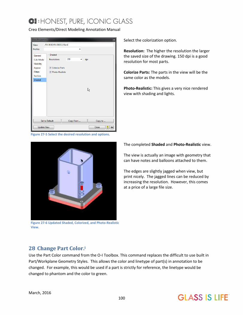
Creo Elements/Direct Modeling Annotation Manual
March, 2016 100
Figure 27-5 Select the desired resolution and options.
Select the colorization option. Resolution: The higher the resolution the larger the saved size of the drawing. 150 dpi is a good resolution for most parts. Colorize Parts: The parts in the view will be the same color as the models. Photo-Realistic: This gives a very nice rendered view with shading and lights.
Figure 27-6 Updated Shaded, Colorized, and Photo-Realistic View.
The completed Shaded and Photo-Realistic view. The view is actually an image with geometry that can have notes and balloons attached to them. The edges are slightly jagged when view, but print nicely. The jagged lines can be reduced by increasing the resolution. However, this comes at a price of a large file size.
28 Change Part Color.i Use the Part Color command from the O-I Toolbox. This command replaces the difficult to use built in
Part/Workplane Geometry Styles. This allows the color and linetype of part(s) in annotation to be
changed. For example, this would be used if a part is strictly for reference, the linetype would be
changed to phantom and the color to green.

Creo Elements/Direct Modeling Annotation Manual
March, 2016 101
Figure 28-1 assembly with reference parts.
This assembly has several parts that are for reference. The reference parts are not part of the bill of material but are important in this view to show how the assembly mates to the reference parts. O-I standards dictate that these reference parts should be phantom. The line color should be green to plot with the proper lineweight.
Figure 28-2 Select the parts that will be revised in annotation.
Start the Part Color command from the O-I Toolbox Tab on the Ribbon Menu. To show the 3D model, click the 3D-View radio button. Notice that the Select automatically has the Recursive radio button selected. With this selected, clicking a single part will automatically select the entire parent assembly. To select single parts un-check the Recursive radio button. Select the parts that will be revised in annotation. Click Start on the select list to make a list of parts. Click the center mouse button when complete.
Figure 28-3 Select the view to revise.
Select the view(s) to be revised.

Creo Elements/Direct Modeling Annotation Manual
March, 2016 102
Figure 28-4 Select the color
Select the color of the revised parts. Notice that the Auto-update radio button is checked. This will force an update of the view when the Green Checkmark is clicked.
Figure 28-5 Select the linetype.
Select the linetype.
Figure 28-6 Click The Green Checkmark.
Click the Green Checkmark.
29 Improving Update Performance. Large drawings can take a very long time to update the views. This chapter gives tips and trick on
improving the time it takes for these view to update.
Remove Invisible. Annotation will calculate each part in an assembly in order to update a view, even if those parts are not
visible in a view. The update time for a view can be improved if these invisible parts are removed.

Creo Elements/Direct Modeling Annotation Manual
March, 2016 103
Figure 29-1 Remove Invisible parts.
Manage the parts in a view, expand the Manage Parts menu and click the Rem Invisible button. Click the Green Checkmark. SEE CHAPTER 24
EDITING DIMENSIONS and Dim Fix Texts. Never edit the dimension value. Edit only the prefix, postfix, Superfix and Subfix fields. The only allowable time to edit the dimension value is when the dimension is being used in a table. For example if the dimension is labeled “B” and then “B” is defined in a table of dimensions. Use Dim Properties to edit the –Fix texts. The same symbols used in creating texts can be used in the Fix Texts. Manage Parts.
The second option is to click the Rem. Inv. Parts button in the O-I Toolbox tab on the Ribbon Menu and
click the view(s).
Figure 29-2 O-I Toolbox button
Calc Mode. Calc Mode settings play a large role in the speed of an update. Making sure that view profiles is checked
when creating a view. It will automatically pick the optimal Calc Mode. These settings can always be
over-ridden by the user.
Large assemblies are those that have over 100 parts, or parts with complex splines.
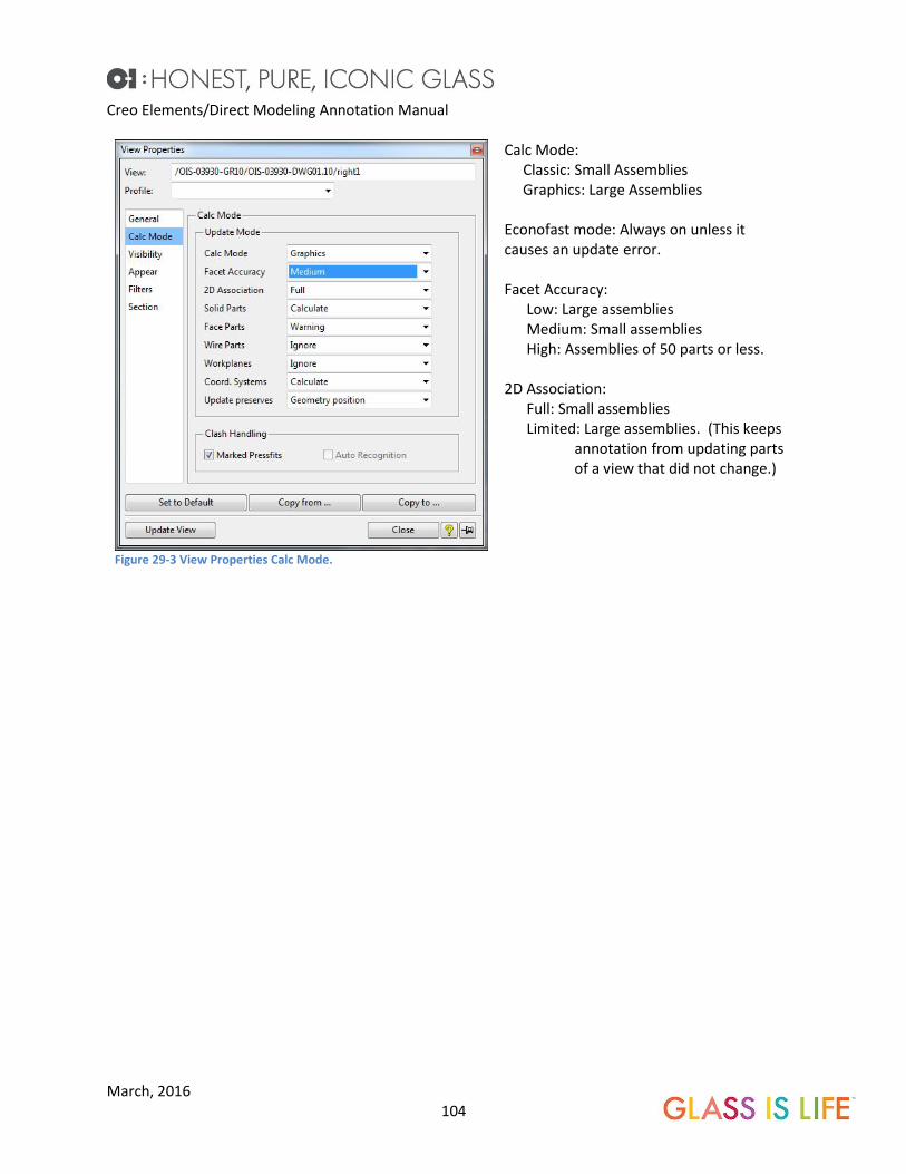
Creo Elements/Direct Modeling Annotation Manual
March, 2016 104
Figure 29-3 View Properties Calc Mode.
Calc Mode: Classic: Small Assemblies Graphics: Large Assemblies Econofast mode: Always on unless it causes an update error. Facet Accuracy: Low: Large assemblies Medium: Small assemblies High: Assemblies of 50 parts or less. 2D Association: Full: Small assemblies Limited: Large assemblies. (This keeps annotation from updating parts of a view that did not change.)

Creo Elements/Direct Modeling Annotation Manual
March, 2016 105
30 Appendix.
Fixing the View Reference Points. Sometimes views are created with the reference point of the view off in space. This make the views
very difficult to line up. There is a tool in the Toolbox Dropdown Menu to fix this.
Figure 30-1 The view reference point (cross hairs and purple dot) are not on the view.
The top views reference point is not located in the center of the view. The reference point is the purple dot on the green crosshairs This makes this view difficult to line up with other views. There is a tool to fix this.
Figure 30-2 Toolbox Dropdown Menu.
Open the Toolbox Dropdown Menu.
Figure 30-3 Start the Set View Ref Pnt. command.
Start the Set View Ref Pnt command.

Creo Elements/Direct Modeling Annotation Manual
March, 2016 106
Figure 30-4 Select the view to fix.
Select a view to fix.
Figure 30-5 Select a point on the view.
Select a new reference point. Pick a point that can be easily found on the 3D geometry. For this example, the center of the boss was selected, since this is an easy point to pick on the drawing and the model.
Figure 30-6 Select the same point on the 3D model.
An Auxiliary 3D viewport opens. Select the reference point on the 3D model. Click the Green Checkmark.
Figure 30-7 The View reference point is fixed.
The reference point for the view is now corrected for this view. These steps must be repeated for each view on the drawing.

Creo Elements/Direct Modeling Annotation Manual
March, 2016 107
31 Revision History. 2-24-2016 approved for proof read.
3-10-2016 ready for final proof read.
3-23-2016 Released Version 1.0.
32 Credits V1. Written by Thomas R. Kirkman, Proofread and edited by Charlie Obee, Susan Taber and Josh
Przbylski.
33 Endnotes.
i This section is copied from the Creo Elements Direct Modeling O-I Toolbox commands v6.0