Creature Generation using Genetic Algorithms and...
62
Creature Generation using Genetic Algorithms and Auto-Rigging Jon Hudson Master of Science, Computer Animation and Visual Effects NCCA August, 2013
Transcript of Creature Generation using Genetic Algorithms and...

Creature Generation usingGenetic Algorithms and
Auto-Rigging
Jon Hudson
Master of Science,
Computer Animation and Visual Effects
NCCA
August, 2013

Contents
Table of contents . . . . . . . . . . . . . . . . . . . . . . . . . . . . . . . i
Abstract . . . . . . . . . . . . . . . . . . . . . . . . . . . . . . . . . . . . v
Acknowledgements . . . . . . . . . . . . . . . . . . . . . . . . . . . . . . vi
1 Introduction 1
1.1 Report Structure: . . . . . . . . . . . . . . . . . . . . . . . . . . . . 2
2 Previous Work 4
3 Technical Background 6
3.1 Genetic Algorithms . . . . . . . . . . . . . . . . . . . . . . . . . . . 6
3.2 Houdini Object Model . . . . . . . . . . . . . . . . . . . . . . . . . 7
4 Design and Development: 8
4.1 Creator Generator . . . . . . . . . . . . . . . . . . . . . . . . . . . 9
4.1.1 Creature Generator Tool: . . . . . . . . . . . . . . . . . . . . 9
4.1.2 Legs: . . . . . . . . . . . . . . . . . . . . . . . . . . . . . . . 12
4.1.3 Body: . . . . . . . . . . . . . . . . . . . . . . . . . . . . . . 13
4.1.4 Arms: . . . . . . . . . . . . . . . . . . . . . . . . . . . . . . 13
4.1.5 Neck and Tail: . . . . . . . . . . . . . . . . . . . . . . . . . . 15
4.1.6 Wings: . . . . . . . . . . . . . . . . . . . . . . . . . . . . . . 15
4.2 Creature Builder: . . . . . . . . . . . . . . . . . . . . . . . . . . . . 16
4.3 Creature Rigger: . . . . . . . . . . . . . . . . . . . . . . . . . . . . 17
4.3.1 Spine/Neck/Tail: . . . . . . . . . . . . . . . . . . . . . . . . 19
4.3.2 Arms: . . . . . . . . . . . . . . . . . . . . . . . . . . . . . . 20
4.3.3 Legs: . . . . . . . . . . . . . . . . . . . . . . . . . . . . . . . 21
4.3.4 Wings: . . . . . . . . . . . . . . . . . . . . . . . . . . . . . . 22
4.3.5 Bone Capture Buckets: . . . . . . . . . . . . . . . . . . . . . 23
i

4.3.6 Attaching the Rig to the Creature: . . . . . . . . . . . . . . 24
4.3.7 Building a proper Creature Mesh: . . . . . . . . . . . . . . . 24
5 Genetic Algorithm 26
5.1 Crossover: . . . . . . . . . . . . . . . . . . . . . . . . . . . . . . . . 26
5.2 Mutation: . . . . . . . . . . . . . . . . . . . . . . . . . . . . . . . . 27
5.3 Use for Creature Variation: . . . . . . . . . . . . . . . . . . . . . . . 27
6 GUIs and Tool Controls 29
6.1 GUI Threading Bugs: . . . . . . . . . . . . . . . . . . . . . . . . . . 31
6.2 Creature Generator GUI: . . . . . . . . . . . . . . . . . . . . . . . . 31
6.2.1 Functions: . . . . . . . . . . . . . . . . . . . . . . . . . . . . 31
6.2.2 Creating Digital Assets: . . . . . . . . . . . . . . . . . . . . 35
6.2.3 Creature Generator vs Creature Designer: . . . . . . . . . . 36
6.3 Genetic Algorithm GUI: . . . . . . . . . . . . . . . . . . . . . . . . 36
6.4 Procedural Creature Rig Control GUI: . . . . . . . . . . . . . . . . 38
7 Examples: 47
8 Conclusion 51
8.1 Future Work: . . . . . . . . . . . . . . . . . . . . . . . . . . . . . . 52
References 52
ii

List of Figures
4.1 Main and subsections of Wings . . . . . . . . . . . . . . . . . . . . 16
4.2 Spine, Neck and Tail Controls . . . . . . . . . . . . . . . . . . . . . 20
4.3 Arm and Finger Controls . . . . . . . . . . . . . . . . . . . . . . . . 21
4.4 Leg Controls . . . . . . . . . . . . . . . . . . . . . . . . . . . . . . . 22
4.5 Wing Controls . . . . . . . . . . . . . . . . . . . . . . . . . . . . . . 23
4.6 Proxy Geometry and Mesh made in Maya for a creature . . . . . . 25
5.1 A Single Parent Creature . . . . . . . . . . . . . . . . . . . . . . . . 28
5.2 Children generated for the single Parent seen in Figure 5.1 . . . . . 28
6.1 Creature Generator GUI Main Page . . . . . . . . . . . . . . . . . . 32
6.2 Creature Generator GUI Second and Third Pages . . . . . . . . . . 33
6.3 Creature Generator GUI Final Page . . . . . . . . . . . . . . . . . . 34
6.4 Genetic Algorithm for Creature Creature GUI . . . . . . . . . . . . 36
6.5 Parent Creatures . . . . . . . . . . . . . . . . . . . . . . . . . . . . 37
6.6 Child Creatures generated from Parent Creatures in Figure 6.5 . . . 38
6.7 Creature GUI - Main Tab . . . . . . . . . . . . . . . . . . . . . . . 41
6.8 Creature GUI - Arm Tab . . . . . . . . . . . . . . . . . . . . . . . . 42
6.9 Creature GUI - Leg Tab . . . . . . . . . . . . . . . . . . . . . . . . 43
6.10 Creature GUI - Wing Tab . . . . . . . . . . . . . . . . . . . . . . . 44
6.11 Creature GUI - Neck and Spine Tabs . . . . . . . . . . . . . . . . . 45
6.12 Creature GUI - Tail Tab . . . . . . . . . . . . . . . . . . . . . . . . 46
7.1 A Generation of Creatures . . . . . . . . . . . . . . . . . . . . . . . 47
7.2 Four Creatures seen generated in project videos . . . . . . . . . . . 48
7.3 Parent (Left) generated as child of Figure 7.2 and its Child (right)
generated via Mutation of Parent alone . . . . . . . . . . . . . . . . 49
7.4 Bone, Proxy Geometry and Mesh of a Creature Arm . . . . . . . . 50
iii

List of Algorithms
1 Main Algorithm . . . . . . . . . . . . . . . . . . . . . . . . . . . . . 11
2 Algorithm for adding changes to the geometry to the creatures save
file . . . . . . . . . . . . . . . . . . . . . . . . . . . . . . . . . . . . 12
3 Leg Algorithm . . . . . . . . . . . . . . . . . . . . . . . . . . . . . . 13
4 Crustacean/Arachnid Leg Algorithm . . . . . . . . . . . . . . . . . 14
5 Body Algorithm . . . . . . . . . . . . . . . . . . . . . . . . . . . . . 14
6 Arm Algorithm . . . . . . . . . . . . . . . . . . . . . . . . . . . . . 15
7 Neck and Tail Algorithms . . . . . . . . . . . . . . . . . . . . . . . 15
8 Wing Algorithm . . . . . . . . . . . . . . . . . . . . . . . . . . . . . 16
9 Procedural Creature GUI Algorithm . . . . . . . . . . . . . . . . . 40
iv

Abstract
This report covers the design and development of tools for Creature Generation
and Development, considering a novel solution towards creature generation and
auto rigging.
Three tools were developed, the first of which will generate a series of creatures
based on variables the user provides and provides functionality to save and re-load
designs as well as generating a bone rig and appropriate controls for any given
creature. The second tool employs a Genetic Algorithm to breed creatures to create
new generations and can be used to generate variations on a single design, creating
a species. The final tool is a Procedural GUI system, written in wxPython and
utilising wxGlade, that will generate a bespoke Control GUI for any given creature
providing the user a GUI based control system alongside the visual controls that
are generated with the rig.
The project represents a novel pipeline for fast creature development, bypass-
ing concept drawings and potentially providing designs the user would never have
previously considered, whilst also allowing automatic rigging solutions to any gen-
erated design. There are limitations to the extent of parts designed and number
created, however the tools created are an excellent platform for future development
in automated creature design and rigging.
v

Acknowledgements
The author would like to thank Jon Macey, Phil Spicer and the 2013 MSc class.
vi

Chapter 1
Introduction
The purpose of the Masters Project is to perform a substantial piece of work in
the field of Animation and Visual Effects. There were a number of areas of interest
considered that could have resulted in interesting and useful projects; from among
them it was decided to create a tool written in Houdini that would leverage the
power of the Houdini Object Model (HOM) and its interface with the programming
language Python to procedurally generate systems of nodes to achieve a given goal.
This would provide a lot of knowledge of scripting in Python, and the use of the
HOM to design and create tools within Houdini, both being excellent transferable
skills.
The project decided upon was to build a suite of tools which would act as a
Creature Generator program. The hope would be to design and build a set of tools
in Houdini that would allow a user to generate a set of creatures based on some
information provided by the user, the features and sizes of each being random
within user set limits. The tools would then employ Genetic Algorithms to further
allow the user to select which designs to take forward and use as the parents of the
next generation until they arrived at a design (or designs) they were happy with.
The general idea was that such a program would be of use to anyone who
wanted to quickly create a series of simple creatures that could be used for film,
TV, games and art applications. The generated creatures would not themselves be
of high enough fidelity to use directly, but could be used as proxy geometry, which
could be exported and around which a proper mesh could be designed. The utility
1

of the program would be in providing the user quickly with a large array of designs,
many of which they may have never considered themselves. This is not the usual
design processes for a creative task such as creature development, which would
ordinarily begin with concept designs drawn up and re-designed before actual 3D
creature modelling and later rigging takes place.
Out of this concept an additional idea quickly became apparent. In order to
generate a creature, composed of different parts, the program must have a lot of
information about the relative sizes and positions of all these components and if it
has this information, due to the possibility of using the HOM to generate Houdinis
bones and kinematic solvers, it might be possible to not only generate a creature,
but to create a basic bone rig for it as well.
Successfully bringing these two functions together would mean that a user could
quickly generate a series of creature designs, and evolve them through successive
generations to arrive at designs that they wanted to use. They could then im-
mediately generate a basic rig for a given creature with which they could begin
animating right away - with the generated creature acting as a proxy character -
whilst the proxy geometry was being used as the blueprint for creating a proper
creature mesh elsewhere. That completed mesh could then be brought back into
Houdini and tied to the animation that had already been done (additional weight
painting would still be required to achieve the users desired final capture of the
rig). This system, whilst somewhat unconventional, could save time for users and
be used as both a creativity tool as well as a productivity tool.
1.1 Report Structure:
The report is split into the following sections:
Chapter 1 - Introduction
Chapter 2 Previous works
Chapter 3 Technical Background
Chapter 4 Design and implementation
Chapter 5 Examples
2

Chapter 6 Conclusion
Chapter 8 - References
3

Chapter 2
Previous Work
The main influence of forming the initial idea for the project was Venter and
Hardy’s paper Generating plants with gene expression programming (Venter &
Hardy 2007) which explores evolving L-Systems (for plant design) with a Genetic
Algorithm, based on users aesthetic preferences. A Genetic Algorithm is a system
that takes two individual items, selected for their fitness for a given purpose, and
breeds them to produce offspring; this process will be further detailed in the next
section of this report. This use of a Genetic Algorithm whose generations are
influenced by the decisions of a user is a process often referred to as Aesthetic
Evolutionary Design (AED).
Bentley described in his paper Aspects of Evolutionary Design by Computers
(Bentley 1999) the four main types of Evolutionary Design as employed by comput-
ers, and how their overlapping has led to four new areas, one of which is Aesthetic
Evolutionary Design, whereby a design is evolved purely on its aesthetics rather
than anything else.
Rowland presented an excellent example of artist use of Genetic Algorithms in
a system (Rowland & Biocca 2000) where a users aesthetic choices are used to
breed new populations, in this case, virtual sculptures.
There are two interesting papers on generating simple characters, to be refined
purely by the by the eye and aesthetic taste of the user. Ogura and Hagiwara
presented a paper (Ogura & Hagiwara 2013) that used a Genetic Algorithm to
generate and refine 3D faces whilst Ando and Hagiwara presented a paper (Ando
4
& Hagiwara 2009) dealing with entire characters. These systems employed an
interesting function whereby they attempted to extract rules based on the user
selection, in order to try and present solutions that the user is more likely to find
aesthetically pleasing. This is a fascinating augmentation to the procedure and one
that could be of interest in developing further the tools described by this report.
There are two prior works that are the closest in terms of prior art to the
specifics of the program developed during this project. The first was a generalised
Genetic Algorithm called Metavolve (Lewis et al. 2001), designed to be used in
Houdini as a Genetic Algorithm that could be used for a number of purposes. One
of the potential purposes that was shown as a work in progress was the evolution
of humanoid body shapes, which is similar in principle to this project, however this
project seeks to generate creatures with multiple limbs and form factors beyond
humanoid.
The prior work that most resembles this project was the work of Yamamoto,
Maki and Shirai in their project ’Skeleton-based diverse creature design tool for
mass production’ (Yamamoto et al. 2011), which was a tool written in Python and
designed for Maya, explicitly aimed at creating a tool to quickly create many useful
designs. Their program would allow a user to pick bone chains for sections of a
creature based on body part templates and join them together as well as move and
otherwise alter them. This would result in a controllable skeleton around which
a creature could then be designed. They describe the results of one of their (at
the time) most recent tests as ”an artist who can create tarot [sic] 22 creatures in
20 days in sketch based workflow was able to create 10 base creatures in 3 days
with skeletal structures and sketches”. This statement suggests that a workflow
based around creating a skeleton and then altering it to produce designs was highly
advantageous in terms of time.
It is this observation that is the the backbone of the idea behind the tools
developed in this project, that of creating tools that can speed up the work of artists
and designers. The hope of this project is to result in a set of tools that allows
rapid creature creation, alteration by genetic algorithm and automatic rigging to
provide a robust pipeline to enhance both the creativity and speed of artists and
designers.
5

Chapter 3
Technical Background
3.1 Genetic Algorithms
The following is a brief explanation of Genetic Algorithms (GAs), which are em-
ployed by this program. GAs are a form of Evolutionary Computing, whereby
a program attempts to optimize a given problem. GAs were first developed by
John Holland in the 1970’s and published in his book ’Adaptation in natural and
artificial systems’ (Holland 1992).
GAs can be employed in any area where a population of individuals (or pheno-
types) can be represented by sequences of genes that the genetic operations can
be performed on. These individuals can be anything, from pictures to coded com-
puter programs, as long as an appropriate representation of them can be made for
the algorithm to work upon. The representation is as a series of ’genes’ relating to
aspects of the ’individual’, these are often coded in binary, but other appropriate
representations are possible, such as arrays or the use of Python dictionaries as
used in this project. There are two main operations that are performed by a GA
on the genes of its ’individuals’, Crossover and Mutation, but dependant on the
GA, other operations may also be used such as those used by Akbari and Ziarati,
migration and re-grouping (Akbari & Ziarati 2011).
The specifics of GAs depend on the type of problem and the sort of entities
that it is operating on, but all GAs have the same function, to narrow down the
search space (containing all possible solutions, regardless of their quality) to find
6

the optimal solution. To do this they generate an initial population of ’individuals’
(potential solutions to the problem) and select parents for a new generation from
these, based on their fitness to a given task or goal. For each new entity that needs
to be generated, a pair of parents is randomly selected from the parents group.
One parent is taken as the base code and then has half the genes of the second
parent (chosen at random) swapped with its own comparative genes.
Following this procedure a new entity has been created which may then undergo
mutation if desired. Mutation can be as simple as swapping the value of a single
digit in a genome comprised from a binary representation, to more involved pro-
cesses such as randomly generating a number for every gene and if that number is
below a set Mutation Rate (or threshold) then causing that gene to mutate in a
way specific to that program.
Fitness is usually calculated by the algorithm based on the attributes of an
entity and designing this fitness function can be a very difficult job, depending on
the problem area being faced. But the complexity is variable depending on what
the entities are and their goal, for instance in Sims seminal paper Evolving Virtual
Creatures (Sims 1994), which generated moving creatures from primitive blocks,
fitness for jumping creatures was calculated by the highest point the creature
reached during a set time period.
Fitness is considered differently however in the tool presented in this report.
For the purposes of the GA employed in the tools for this project, the fitness
is actually decided by the user, based on creature appearance alone, making the
fitness function the users own aesthetic eye.
3.2 Houdini Object Model
The Houdini Object Model (HOM) is used extensively in this project. It is an
Application Programming Interface (API), that allows the user to interact with
the component nodes of Houdini to poll information from them, perform operations
on them etc, through use of the Python programming language.
7

Chapter 4
Design and Development:
As it was decided to write the program as Python and HOM script, the process
of writing the program for the project was split up into a number of Houdini
shelf tools to perform different tasks and test small bits of code separately before
integration. The original iteration of the program as presented at the mid-term
critical presentations did not have a GUI and was implemented as code only. This
was done for the sake of speed since the program was still expected to change
and evolve further during development and so it was decided that creating a GUI
should be done later in the timeline when the project features were more firmly
fixed.
The initial two tools developed were the main Creature Generator and Genetic
Algorithm tools, which will now be further detailed. Following on from there is
an explanation of the GUIs designed to interface with the code and then the final
tool, the procedural Control GUI for the creatures.
All these tools are available in the folder title Utilities accompanying this report.
In order to run these tool successfully, the main folder Creature Generator should
be placed in a users home directory, as the code works relative to that folder
and the folders it contains. The code for each of the four tools should be placed
into separate shelf tools in Houdini, the first three CreatureGen, GA, GUI were
developed for this project and Fix contains a sample program by SideFX (the
makers of Houdini), that whilst unrelated to this project, is present due to a bug
with running the GUIs successfully that is detailed later in this report.
8

Early attempts at splitting various algorithms off into separate modules to then
be imported to Houdini again by simpler main tools, were failures. This seemed to
be due to an issue where Houdini wouldnt recognise the hou notation (necessary
for node calls in HOM) if it was being imported from another file. Due to this,
the tools are rather long, dense sequences of code; in the future it would aid the
readability of the code correct to this bug and to split up the code across multiple
files which might also reduce the code size due to shared algorithms or sections
of algorithms appearing in the different tools. At the end of this project it was
realised that this most likely had a simple fix that had not been considered earlier;
in that it might be fixed by importing the ’hou’ module at the start of every
external module, however time did not remain to attempt this solution. It would
be one of the first fixes in an update to the project.
It should be noted that the program was not written to be specifically made
of high integrity or highly efficient code, but was designed to prove a potentially
novel pipeline and the general concept, with the expectation that future iterations
of the program would improve and optimise the code design and structure.
4.1 Creator Generator
The Creature Generator comprises three main parts, the actual Creature Generator
itself, a Creature Builder and the Creature Rigger.
4.1.1 Creature Generator Tool:
The function of the Creature Generator is to take a number of user provided vari-
ables, which are maximums and minimums for both numbers of possible component
parts and their sizes as well as the actual number of creatures that the user would
like to generate. There are some limitations on this initial system for the number
of component parts, in that only one or two pairs of legs and wings are supported.
The reason for the limitation was in order to reduce the complexity to a man-
ageable level, the focus of the project on delivering a cohesive design, rather than
attempting a fully comprehensive system and failing to deliver anything of note.
9

This system however proves the capability of these tools as part of a pipeline and
a future iteration of the programs could remove these limits by extending and aug-
menting the current algorithms. The following sections present the algorithms as
they are currently coded and where applicable, suggestions for appropriate future
algorithms that if implemented would extend the capability of the system.
In order for the generated creatures to be able to work with the Genetic Al-
gorithm tool, all sizes, rotations and positions of pieces are stored in a series of
Python dictionaries (referred to henceforth as the creature’s ’genome’) which are
saved to file via Pythons pickle command at the end of each creatures generation.
The information stored in these is enough to recreate the model of the creature
and to also generate the information necessary to auto-rig it using the rigging tool
designed in this project.
The main algorithm randomly chooses between its provided variables to decide
on what parts the creature being generated will be made from and then it randomly
selects the size of each component based again on the user input. In theory the
user can generate large numbers of creatures, but the design is optimised as a 5 x 5
grid, so 25 creatures is suggested per generation. The general algorithm is detailed
in Algorithm 1.
For the purposes of this program, all creatures are considered to be symmetrical;
the algorithms generate the left side limbs and mirror their parameters to the right
side pieces appropriately. The genome for each creature still consists of both left
and right side pieces, even though their genes are the same, so the program could be
extended to deal with asymmetric individuals, however due to breeding the designs
via the Genetic Algorithm program, asymmetric designs could quickly produce
poor and undesirable aesthetics; however this could be an interesting subject for
future research.
An algorithm could be written to allow a user to alter the proxy geometry
and then save the changes to file, this may allow the rigging program to then
rig the resultant creature and if the appropriate naming conventions were used as
presented throughout the code, could allow additional parts to be added. This
has not been implemented due to time constraints; however Algorithm 2 presents
what would be an appropriate algorithm to run after changes have been made.
10

Algorithm 1 Main Algorithm
for each creature to be generated doChoose random number of legs, arms, sections in arms, fingers, sections in fingers, wings,
main sections in wings, subsections in wings, neck segments and tail segments within set limitsChoose random sizes for head, ears and muzzle sectionsfor every section in the body do
Choose random size for each segmentend forfor each segment in Neck do
Choose random size for segmentend forfor each segment in Tail do
Choose random size for segmentend forfor each Arm do
for each Arm segment doChoose random size for segmentif multiple sets of arms present then
Angle arm appropriatelyend if
end forfor each Finger do
for each Finger segment doChoose random size for segmentif multiple finger then
Angle fingers appropriatelyend if
end forend for
end forfor each Leg do
Choose Leg style:if Biped style then
Create two segments with random sizesend ifif Quadruped style then
Create four segments with random sizes and appropriate rotationsend if
end forfor each Wing do
for each Main Wing segment doChoose random size and angle for segmentfor each Wing sub segment do
for each Wing sub segment doChoose random size angle for all segmentChose random size for segment
end forend for
end forend for
end for
11

Algorithm 2 Algorithm for adding changes to the geometry to the creatures savefile
for each node in creature geometry network doCalculate which entry in the genome corresponds to this nodeif match found then
For each position value:end ifif different then
Update genomeend iffor each rotation value do
if different thenUpdate genome
end ifif no match found then
Add new entry to genomeend if
end for
end for
Specifics of the algorithms used for each of the part types are detailed in the
following sections. Each algorithm determines the parts position in world space,
based on the positions of other relevant body parts and segments of itself and also
adds this position information into the dictionary holding the genome information
for the creature. Once all position information has been calculated, the main
geometry node is collapsed inside of a subnet the reason for this was the hope of
being able to later convert the creature into a Digital Asset, an operation which
must be applied to a subnet.
4.1.2 Legs:
There are two leg types available for the program to employ. A simple Biped style,
which is made from two segments like the shin and thigh of a human leg and a
Quadruped style, based on a generalised animal leg model with four segments. The
generalised animal the design is based on is taken from the book ’Animal Anatomy
For Artists - The Elements of Form’ (Goldfinger 2004), where the leg comprises
Toes, Hind Foot, Lower Leg and Thigh. The algorithm to achieve these Leg types
is presented in Algorithm 3.
The leg segments will later be moved along the X-axis so that they fall at the
sides of body.
12

Algorithm 3 Leg Algorithm
for each Leg doif Leg is Biped style then
Place first segment so that its base is at 0 Y in world spaceCalculate position of top of segmentfor each additional segment do
Place base of next segment at position of top of prior segmentCalculate position of top of segment
end forend ifif Leg is Quadruped style then
Place first segment so that its base is at 0 Y in world spaceCalculate position of top of segmentfor each additional segment do
Place base of next segment at position of top of prior segmentCalculate position of top of segment
end forend if
end for
A future extension to the project would be to allow additional segments to be
added by the program into these leg types. Another extension would be to add
further leg types, the most obvious of which would be crustacean/arachnid style
legs. Such a leg type could be considered as made of two general sections, the
first being a number of segments coming up from the ground, the second being a
number of segments descending from the tip of the first section and meeting the
body at the lowest point of the second section. The general algorithm to achieve
this is shown in Algorithm 4.
4.1.3 Body:
The body is made up of 3 sections, each made up of three segments, based on a
generalised body model of upper, mid and lower torso. The algorithm for this is
detailed in Algorithm 5.
4.1.4 Arms:
The program can generate arms made up of any number of segments, at the end
of which it can also place any number of fingers, also made up of any number
of segments. The code currently restricts the models to having the same number
13

Algorithm 4 Crustacean/Arachnid Leg Algorithm
for each Leg doif Leg is Arachnid style then
for first section doPlace first segment so that its base is at 0 Y in world spaceCalculate position of top of segmentfor each additional segment do
Place base of next segment at position of top of prior segmentCalculate position of top of segment
end forend forfor second section do
Place first segment so that its top is at the top of the first sectionCalculate position of bottom of segmentfor each additional segment do
Place top of next segment at position of base of prior segmentCalculate position of base of segment
end forend for
end if
end for
Algorithm 5 Body Algorithm
Position first central segment at the top of the leg segmentPosition side segments to either side of the central segmentfor each additional central segment do
Place immediately above the highest point of the preceding section (either the top of thecentral or side segments, whichever is higher)
Position side segments to either side of the central segmentif creature has more than one pair of legs then
Shift this row of segments forwardend ifif central segment is the final segment and creature has more than one pair of legs then
Adjust height of final row of segments to be at top of the front pair of legsend iffor each Leg do
Shift segments to be at the extents of the relevant side sections of the creatureend for
end for
14

of fingers on each hand, but this could be changed to allow each hand to have a
different number of fingers and segments. The general algorithm for the arms is
shown in Algorithm 6.
Algorithm 6 Arm Algorithm
for each Arm doPlace start of first segment at edge of bodyCalculate position of end of segmentfor each additional segment in Arm do
Place start at position of end of previous segmentCalculate position of end of segment
end forfor each Finger do
Place start of first segment at end of arm segmentsCalculate position of end of segmentfor each additional segment in Finger do
Place start at position of end of previous segmentCalculate position of end of segment
end forend for
end for
4.1.5 Neck and Tail:
The neck and tail can be made up of multiple segments; however no tail is required
for a given creature, but the neck must be at least one segment in size. The
algorithm for the Neck and Tail sections can be seen in Figure 7.
Algorithm 7 Neck and Tail Algorithms
Place first Neck segment at top of bodyfor each additional Neck segment do
Place above previous segmentPlace first Tail segment behind the base of the bodyfor each additional Tail segment do
Place below and behind previous segmentend for
end for
4.1.6 Wings:
Wings are divided into two sets of segments, the main segments which can be
considered the top edge of the wing and the subsections which branch off of the
15

main section, as shown in Figure 4.1.
Figure 4.1: Main and subsections of Wings
The algorithm decides the sizes of each segment in each part of the wing and
can be seen in Algorithm 8.
Algorithm 8 Wing Algorithm
for each Wing doPlace start of first segment at a random distance behind centre of spineCalculate position of end of segmentfor each additional Main Wing segment do
Place start at position of end of previous segmentCalculate position of end of segment
end forfor each Wing sub-segment do
Place start of first segment at end of a Main Wing segmentCalculate position of end of segmentfor each additional segment in Wing sub-segment do
Place start at position of end of previous segmentCalculate position of end of segment
end forend for
end for
4.2 Creature Builder:
This section of the program reads the genes of a creature and then builds and
connects all the relevant Houdini nodes in order to visualise it. The program
begins by creating a single surface Geo node and deletes the File SOP it contains.
All the creatures geometry will then be placed inside of this node.
16

Since the positions of every part of the creature have already been calculated
during the generation process, the code to visualise the parts is very simple. Each
element of the creature is represented by either a primitive sphere or a tube, which
can be easily generated in Houdini via HOM script. Depending on how the part is
to be visualised, the algorithm will select a Tube or Sphere representation, change
the size as per its genotype information and then place it in world space. In order
to move it within the world space, the original sphere or Tube is appended first
with a Group node to capture all of the pieces of that geometry and then an Edit
node which allows for the position to be changed.
Once all pieces have been built, an algorithm then runs through the nodes,
connecting them all into a single merge node. Two more nodes are added at this
point. Firstly a convert node is used to convert all the geometry to mesh form,
this is due to meshes being better captured by the rigging system. The second
node is a switch node, which allows for the switching between the merger of the
nodes generated within this Geo node and a File SOP which can read in external
geometry. The reason for this feature is to allow the user to capture the generated
geometry to their rigging structure and animate with it, but at a later time, switch
out that proxy geometry for a proper model.
The display flag is then set to the switch node, this means that either all the
pieces making up the creature will then be displayed or the imported creature
mesh, depending on the status of the switch.
4.3 Creature Rigger:
Due to the amount of information that the Creature Generator part of the program
generates, there is enough to procedurally set up a basic bone rig. Following Side
FXs own suggestion for user made rigs, the program establishes a root for the
creature, represented by a Null at the centre of the world space (and later moved
appropriately if multiple creatures are being generated at once). All of the Bones
and Nulls (used for controls) that will then be generated will link back to the root
node, so that when that is moved, everything else will move with it.
There are many types and styles of rig that can be created, and these vary
17

from situation to situation, character to character and the preferences of the rigger
and/or animator. This project did not set out to create an all-encompassing rig,
but demonstrates one particular style. If this code was generally disseminated, it
is assumed a Technical Director would alter the current rigging algorithm to better
suit their own style and needs, however the rig as presented should be fully usable.
There are generally 4 main styles used for rigging multiple bones, Forward
Kinematics (FK), Inverse Kinematics (IK), a blend of the two and bones can also
be set to follow a provided curve. Which style is used can depend on the part of the
character or a given situation it is being used in. For this system, the legs, arms
and fingers all use IK solvers and the neck, spine, tail and wings follow curves.
The program generates a series of Inverse Kinematic solvers for the relevant
limbs and applies them to the appropriate bones as they are built, allowing for a
simple, moveable skeleton right away.
This program does not offer a user the ability to blend between IK and FK,
which is certainly a desirable capability. The reason for this comes down to math-
ematics and the way that Houdini handles connecting bones. To employ an FK/IK
blended rig, the resting position of the rig in FK should match the position that
IK would pull it to; however when connecting and parenting bones, Houdini resets
the rotation values of each bone to zero, whilst pointing in the same direction as
whatever its parent bone was.
In practise this isn’t a problem if you are building a rig by hand, but doing so
procedurally necessitates a lot of calculations to nullify the prior rotations before
then calculating new ones based on positions of relevant body parts. It was not
possible in the timeframe to fully sort this out and so a number of bones attached to
IK solvers, would not be otherwise rotated correctly if that solver was not present,
as in the case of FK control, rendering an appropriate blending scheme impossible.
The very first improvement that would be made to the rigging system, would be
to fix this issue and offer the capability of performing blends.
The following sections describe the algorithms used for generating the bones
and rig controls for each set of parts making up the creature.
18

4.3.1 Spine/Neck/Tail:
It was decided to model the Spine, Neck and Tail as following a curve, with the
control points of that curve then translating as control points to move the Spine,
Neck and Tail. The positions of the Neck and Tail segments are known and it was
decided that the spine would be made up of 7 parts, this was done for simplicity
to match the 3 sections of the body (plus the base), but could be altered to be
more procedural in the future.For the spine a point was calculated for the centre
of the lowest central body section, the top of the two upper sections and then two
additional points at the ’thirds’ marks between these.
Tests with using Houdinis inbuilt Path node which generates a curve and control
points did not a scheme that seemed suitable for reproducing procedurally so the
simpler Curve node was used. The Curve node defines a curve by a series of points
entered into it (in this case as the centres of Null nodes) and so a system was
written to generate a Curve SOP and then procedurally locate the centre of each
Neck and Tail segment as well as the positions calculated for the Spine and add
them as controls to the curve.
A bone chain is generated from the base of the spine to the top of the neck
segments and to one additional point at the top of the head, the size of each
bone being calculated based on the positions of each point along the spine curve.
A second bone chain is calculated for the tail. Ideally the tail and spine should
have also been connected, but this led to some strange results and so they were
separated. A future improvement would be to find the source of the problem of
connecting them and to resolve the issue.
To be able to interact with these control points easily, a set of Nulls are generated
at a distance behind the creature, as parents to the actual Nulls controlling the
curve, and set to display as coloured boxes. An example of these controls can be
seen in Figure 4.2.
19

Figure 4.2: Spine, Neck and Tail Controls
4.3.2 Arms:
Bones are calculated for the arms based on the end points of the arm segments.
There is also an additional bone connecting the top of the spine to the beginning of
the arm chain, generated based on the relative positions of the spine and beginning
of the arm. Bones are also appended from the end of the arm, out to the tips of
the fingers, where again bone length is set by calculating the distance between the
segments.
Control points are set for the arm as a Null at the wrist and at the end of
each fingertip to control position as well as appropriate Nulls placed away from
20

the character controlling the twist of the IK chains in the arms and fingers. An
example of these controls can be seen in Figure 4.3.
Figure 4.3: Arm and Finger Controls
4.3.3 Legs:
Bones are calculated from the top of the leg down, two for Biped style legs and
four for Quadruped style ones, again with an additional bone built from the base
of the spine to the top of the leg chain.
For Biped style Legs there are two controls, one at the base of the leg and
another set away from the body controlling the IK twist. For Quadruped style
legs, the Leg is divided into two sections, upper and lower, each with their own
solver and so a control is placed at the end of each chain and another set away
21
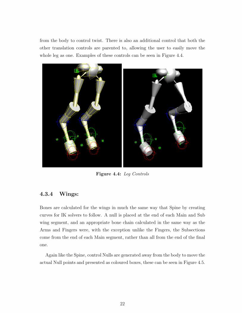
from the body to control twist. There is also an additional control that both the
other translation controls are parented to, allowing the user to easily move the
whole leg as one. Examples of these controls can be seen in Figure 4.4.
Figure 4.4: Leg Controls
4.3.4 Wings:
Bones are calculated for the wings in much the same way that Spine by creating
curves for IK solvers to follow. A null is placed at the end of each Main and Sub
wing segment, and an appropriate bone chain calculated in the same way as the
Arms and Fingers were, with the exception unlike the Fingers, the Subsections
come from the end of each Main segment, rather than all from the end of the final
one.
Again like the Spine, control Nulls are generated away from the body to move the
actual Null points and presented as coloured boxes, these can be seen in Figure 4.5.
22

Figure 4.5: Wing Controls
4.3.5 Bone Capture Buckets:
There is an area around each bone, referred to as the capture area, zone or bucket,
geometry within which can be tied to the movement of that bone. The rigging
tool automatically calculates and sets capture zones around every bone that it
generates, their extents decided upon based on the size of the particular segments
of the model the bone is within. This means that when the rig is attached to the
generated proxy geometry, the user will already have a good capture set up for
them so that all generated geometry should be captured correctly. A few minor
23
issues have been seen with edges of segments being captured by multiple buckets
which are too close but not from the same part of the creature i.e. the arm
buckets deliberately overlap slightly at their ends, but it is possible that a wing
bucket might intersect with the body or part of the arm, and this would need to
be rectified by the user.
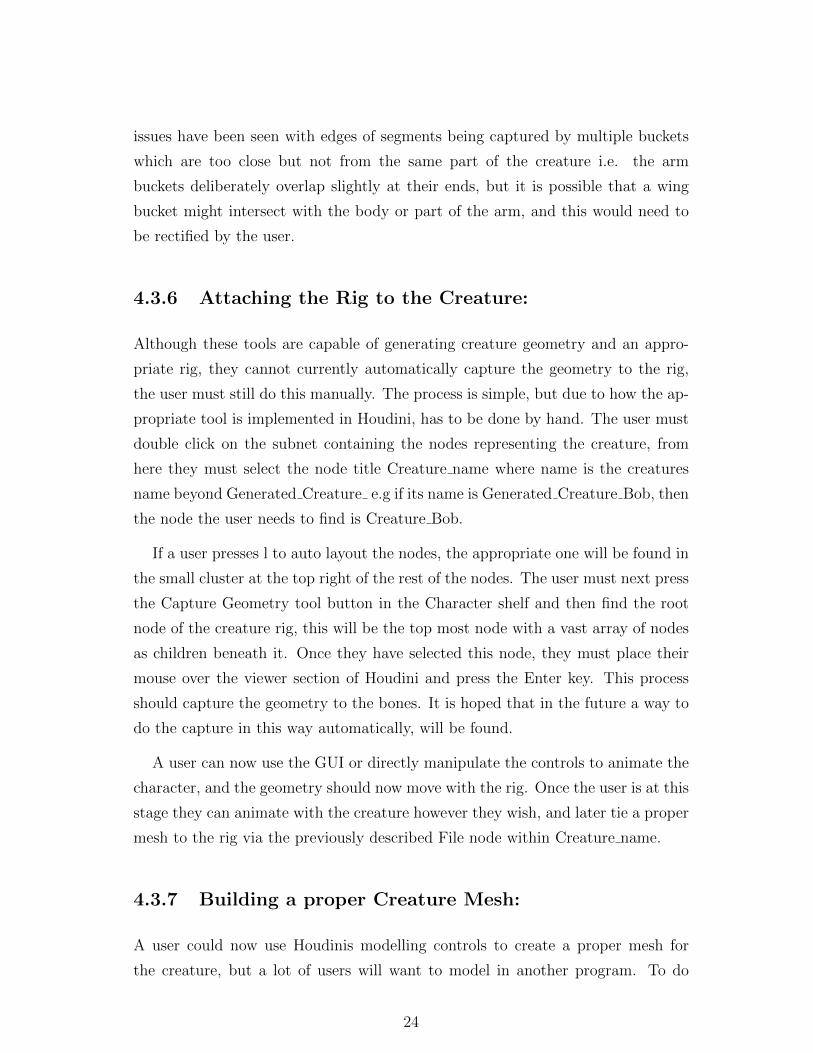
4.3.6 Attaching the Rig to the Creature:
Although these tools are capable of generating creature geometry and an appro-
priate rig, they cannot currently automatically capture the geometry to the rig,
the user must still do this manually. The process is simple, but due to how the ap-
propriate tool is implemented in Houdini, has to be done by hand. The user must
double click on the subnet containing the nodes representing the creature, from
here they must select the node title Creature name where name is the creatures
name beyond Generated Creature e.g if its name is Generated Creature Bob, then
the node the user needs to find is Creature Bob.
If a user presses l to auto layout the nodes, the appropriate one will be found in
the small cluster at the top right of the rest of the nodes. The user must next press
the Capture Geometry tool button in the Character shelf and then find the root
node of the creature rig, this will be the top most node with a vast array of nodes
as children beneath it. Once they have selected this node, they must place their
mouse over the viewer section of Houdini and press the Enter key. This process
should capture the geometry to the bones. It is hoped that in the future a way to
do the capture in this way automatically, will be found.
A user can now use the GUI or directly manipulate the controls to animate the
character, and the geometry should now move with the rig. Once the user is at this
stage they can animate with the creature however they wish, and later tie a proper
mesh to the rig via the previously described File node within Creature name.
4.3.7 Building a proper Creature Mesh:
A user could now use Houdinis modelling controls to create a proper mesh for
the creature, but a lot of users will want to model in another program. To do
24

this, they will want to export out the creatures geometry to use as a general guide
whilst modelling and to do so they must go to the Creature name node and enter
it. From the right-click menu on the Convert node, they can then choose Save
geometry and save out the geometry as a .obj file wherever they wish.
The .obj file can then be imported to another program and used as a guide with
the knowledge that the automatically set up capture buckets for the bones are
slightly larger than the proxy geo itself. Completed models can be imported back
into Houdini via the File SOP found inside the creatures Creature name node and
switched to be active via the Switch node.
Any animation that has been done with the rig should now work with the
proper creature mesh, however the user may need to refine the capture zones in
appropriately and perform weight painting to achieve a high fidelity capture of the
mesh to the rig. It is hoped in the future that an automated process for weight
painting could be incorporated to make the process easier for the user.
An example of a creature generated by these tools and a quickly made basic
mesh for it can be seen in Figure 4.6.
Figure 4.6: Proxy Geometry and Mesh made in Maya for a creature
25

Chapter 5
Genetic Algorithm
The Genetic Algorithm part of the program follows the standard GA processes
Crossover and Mutation as previously described in the report.
5.1 Crossover:
The algorithm picks a pair out of the possible parents in the parent pool (that the
user will have filled from the pool of creatures they have already generated) and
swaps over half of their genes to create an offspring. The gene swap may not be
possible in cases where the limb or segment numbers do not match between the
parents.
If the limb number doesn’t match (i.e. a gene from the third pair of arms of one
creature is selected to be applied to a creature with only two pairs of arms), then
the algorithm is able to generate new arms (and legs or wings) and then apply the
requested change to the required part. If the segment still does not exist (or the
limb already existed but the relevant segment did not) the program will currently
ignore this and move on. In the code the user will find a series of partially coded
algorithms that attempted to allow the tool to add in new segments, but unresolved
errors have prevented them from being accessible by the main algorithm. In the
future these would be completed in order to allow the GA to provide a more
complete solution. The reason these were not completed was due to a changed
focus to enhancing the rigging system and the associated additional work this
26

required for the relevant GUI and the required alterations and completions would
be a minor task during a future update.
5.2 Mutation:
The mutation algorithm is straightforward. The algorithm runs through the list
of parts in the genome and for each one randomly generates a number, if that is
lower than the mutation rate as provided by the user in the GA GUI, then it will
randomise the size value of that part - within the creatures Max and Min sizes for
the part in question. The algorithm runs through the list of parts three times in
order to account for potentially changing the size of a part in each of the X, Y and
Z dimensions as each should be considered a separate gene.
5.3 Use for Creature Variation:
There is also a secondary function of the GA, that can be of great use to the
user. If they choose only a single parent for the parent pool, the algorithm cannot
perform crossover (since they have exactly the same genes), however it can still
apply mutation. In this way, it is of use to a user who generates a creature, either
through the Creature Generator or as a result of use of the GA, that they find
very interesting but not quite right for their purposes.
By setting up the parent pool to consist of that creature only, and setting the
Mutation Rate appropriately, they will receive a generation of creatures that are
variations of the original. This in effect produces a number of individuals of the
species archetype of the original parent. The level of variation can be controlled
via the mutation rate.
Using the GA in this way, the user can either arrive at a variation they wish
to use, or else an entire population of similar creatures to rig and use as a species
in a project. An example of this process can be seen with a single parent seen in
Figure 5.1 and a generation of its progeny through mutation alone in Figure 5.2.
27

Figure 5.1: A Single Parent Creature
Figure 5.2: Children generated for the single Parent seen in Figure 5.1
28

Chapter 6
GUIs and Tool Controls
As previously stated, the program began life without any GUI, meaning that a
user would have to open up the shelf tool and directly edit the code to affect
changes in program behaviour. Once the features of the creature creation system
were more firmly defined and an understanding of the control and rigging scheme
was developed, it became possible to start to define a series of GUIs that could
interface with the Python and HOM script and give the user full, simple interactive
control over the program capabilities. There would be three necessary GUIs, one
for the main Creature Generation controls, one dealing with Genetic Algorithm
and breeding creatures and then some form of GUI for the generated creatures.
The initial idea was to package rigged creatures as Houdini Digital Assets so
that they could be easily shared; however creating Digital Assets through code
is severely lacking in example material. SideFXs page on HOM commands that
deals with Digital Asset creation (SideFX Houdini 11.0) provides the command to
turn a subnet into a Digital asset but it was not readily apparent how it would
be possible to programmatically make Houdini build an appropriate GUI for a
user, without attempting to work with Houdini code deeper than the HOM. Due
to the lack of coverage on such an ability and time constraints, it was decided to
create an external GUI to provide these controls to the user. At the end of the
project, rereading again Houdinis commands in relation to Digital Asset creation,
it seemed that it might be possible to promote the controls of the creature to a
single DA GUI via the ’addParmFolder’ and ’addParmTuple’ commands, but it
would require a lot of work to find out if these commands were usable in this way
29

and to establish a usable procedural method to do this if they were. At that stage
no time remained to properly explore this possibility, so the rest of this section
will detail the design and development of the external GUI system. Fully exploring
this idea would be a high priority for an update to the program.
Three separate GUI systems were built, the first developed was a static (i.e.
non-procedural GUI) that would present the user with all the options associated
with generating a creature or creatures. The second was also static and dealt
with GA control. The third was designed as procedural system for the control of
creatures generated by the first or second GUIs associated tools. It was procedural
in that the creature generation system can produce a wide variety of creatures
with many different combinations of limbs, leg designs, wings etc. and so when
activated for a given creature it would procedurally build a GUI containing all the
controls relevant for that particular creature.
There are two main supported methods for creating external GUIs in Houdini,
these are PyQT and wxPython. Houdini provides example code for running ei-
ther, including the necessary code to run the GUI in a separate thread (avoiding
Houdini being locked up otherwise when the GUI is activated) and opinion seems
to be divided as the which is the better to build with. wxPython was chosen
to implement the GUI for this project due to a good example of it being used
with Houdini being available online via the ’Python and Houdini’ webpage (Pate
2008) and due to issues with getting PyQt set up on the computer the project was
originally built on.
The example showed how a simple user interface employing wxPython can be
built with a simple GUI designer called wxGlade (wxGlade 2013), which was in-
stalled and used for this purpose. wxGlade allows a user to drag and drop GUI
components onto a window, position these components correctly and bind event
calls to buttons, control boxes, etc. All three GUIs were created in wxGlade which
generated the relevant wxPython code to create them when called. For the Crea-
ture GUI examples of all the things that would need to be procedurally generated
were made and then the resulting code was altered to allow the program to au-
tomatically build the relevant controls needed for a specific creature based on the
information contained within its genome.
30
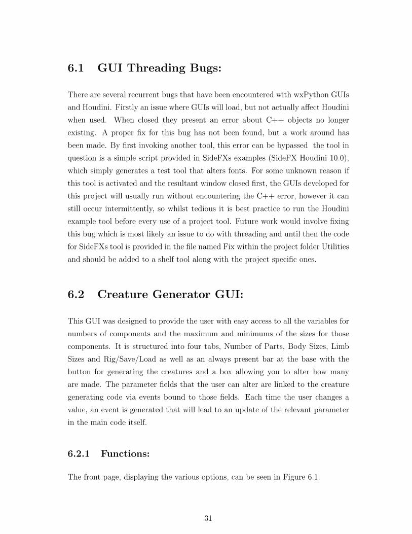
6.1 GUI Threading Bugs:
There are several recurrent bugs that have been encountered with wxPython GUIs
and Houdini. Firstly an issue where GUIs will load, but not actually affect Houdini
when used. When closed they present an error about C++ objects no longer
existing. A proper fix for this bug has not been found, but a work around has
been made. By first invoking another tool, this error can be bypassed the tool in
question is a simple script provided in SideFXs examples (SideFX Houdini 10.0),
which simply generates a test tool that alters fonts. For some unknown reason if
this tool is activated and the resultant window closed first, the GUIs developed for
this project will usually run without encountering the C++ error, however it can
still occur intermittently, so whilst tedious it is best practice to run the Houdini
example tool before every use of a project tool. Future work would involve fixing
this bug which is most likely an issue to do with threading and until then the code
for SideFXs tool is provided in the file named Fix within the project folder Utilities
and should be added to a shelf tool along with the project specific ones.
6.2 Creature Generator GUI:
This GUI was designed to provide the user with easy access to all the variables for
numbers of components and the maximum and minimums of the sizes for those
components. It is structured into four tabs, Number of Parts, Body Sizes, Limb
Sizes and Rig/Save/Load as well as an always present bar at the base with the
button for generating the creatures and a box allowing you to alter how many
are made. The parameter fields that the user can alter are linked to the creature
generating code via events bound to those fields. Each time the user changes a
value, an event is generated that will lead to an update of the relevant parameter
in the main code itself.
6.2.1 Functions:
The front page, displaying the various options, can be seen in Figure 6.1.
31

Figure 6.1: Creature Generator GUI Main Page
As previously indicated, there are some limits that must currently be observed
by the user, no more than two pairs of legs or one pair of wings.
The next two pages of the GUI, seen in Figure 6.2, allow the user to set size
ranges for all the component parts that will be generated in order to comprise the
creature.
32

Figure 6.2: Creature Generator GUI Second and Third Pages
The final tab presents a number of useful controls to the user and can be seen
in Figure 6.3.
33

Figure 6.3: Creature Generator GUI Final Page
A list box provides a list of all the creatures currently saved in the Creature
Pool, which represents the contents of the Saved Creatures folder in the project
file structure. In the context of this GUI, selected means that a user has selected
the appropriate subnet for a given creature in Houdinis Node view.
When a creature is selected, pressing Rename Selected will rename the creature
and its save file to Generated Creature + whatever they have entered into the
text box. Pressing Add Selected Creature to Pool will copy the creatures file to
the Saved Creatures folder and Rig Selected will invoke the Rigging algorithm on
34

that creature. Pressing Clear Screen will delete all current nodes.
If a user wishes to look at a previously saved creature, they can select it in the
list box and press View Creature From Pool, which will read the creatures file from
the Saved Creatures folder and rebuild it, centred at the world origin. A creature
loaded in such a way can then have its node selected and be subject to the above
operations.
6.2.2 Creating Digital Assets:
A user can also select a creature and press Create Digital Asset, which will auto-
matically create a Digital Asset (DA) for the creature, named with the same name
that the creature had. This was only implemented at the end of the project and
whilst successfully creating a DA out of a creature, does have some issues. Firstly
to create the DA, the code is set to suppress warnings about relative references,
which due to the way the code has been written, there are examples of a lack of.
The solvers reference to full file strings from the /obj level, and in theory could
be broken when the DA was invoked elsewhere. This problem was not actually
encountered during brief testing, but could theoretically appear.
Another issue is that each time you create an instance of the Asset, it is locked,
which is standard practice for DAs, but means that the rig is frozen as it is con-
tained within the Asset and so is locked. To get around this issue, if a user tries to
use the GUI tool while selecting a creature that is a DA, it will check its status as
a DA and upon finding it is one, unlock it, allowing the GUI controls to properly
interact with the rig. The problem with that approach is that any updates made
to master version of the DA, would never flow into the DA instance to match it to
the update.
The final problem with using the creatures as DAs is that when you call an
instance of one, its Rig will be initially broken, as the DA appends its own name
with a number, which results in the Rig looking for parts that do not exist. This
can be remedied by removing the number appended to the DAs name; however that
prevents having multiple instances of the same creature, as they would all need the
same name in order for the rigs to work, and multiple nodes with the same name
cannot coexist (at the same level) within a single Houdini file. One way around
35

this is to keep renaming and re-saving the same creature multiple times. Future
work would involve finding solutions to these problems that are more practical.
6.2.3 Creature Generator vs Creature Designer:
Although the GUI is primarily organised to help the user set up a variety of
creatures to be created, the user can also narrow the variables and restrict them
to a large extent, thus allowing them to create a highly specific type of creature.
Although this is not a true Creature Designer it is an approximation and shows
how the program could be extended to allow full Creature Designer capability to
be incorporated into it, or as a standalone tool. The idea was considered during
the development process, however it was decided to keep the code generalised as a
Creature Generator and allow the user to narrow the fields such that it has designer
like capability, without being a designer solely. The expansion of the code to allow
true designer functionality would be relatively minimal, requiring a new specific
GUI and potentially some additional functionality.
6.3 Genetic Algorithm GUI:
The Genetic Algorithm GUI needed to allow the user a good interface into the GA
algorithm, with simple, clear controls. The resultant GUI can be seen in Figure 6.4.
Figure 6.4: Genetic Algorithm for Creature Creature GUI
36

The user is presented with three list boxes, one containing all the creatures
that have so far been saved, one containing the parents to be used for the next
generation of creatures and one displaying the creatures that have been generated.
There are also controls for selecting the number of creatures and generating them
and for setting the Mutation Rate. The Mutation Rate is in terms of the percentage
chance that any given part will mutate during the breeding process, usually these
are set quite low, but if there are only two parents then a higher rate of mutation
might be desirable in order to get a better variety of creatures during the next
generation.
Buttons are also provided to add creatures from the Creature Pool to the Parent
Pool, to remove them from the Parent Pool and to save a generated creature, these
functions will move the creature files appropriately in the file structure (creatures
placed into the parent pool are copied rather than moved). A user could later
load a generated creature via the Creature Generator tool and rename/rig it as
they wished. This can also be done directly to any of the creatures that have been
created and are currently displayed in the window, however it is essential to shut
down the GA window first before calling the Creature Generator Tool, as there is
currently a bug that if more than one GUI is active at the same time, it will cause
Houdini to either lock-up or crash.
In Figure 6.5 several creatures are shown as the parents for a new generation
and Figure 6.6 shows a generation of creatures made from them.
Figure 6.5: Parent Creatures
37
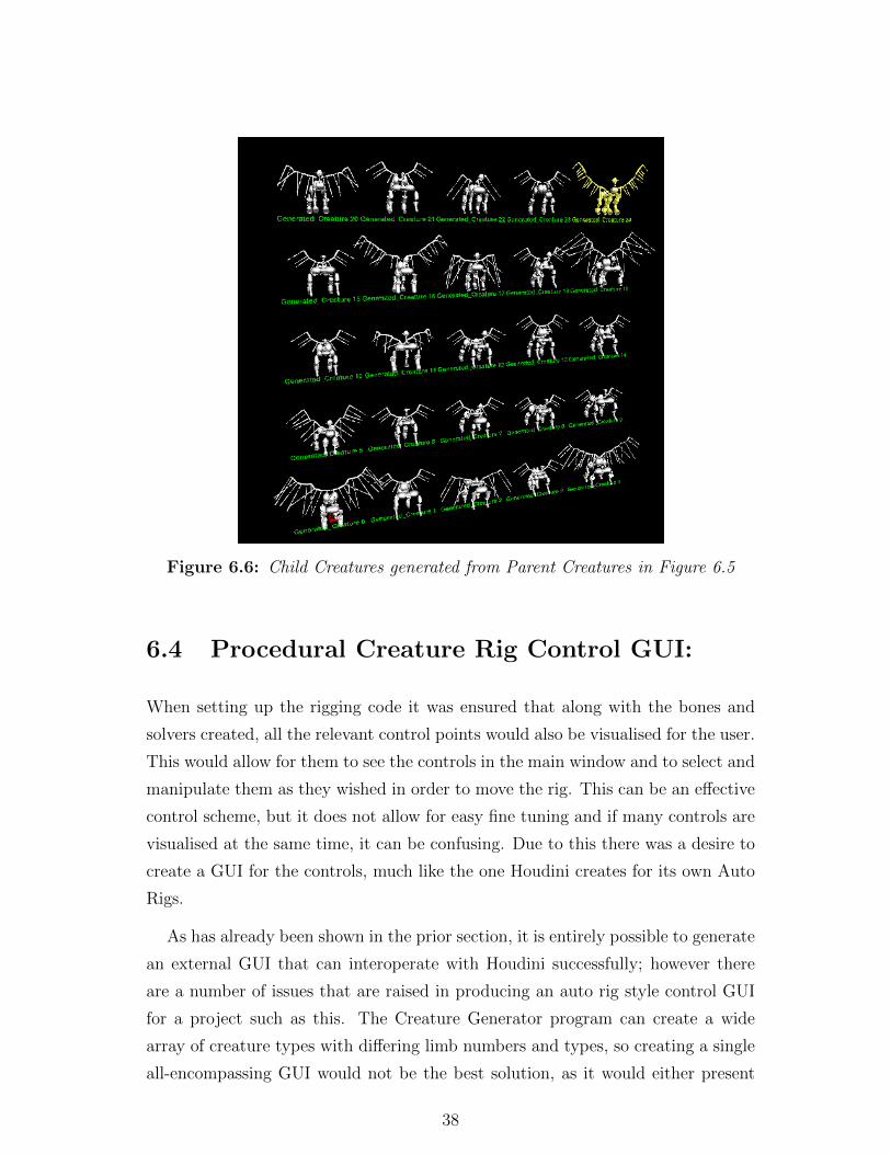
Figure 6.6: Child Creatures generated from Parent Creatures in Figure 6.5
6.4 Procedural Creature Rig Control GUI:
When setting up the rigging code it was ensured that along with the bones and
solvers created, all the relevant control points would also be visualised for the user.
This would allow for them to see the controls in the main window and to select and
manipulate them as they wished in order to move the rig. This can be an effective
control scheme, but it does not allow for easy fine tuning and if many controls are
visualised at the same time, it can be confusing. Due to this there was a desire to
create a GUI for the controls, much like the one Houdini creates for its own Auto
Rigs.
As has already been shown in the prior section, it is entirely possible to generate
an external GUI that can interoperate with Houdini successfully; however there
are a number of issues that are raised in producing an auto rig style control GUI
for a project such as this. The Creature Generator program can create a wide
array of creature types with differing limb numbers and types, so creating a single
all-encompassing GUI would not be the best solution, as it would either present
38

redundant controls to the user for parts a given creature doesnt have, or else it
wouldnt provide controls for parts that the creature does in fact have.
The best solution is a procedural approach whereby the GUI automatically
builds appropriate sections within itself to present only the controls required by
a given creature. The general algorithm for designing such a GUI is shown in
Figure 9.
This sort of functionality is not widely discussed in terms of wxPython, and in
order to let the program build as much as it needs, its labels must all be dynamic.
The best way it was found to achieve this was by making them Python dictionaries,
allowing easy iteration over them during ’For’ loops.
The resulting program can be slow to generate the GUI as it has to work out
what to actually generate for the GUI, every time it is run, taking 15 seconds or
so for particularly complex creatures, but usually less than 5 seconds for simpler
creatures. Due to the number of controls generated for them, creatures with large
wing structures are particularly susceptible to taking a longer time to build a GUI
for. As such, whilst this is an effective stopgap until a TD has written a full
DA interface, its slow speed to load likely makes it impractical for long term use.
Future work would focus on ways to build the GUI within Houdini, either as part
of a Digital Asset or through some other method. The resultant procedural GUI
can be seen in Figure 6.7.
39

Algorithm 9 Procedural Creature GUI Algorithm
for Each Leg doif Biped style then
Create Leg Translate ControlCreate Leg Twist Control
end ifif Quadruped style then
Create Full Leg Translate ControlCreate Upper Leg Translate ControlCreate Upper Leg Twist ControlCreate Lower Leg Translate ControlCreate Lower Leg Twist Control
end ifend forfor Each Arm do
Create Arm Translate ControlCreate Arm Twist Controlfor Each Hand do
Create Hand Rotation Controlfor Each Finger do
Create Finger Translate ControlCreate Finger Twist Control
end forend for
end forfor Each Wing do
Create Wing Translate ControlCreate Wing Rotate Control
end forfor Each Main Wing Segment do
Create Segment Translate ControlCreate Segment Rotate Control
end forfor Each Sub Wing Segment do
Create Sub Segment Translate ControlCreate Sub Segment Rotate Control
end forHead Translatefor Each Neck Segment do
Create Neck Segment Translate Controlend forfor Each Spine Segment do
Create Spine Translate Controlend forfor Each Tail Segment do
Create Tail Translate Control
end for
40

Figure 6.7: Creature GUI - Main Tab
The first page of the GUI allows the user to translate and rotate the creature
as a whole by manipulating its root. A set of check boxes are also provided in
order to alter which sets of controls are shown for the creature. A user can also
set whether or not to show the geometry of the creature and the bone rig and can
also display the capture areas for the bones.
The Arms tab provides separate sub tabs for each arm and hand, with as-
sociated controls for the translation and twist of the arms and fingers displayed
appropriately. This can be seen in Figure 6.8.
41
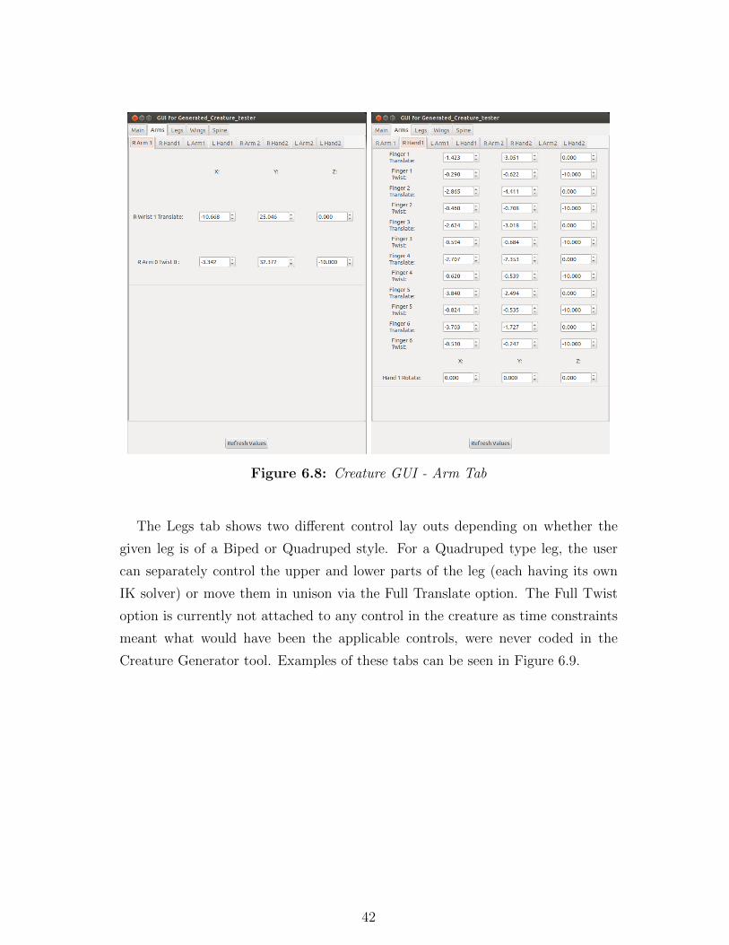
Figure 6.8: Creature GUI - Arm Tab
The Legs tab shows two different control lay outs depending on whether the
given leg is of a Biped or Quadruped style. For a Quadruped type leg, the user
can separately control the upper and lower parts of the leg (each having its own
IK solver) or move them in unison via the Full Translate option. The Full Twist
option is currently not attached to any control in the creature as time constraints
meant what would have been the applicable controls, were never coded in the
Creature Generator tool. Examples of these tabs can be seen in Figure 6.9.
42

Figure 6.9: Creature GUI - Leg Tab
Like the Arms tab, the Wings tab generates multiple sub tabs to separately
control the main sections of the wing and the subsection trailing from the main
ones. These controls can be seen in Figure 6.10.
43

Figure 6.10: Creature GUI - Wing Tab
The Spine tab separates into three sub tabs, one for the actual spine part itself,
one for the neck and head and one for the tail. There are only a set number of
spine controls, so these are consistent across GUIs, but the Neck and Tail tabs will
procedurally create as many controls as are required for the given creature. An
example of these controls can be seen in Figures 6.11 and 6.12.
44

Figure 6.11: Creature GUI - Neck and Spine Tabs
45
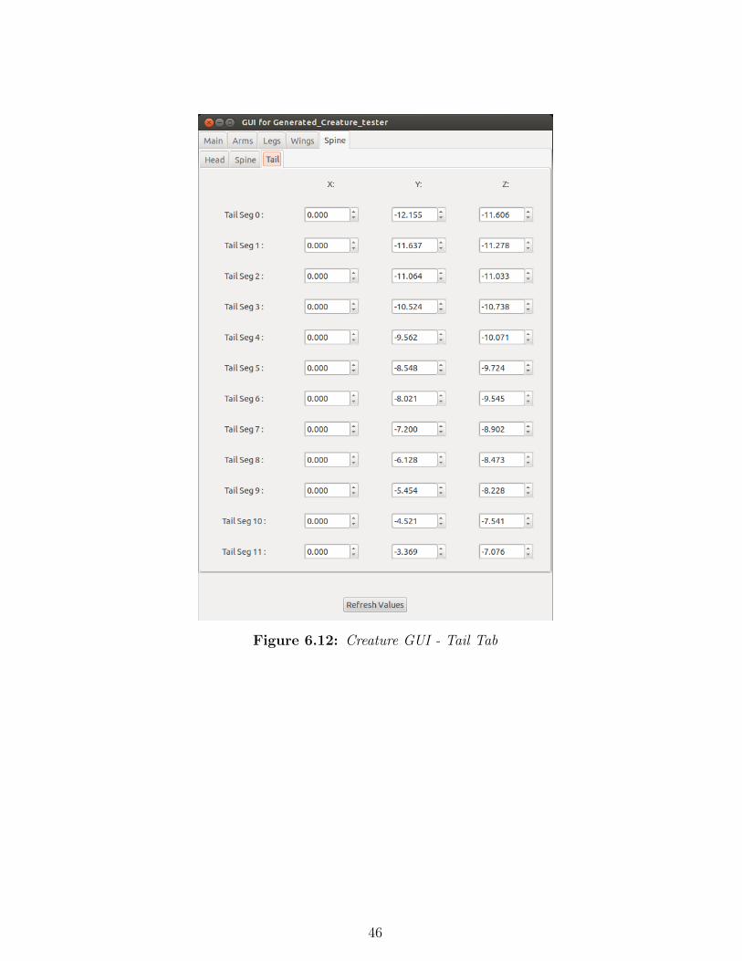
Figure 6.12: Creature GUI - Tail Tab
46

Chapter 7
Examples:
This report has already shown a number of examples of creatures generated by
the projects tools, this section shows a few more. Figure 7.1 shows a generation of
creatures.
Figure 7.1: A Generation of Creatures
47

Figure 7.2 shows creatures generated during the videos submitted with this
project.
Figure 7.2: Four Creatures seen generated in project videos
Figure 7.3 shows a child generated from the Genetic Algorithm operating on the
creatures of Figure 7.2. Next to this creature (on the right) is a creature generated
by using the creature on the left as a lone parent with high mutation, to arrive at
a variant.
48

Figure 7.3: Parent (Left) generated as child of Figure 7.2 and its Child (right)generated via Mutation of Parent alone
Figure 7.4 shows an example of an arm that has been manipulated via the
controls generated by these tools, as its underlying bones, the proxy geometry
originally generated and a mesh modelled in Maya and read into the creatures
geometry.
49

Figure 7.4: Bone, Proxy Geometry and Mesh of a Creature Arm
50

Chapter 8
Conclusion
Through undertaking this project a great deal has been learnt about both scripting
with Python and tool writing in Houdini. Three tools have been created, the first
to both generate and rig creatures, the second to breed creatures together to create
new designs and the last to generate practical, procedural GUIs for these creatures.
The Creator Generator tool provides a lot of scope for user interaction in defining
the creature types generated and allows the user to save, load and generate rigs
for any creature produced. Extending this to allow even more user control would
be beneficial in the future.
The Genetic Algorithm tool allows the breeding of multiple selected parents to
produce offspring via Crossover and Mutation functions and has the added benefit
of allowing a single parent to be used to generate variations on that parent leading
to a refined creature of interest, or a species of individuals sharing the same form
factor, or creature archetype.
The Procedural Creature GUI tool is a single program that can generate a
bespoke GUI for any creature created by the other two tools. It will procedurally
build itself to have the controls required for any given creature.
The tools were never designed to be entirely comprehensive, as has been noted
throughout this report, but it is believed they show the power that a system like this
has. Taking the project forward it could be further developed with the suggestions
made earlier in the report, or used as the basis for a more complete Creature
Designer and Auto Rigger, with more precise controls and fewer limitations on
51

part numbers and types.
The Genetic Algorithm is an interesting part of the tools, but it is understood
that different users would find it of differing levels of usefulness. It is believed that
updates to the Creature Generator code, removing the current limitations would
lend greater strength and utility to the Genetic Algorithm tool.
All the Python code is fully transferable to other software packages such as
Maya, so the general algorithms could be employed in other programs, with the
HOM commands swapped out for relevant commands in another package.
The project stands as a proof of concept that a system such as this is possible
and could be a useful tool for any TD or animator. The pipeline for creature
creation is different to the standard one for creating creatures from concept art
onwards, but could provide time savings and potentially come up with designs
that a user wishes to use but might not have otherwise considered themselves.
The ability to both generate and rig a character automatically has been shown
and this capability could be very useful, providing time savings in rig creation.
8.1 Future Work:
Commentary on specific avenues of future work have been made throughout this
report, largely in regards to detailing limitations to remove, capabilities to extend
and bugs to remove. The following is a brief list of the most important areas for
future work:
• Fix the GUI threading issues
• Extend the parts the generator can create and remove current part number
limitations
• Extend the Genetic Algorithm to be capable of adding additional segments
• Improve code by extracting relevant shared algorithms to call as modules
• Explore additional control schemes for the auto rig function
• Explore further how to create useful DAs from the creatures with Houdini
based (rather than external) GUIs
52

Bibliography
R. Akbari & K. Ziarati (2011). ‘A multilevel evolutionary algorithm for optimizing
numerical functions’. International Journal of Industrial Engineering Computa-
tions;Apr2011, Vol. 2 Issue 2, p419 .
M. Ando & M. Hagiwara (2009). ‘3D character creation system using Kansei rule
with the fitness extraction method’. In Fuzzy Systems, 2009. FUZZ-IEEE 2009.
IEEE International Conference on, pp. 1507–1512.
P. Bentley (1999). ‘Aspects of Evolutionary Design by Computers’. In R. Roy,
T. Furuhashi, & P. Chawdhry (eds.), Advances in Soft Computing, pp. 99–118.
Springer London.
E. Goldfinger (2004). Animal Anatomy For Artists - The Elements of Form, chap.
Basic Body Plan, pp. 4–5. Oxford University Press.
J. H. Holland (1992). Adaptation in natural and artificial systems. MIT Press,
Cambridge, MA, USA.
M. Lewis, et al. (2001). ‘Aesthetic Evolutionary Design with Data Flow Networks’
For a little over a decade, software has been created which allows for the design
of visual content by aesthetic evolutionary design (AED). The great majority
of these AED systems involve custom software intended for breeding entities
within one fairly narrow problem domain, e.g., certain classes of buildings, cars,
images, etc. Only a very few generic AED systems have been attempted, and ex-
tending them to a new design problem domain can require a significant amount
of custom software development. High-end computer graphics software packages
have in recent years become sufficiently robust to allow for flexible specification
and construction of high-level procedural models. These packages also provide
extensibility, allowing for the creation of new software tools. One component
53

of these systems that enables rapid development of new generative models and
tools is the visual data flow network. One of the first CG packages to employ
this paradigm was Houdini. A system constructed within Houdini that allows for
very fast generic specification of evolvable parametric prototypes is described.
The real-time nature of the software, when combined with the interlocking data
networks, allows not only for vertical ancestor/child populations within the de-
sign space to be explored, but also allows for fast horizontal exploration of the
potential population surface. Several example problem domains will be presented
and discussed. 1.
T. Ogura & M. Hagiwara (2013). Advances in Affective and Pleasurable Design,
chap. 3D Character Creation System Based on Sensibility Rule Extraction. CRC
Press.
S. Pate (2008). ‘Python and Houdini - Implementation and workflow benefits’.
D. Rowland & F. Biocca (2000). ‘Evolutionary co-operative design between human
and computer: implementation of ’the genetic sculpture park”. In Proceedings
of the fifth symposium on Virtual reality modeling language (Web3D-VRML),
VRML ’00, pp. 75–79, New York, NY, USA. ACM.
SideFX (Houdini 10.0). ‘HOM wxPython Example: Writ-
ing Custom GUIs inside Houdini’. Online. Available from:
http://www.sidefx.com/docs/houdini10.0/hom/cookbook/wxPython/Node#createDigitalAsset
[Accessed July 2013].
SideFX (Houdini 11.0). ‘hou.Node class’. Online. Available from:
http://www.sidefx.com/docs/houdini11.0/hom/hou/Node#createDigitalAsset
[Accessed July 2013].
K. Sims (1994). ‘Evolving virtual creatures’. In Proceedings of the 21st annual
conference on Computer graphics and interactive techniques, SIGGRAPH ’94,
pp. 15–22, New York, NY, USA. ACM.
J. Venter & A. Hardy (2007). ‘Generating plants with gene expression program-
ming’. In Proceedings of the 5th international conference on Computer graphics,
virtual reality, visualisation and interaction in Africa, AFRIGRAPH ’07, pp.
159–167, New York, NY, USA. ACM.
54

wxGlade (2013). ‘wxGlade’. Online. Available from:
http://wxglade.sourceforge.net/ [Accessed July 2013].
N. Yamamoto, et al. (2011). ‘Skeleton-based diverse creature design tool for mass
production’. In SIGGRAPH Asia 2011 Posters, SA ’11, pp. 11:1–11:1, New
York, NY, USA. ACM.
55