Creating Estimated S-N Diagram - UPRMacademic.uprm.edu/pcaceres/Courses/INME4011/MD-6B.pdfCreating...
56
Creating Estimated S-N Diagram These equations are used to determine the corrected endurance limit S e or the corrected fatigue strength S f at a particular number of cycles N in the high-cycle region of the S-N diagram. For the low-cycle region the following estimates are found: ut m ut m S S loading axial S S bending 75 . 0 ......... : _ 9 . 0 .......... .......... : = = S m material strength at 10 3 cycles
Transcript of Creating Estimated S-N Diagram - UPRMacademic.uprm.edu/pcaceres/Courses/INME4011/MD-6B.pdfCreating...

Creating Estimated S-N Diagram
These equations are used to determine the corrected endurance limit Seor the corrected fatigue strength Sf at a particular number of cycles N in the high-cycle region of the S-N diagram. For the low-cycle region the following estimates are found:
utm
utm
SSloadingaxialSSbending
75.0.........:_9.0....................:
==
Sm material strength at 103 cycles

The equation of the line from Sm to Sf (or Se) is: bn aNS =
for materials that possess an endurance limit the coefficients (a, b) can be calculated from the following two points:

for materials that do not possess an endurance limit, use:
Note: NbaSn loglog)log( +=
Boundary conditions:
82
62
31
105__
10__
10__
×===
===
===
NNatSS
NNatSS
NNatSS
fn
en
mn
Material with endurance limit
Material without endurance limit
21 loglog............log1 NNzwhereSS
zb
e
m −=⎟⎟⎠
⎞⎜⎜⎝
⎛=
Material with endurance limit N1=103 and N2=106
N2 (106) z1.0 -3.0005.0 -3.69910.0 -4.00050.0 -4.699100.0 -5.000500.0 -5.699
bn aNS =

Problem: Create an estimated S-N diagram for a steel bar and define its equations. How many cycles of life can be expected if the alternating stress is 100MPa.
Given: The Sut has been tested at 600MPa. The bar is 150mm square and has a hot rolled finish. The operating temperature is 500oC maximum. The loading will be fully reverse bending.
Assumptions: Infinite life is required (ductile steel with endurance limit). A reliability factor of 99.9% will be used.
Solution:
MPaSS ute 3005.0' ==
Loading factor is bending
0.1=loadk

The part is not round:
mmmmAd
mmmmmmbhA
equiv 2.1210766.0
11250766.0
112515015005.005.02
95
295
===
=××==
The size factor:
747.0)2.121(189.1
189.1.........:2508_097.0
097.0
==
=≤≤−
−
size
size
k
dkmmdmmfor equivalent
Surface Factor:
584.0)600(7.57 718.0 =×=×= −butSurface SAk

Temperature Factor: ( ) ( ) 71.04505000058.014500058.01 =−−=−−= TkTemp
Reliability Factor 753.0=yreliabilitk
Corrected Endurance limit:
MPaS
SkkkkkS
e
eyreliabilitTempsurfsizeloade
70300753.071.0584.0747.00.1
'
=×××××=
×××××=

Creating the S-N diagram
MPaSSbending utm 5406009.09.0....................: =×==
295765.070
540log31log1
−=⎟⎠⎞
⎜⎝⎛−=⎟⎟
⎠
⎞⎜⎜⎝
⎛=
e
m
SS
zb
7.4165)295765.0(3)540log(3)log()log(
=−×−=−=
abSa m
NbSaNbaS
n
n
log)log(logloglog)log(
−=+=
cyclesNNMPa
5
295765.0
100.3)7.4165(100
×=
×= −
N2 (106) z1.0 -3.0005.0 -3.69910.0 -4.00050.0 -4.699100.0 -5.000500.0 -5.699
bn aNS =

Kt is the theoretical stress concentration factor.Notch sensitivity – q . Materials have different sensitivity to stress concentrations, referred to as the notch sensitivity of the material. In general, the more ductile a material is, the less sensitivity to notches it is.It depends on notch radius, the smaller the radius, the less sensitive the material is
Notches and Stress Concentrations
where a is Neubers constant and it is solely a function of the material, and r is the notch radius (both expressed in inches).
Neuber, Kuhn and Peterson have developed an approach to notch sensitivityPeterson’s equation


Problem: A rectangular step steel bar (as shown below) is to be loaded in bending. Determine the stress-concentration factor for the given dimensions.
Given: H=2in, h=1.8in, r=0.25in. The material has Sut=100kpsi.
Solution:
11.18.1
2
1388.08.125.0
==
==
hHhr
Kt=1.56 89.0
25.0062.01
1
1
1062.0
=+
=+
=
=
ra
q
a
( )( )
50.1
156.189.01
11
=
−+=
−+=
f
f
tf
K
K
KqK

Design of a Cantilever Bracket for Fully Reversed BendingProblem: Design a cantilever bracket to support a fully reversed bending load of 500-lb amplitude for 109 cycles with no failure. Its dynamic deflection can not exceed 0.01in.. Calculate the safety factor.
Given: Beam width (b) = 2in ; beam depth over length (d) = 1in ; beam depth in wall (D) = 1.125in ; fillet radius (r) = 0.3in ; applied load amplitude at point (F) = 500-lb ; beam length (l) = 6in ; distance to load (a) = 5in ; distance for deflection calculation (lx) = 6in ; Modulus of elasticity (E) = 3x10⁷psi ; ultimate tensile strength (Sut) = 80kpsi for a steel. The cantilever has been machined and operates at a temperature of 120oF

Solution:
5.021
2
1667.012
1212
2500500
33
===
=×
==
−=×===
dc
bdI
inlbaFMlbFR
a
a
Bending at the root
3.013.0
125.11125.1
==
==
drdD
33.1=tK
psiI
Mcnoma 7500
1667.05.02500
, =×
==σ
lbF
lbF
mean
amplitude
0
500
=
=
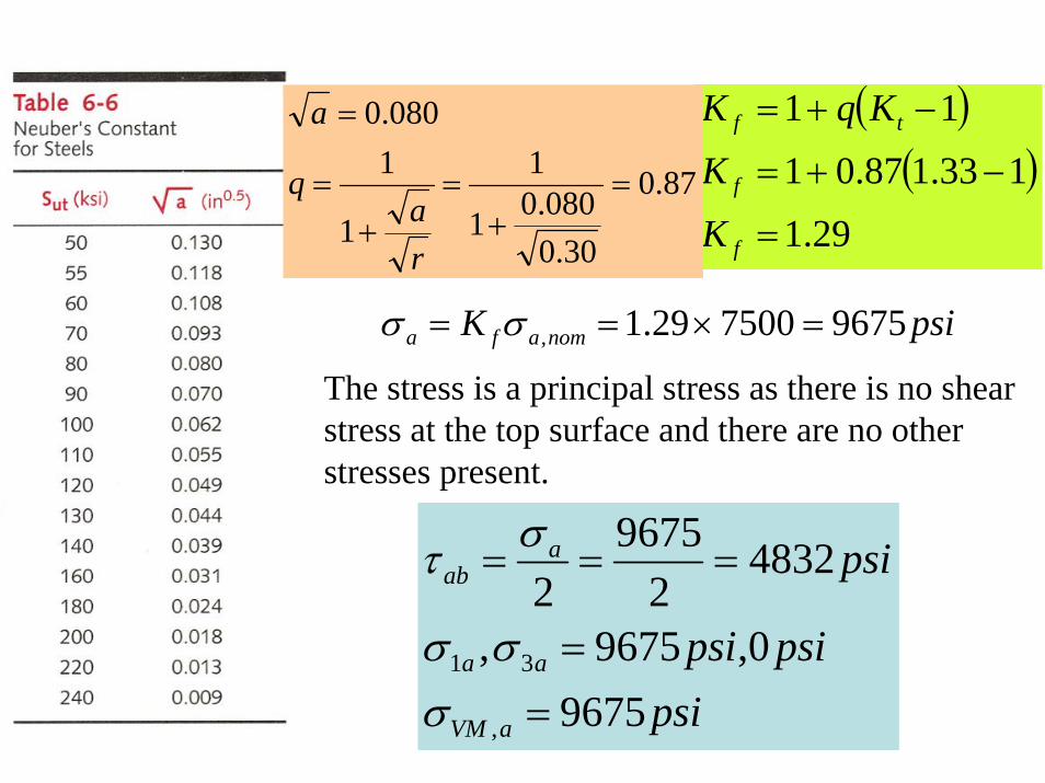
( )( )
29.1
133.187.01
11
=
−+=
−+=
f
f
tf
K
K
KqK
87.0
30.0080.01
1
1
1080.0
=+
=+
=
=
ra
q
a
psiK nomafa 9675750029.1, =×== σσ
The stress is a principal stress as there is no shear stress at the top surface and there are no other stresses present.
psipsipsi
psi
aVM
aa
aab
96750,9675,
48322
96752
,
31
==
===
σσσ
στ
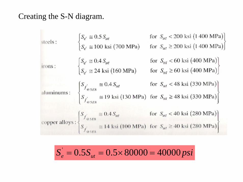
psiSS ute 40000800005.05.0' =×==
Creating the S-N diagram.

inAd
indbA
equivalent 14.10766.0
1.02105.005.0
95
295
==
=××==

Size factor:
inAd
indbA
equivalent 14.10766.0
1.02105.005.0
95
295
==
=××==
( ) 86.014.1869.0
869.0.........:.103.0_097.0
097.0
=×=
=≤≤−
−
size
size
k
dkindinfor
Load Factor: Pure bending 1=loadk
Surface factor:
( ) 845.0807.2 265.0 =×== −butsurf ASk

Temperature factor: 0.1=Tempk
Reliability factor: As only ten of these parts are required, a high % reliability is chosen (99.9%) 753.0=yreliabilitk
Corrected endurance limit:
psiSpsiS
SkkkkkS
e
e
eyreliabilitTempsurfsizeloade
2184340000753.01845.086.01
'
=×××××=
=
Predicted Safety factor: 26.2967521843
,
===aVM
esf
Snσ
The beam deflection y is calculated
( )[ ] ( )( ) ( )[ ] inaxaxxEIFy 005.0566536
1667.010365003
6323
7323 −=−−××−
×=−−−=

Many repeating and fluctuating stresses have non-zero mean components and these must be taken into account.
Designing for fluctuating Uniaxial Stresses
⎟⎟⎠
⎞⎜⎜⎝
⎛−=
ut
mea S
S σσ 1Modified-Goodman line (for design)
Gerber Parabola (for analysis of failed parts)
⎟⎟⎠
⎞⎜⎜⎝
⎛−= 2
2
1ut
m
SSea
σσ

Design of a Cantilever Bracket for Fluctuating BendingProblem: Design a cantilever bracket to support a fluctuating bending load of 100 to 1100-lb amplitude for 109 cycles with no failure. Its dynamic deflection can not exceed 0.02in.. Calculate the safety factor.
Given: Beam width (b) = 2in ; beam depth over length (d) = 1in ; beam depth in wall (D) = 1.125in ; fillet radius (r) = 0.3in ; maximum applied load amplitude at point (F) = 1100-lb ; minimum applied load amplitude at point (F) = 100-lb ; beam length (l) = 6in ; distance to load (a) = 5in ; distance for deflection calculation (lx) = 6in ; Modulus of elasticity (E) = 3x10⁷psi ; ultimate tensile strength (Sut) = 80kpsi for a steel; yield strength (Sy) = 60kpsi. The cantilever has been machined and operates at a temperature of 120oF

Solution:
inlbinlbaFMinlbinlbaFMinlbinlbaFM
lbFRlbFRlbFR
lbFFF
lbFFF
MaxMax
mm
aa
MaxMaxmmaa
MinMaxa
MinMaxm
−=×==−=×==−=×==
======
=−
=−
=
=+
=+
=
5500511003000560025005500
1100.....600.......500
5002
10011002
6002
10011002
5.021
2
1667.012
1212
33
===
=×
==
dc
bdI
psiI
cM
psiI
cM
mnomm
anoma
90001667.0
5.03000
75001667.0
5.02500
,
,
=×
==
=×
==
σ
σ
3.013.0
125.11125.1
==
==
drdD
33.1=tK

Verify that the stress concentration are below yield strength of the material.
psipsiK
psipsiK
psiSpsiI
cMKK
KKthenSKif
nommmfm
nomafa
yMax
fMaxf
ffmyMaxf
11610900029.1
9675750029.1
60000212811667.0
5.0550029.1
..............
,,
,
=×==
=×==
=<=×
==
=<
σσ
σσ
σ
σ
( )( )
29.1
133.187.01
11
=
−+=
−+=
f
f
tf
K
K
KqK
87.0
30.0080.01
1
1
1080.0
=+
=+
=
=
ra
q
a

Calculate the Von Mises for the alternating stress and the mean stress
psi
psi
mxymymxmymxm
axyayaxayaxa
11610030116100116103
967503096750967532222
,,,2,
2,
'
2222,,,
2,
2,
'
=×+×++=+−+=
=×+×++=+−+=
τσσσσσ
τσσσσσ
Generating a S-N : Size factor:
inAd
indbA
equivalent 14.10766.0
1.02105.005.0
95
295
==
=××==
( ) 86.014.1869.0
869.0.........:.103.0_097.0
097.0
=×=
=≤≤−
−
size
size
k
dkindinfor
Load Factor: Pure bending 1=loadk
Surface factor: ( ) 845.0807.2 265.0 =×== −butsurf ASk
Temperature factor: 0.1=TempkReliability factor: As only ten of these parts are required, a high % reliability is chosen (99.9%)
753.0=yreliabilitk

Corrected endurance limit:
psiSpsiS
SkkkkkS
e
e
eyreliabilitTempsurfsizeloade
2184340000753.01845.086.01
'
=×××××=
=
Various safety factors can be calculated:It assumes that the alternate and mean component will have a constant ratio.
70.1
8000011610
218839675
1=
+=fn
The beam deflection y is calculated
( )[ ] ( )( ) ( )[ ] inaxaxxEI
Fy Max 012.05665361667.01036
110036
3237
323 −=−−××−×
=−−−=
82.2116109675
60000=
+=
+=
ma
yy
Sn
σσ
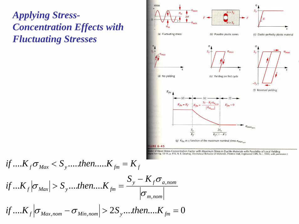
Applying Stress-Concentration Effects with Fluctuating Stresses
0........2....
...........
..............
,,
,
,
=>−
−=>
=<
fmynomMinnomMaxf
nomm
nomafyfmyMaxf
ffmyMaxf
KthenSKif
KSKthenSKif
KKthenSKif
σσ
σσ
σ
σ

Multiaxial Fluctuating Stresses
Problem: Determine the safety factors for the brackets tube shown.
Given:Material: 2024-T4 aluminum with Sy=47ksi and Sut=68ksi.Tube length (l) = 6in. ; arm (a) = 8in. ; Tube outside diameter (OD) = 2in ; Tube inside diameter (ID) = 1.5in The applied load varies sinusoidally from F=340 to -200lb
Assume finite life design 6x10⁷ cycles.The component has been machined. It operates at RT and with 99.9% reliability.
Notch radius at the wall = 0.25inStress concentration factor for bending = 1.7For shear = 1.35

Solution:Aluminum does not have an endurance limit. As Sut > 48kpsi then Sf=19kpsi at 5x10⁸ cyclesCalculation of the correction factors:
Load Factor: Bending 1=loadk097.0869.0.........:.103.0_ −=≤≤ equivalentsize dkindinforSize factor:
895.0)74.0(869.0
74.00766.0
010462.00766.0
010462.0
097.0
295
295
=×=
===
=
−ink
indAd
dA
size
equivalent
This value is used despite the fact that both bending and torsion are present.

Surface factor: (machined) ( ) 883.0687.2 265.0 =×== −butsurf ASk
Temperature factor: (room temperature) 0.1=Tempk
Reliability factor: As only ten of these parts are required, a high % reliability is chosen (99.9%)
753.0=yreliabilitk
Corrected endurance limit:
psiS
psiS
SkkkkkS
f
f
eyreliabilitTempsurfsizeloadf
11299
19000753.01883.0895.01
'
=
×××××=
=
At 5x10⁸ cycles
The problem calls for a life of 6x10⁷ cycles, so the strength value at that life must be estimated.
ksiSSbending utm 2.61680009.09.0.....: =×==
1287.01129961200log
699.51log1
−=⎟⎠⎞
⎜⎝⎛−=⎟
⎟⎠
⎞⎜⎜⎝
⎛=
f
m
SS
zb
148929)1287.0(3)61200log(3)log()log(
=−×−=−=
abSa m
( )psiS
NS
n
n
14846106)148929()148929( 1287.071287.0
=××=×=
−−bn aNS =
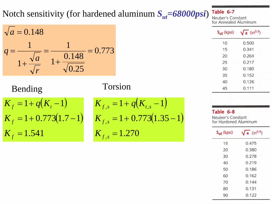
Notch sensitivity (for hardened aluminum Sut=68000psi)
( )( )
541.1
17.1773.01
11
=
−+=
−+=
f
f
tf
K
K
KqK
773.0
25.0148.01
1
1
1148.0
=+
=+
=
=
ra
q
a
Bending Torsion
( )( )
270.1
135.1773.01
11
,
,
,,
=
−+=
−+=
sf
sf
stsf
K
K
KqK

The bracket tube is loaded in bending (as a cantilever) and in torsion. All the loading are maximum at the wall. Need to find the alternating and mean components of the applied force, moment andtorque at the wall.
inlbinlbaFinlbinlbaF
inlbinlblFMinlbinlblFM
lbFFF
lbFFF
mm
aa
mm
aa
MinMaxm
MinMaxa
−=×==Τ−=×==Τ−=×==−=×==
=−+
=+
=
=−−
=−
=
5608702160827042067016206270
702
)200(3402
2702
)200(3402

The fatigue stress concentration factor for the mean stresses depends on the relationship between the maximum local stress in the notch and the yield strength
270.1.........
541.1.......
4700058555369.0
16340541.1
..............
==
==
=<=××
==
=<
ffm
ffm
yMax
fMaxf
ffmyMaxf
KKtorsion
KKbending
psiSpsiI
lcFKK
KKthenSKif
σ
σ
The largest tensile bending stress will be at the top or bottom of the cantilever. The largest torsional shear stress will be all around the outer circumference of the tube.

psiJ
rTK
psiI
cMK
psiJrT
K
psiI
cMK
mmeanshearFtorsionm
mfmm
ashearFtorsiona
afa
663074.1
1560270.1
12055369.0
1420541.1
2556074.1
12160270.1
46495369.0
11620541.1
,,,
,,
=×
==
=×
==
=×
==
=×
==
τ
σ
τ
σFinding the amplitude and mean components due to bending and torsion.
Finding the alternating/amplitude and mean Von Mises stresses at A.
psi
psi
m
mxymymxmymxm
a
axyayaxayaxa
166466330120501205
3
6419255630464904649
3
222'
2,,,
2,
2,
'
222'
2,,,
2,
2,
'
=×+×−+=
+×−+=
=×+×−+=
+×−+=
σ
τσσσσσ
σ
τσσσσσ

Various safety factors can be calculated:It assumes that the alternate and mean component will have a constant ratio.
2.2
680001664
148466419
1=
+=fn
82.516646419
47000=
+=
+=
ma
yy
Sn
σσ
We need to check the shear due to transverse loading at point B in the neutral axis where the torsional shear is also maximal.
psipsi
psiAVK
psiAVK
torsionmtransversemtotalm
torsionatransverseatotala
mmeanshearftransversem
ashearftransversea
72966312930552556499
129374.1
702270.12
499374.12702270.12
,,,
,,,
,,,
,,
=+=+=
=+=+=
=×
==
=×
==
ττττττ
τ
τ
IbVQ
=τ

psi
psi
m
mxymymxmymxm
a
axyayaxayaxa
137279230000
3
5291305530000
3
222'
2,,,
2,
2,
'
222'
2,,,
2,
2,
'
=×+×−+=
+×−+=
=×+×−+=
+×−+=
σ
τσσσσσ
σ
τσσσσσ
Safety factors: It assumes that the alternate and mean component will have a constant ratio.
7.2
680001372
148465291
1=
+=fn
05.713725291
47000=
+=
+=
ma
yy
Sn
σσ
Both points A and B are safe against fatigue failure.

We have a rotating shaft, as shown, made of AISI 1040 hot rolled (Sy = 290MPa; Sut = 524MPa; E = 210GPa). Determine the Moment it can support for 100,000 cycle life.
05.042.0
5.146
==
==
drdD
03.2=tK

097.0
097.0
189.1.........:2508_
869.0.........:.103.0_
1.....:)8_(3.0_
−
−
=≤≤
=≤≤
=≤
dkmmdmmfor
dkindinfor
kmmindfor
size
equivalentsize
size

Determine the Fatigue Stress Concentration
( )( )
791.1
103.2768.01
11
=
−×+=
−+=
f
f
tf
K
K
KqK
768.0
4.25/2085.01
1
1
1085.0
=+
=+
=
=
ra
q
a
TS=524MPa=76ksi( )
085.0
080.080768070
080.0093.08070
080.0093.08076080.0
=
+−⎟⎠⎞
⎜⎝⎛
−−
=
−−
=−−
a
a
a
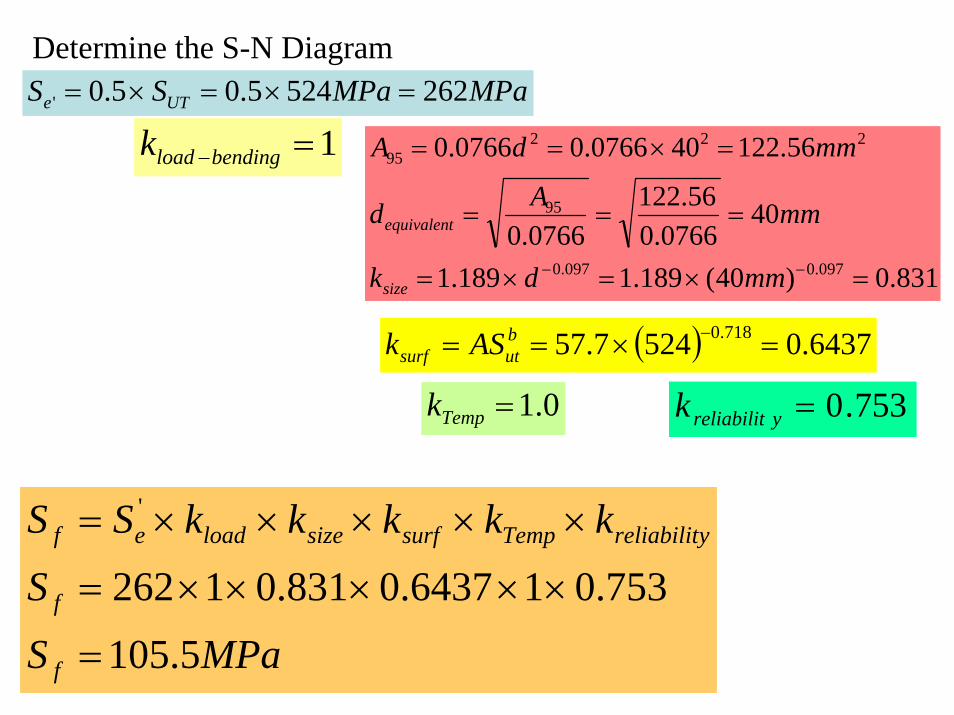
Determine the S-N Diagram
MPaS
S
kkkkkSS
f
f
yreliabilitTempsurfsizeloadef
5.105
753.016437.0831.01262
'
=
×××××=
×××××=
MPaMPaSS UTe 2625245.05.0' =×=×=
1=−bendingloadk
831.0)40(189.1189.1
400766.0
56.1220766.0
56.122400766.00766.0
097.0097.0
95
22295
=×=×=
===
=×==
−− mmdk
mmAd
mmdA
size
equivalent
( ) 6437.05247.57 718.0 =×== −butsurf ASk
0.1=Tempk 753.0=yreliabilitk

0.9x524=471.6MPa
105.5MPa
105
MPaS
S
S
aNbS
f
f
f
f
8.173
24.2)log(
)2108log()10log()10log()10log(
)5.105log()6.471log()log(
)log()log()log(
563
=
=
+×−−
=
+×=
21677.05.1056.471log
31log1
−=⎟⎠⎞
⎜⎝⎛−=⎟⎟
⎠
⎞⎜⎜⎝
⎛=
e
m
SS
zb
bn aNS =
N2 (106) z
1.0 -3.000
5.0 -3.699
10.0 -4.000
50.0 -4.699
100.0 -5.000
500.0 -5.6992108
)21677.0(3)6.471log(3)log()log(=
−×−=−=a
bSa m
NbSaNbaS
n
n
log)log(logloglog)log(
−=+=

Calculate the stress (amplitude and mean)
M
MMI
My
MMI
My
rI
Amplitude
Mean
Min
Max
××=
=
××−=×
×−=−=
××=×
×==
×=×
==
−
−
−
5
56
56
644
105915.1
0
105915.1101257.002.0
105915.1101257.002.0
101257.04
)02.0(4
σ
σ
σ
σ
ππ
Stress Concentration
mNMoment
MPaS
M
MK
fCorrectedAmplitude
CorrectedAmplitude
AmplitudefCorrectedAmplitude
−=
==
××=
×××=×=
−
−
−
7.609
8.173
1028504.0
105915.1791.16
5
σ
σ
σσ

P
R
The load P varies between Pmax=8000lb and a Pmin=-4000lb
The load R varies between +/-1000lb
Given:
AISI 4340 Oil Quenched at 855oC and Temper at 230oC 4hours (Sy=200ksi; Sut=260ksi)Machined component working at room temperature and a reliability of 99.99%
Problem: Determine the safety factor for the component shown below. Consider all stress concentration factors at the wall equals to 1.0 and all notch radius of 0.25in. At 1in from the wall the stress concentration factors are Kbending=1.8; K torsion=1.6; Kshear=1.3; Kaxial=1.5
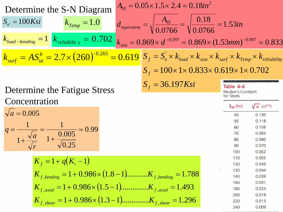
Determine the S-N Diagram
KsiS
S
kkkkkSS
f
f
yreliabilitTempsurfsizeloadef
197.36
702.01619.0833.01100
'
=
×××××=
×××××=
KsiSe 100' =
1=−bendingloadk 833.0)53.1(869.0869.0
53.10766.0
18.00766.0
18.04.25.105.0
097.0097.0
95
295
=×=×=
===
=××=
−− mmdk
inAd
inA
size
equivalent
( ) 619.02607.2 265.0 =×== −butsurf ASk
0.1=Tempk
702.0=yreliabilitk
Determine the Fatigue Stress Concentration
( )( )
( )( ) 296.1..............13.1986.01
493.1..............15.1986.01
788.1...........18.1986.01
11
,,
,,
,,
=−×+=
=−×+=
=−×+=
−+=
shearfshearf
axialfaxialf
bendingfbendingf
tf
KK
KK
KK
KqK
99.0
25.0005.01
1
1
1005.0
=+
=+
=
=
ra
q
a

43
43
2
675.012
5.14.2
728.112
4.25.16.34.25.1
inI
inI
inAArea
z
x
=×
=
=×
=
=×==
PR At the wall:
5×= PM x
25.325.600.66
25.675.1
×⎟⎠⎞
⎜⎝⎛×+×⎟
⎠⎞
⎜⎝⎛×= RRM z
( ) 25.675.16 22 =+
⎟⎠⎞
⎜⎝⎛×=
25.600.6RRy ⎟
⎠⎞
⎜⎝⎛×=
25.675.1RVx
PVz =

Point A:
A
Bx
y
z
RPRPA
R
I
M
x
x
y 266.0472.32666.0728.1
2.1525.66
24.2
−=−××
=⎟⎠⎞
⎜⎝⎛×
−⎟⎠⎞
⎜⎝⎛×
=σ
RR
AVx
yx 0583.06.3225.675.15.1
23
=×
⎟⎠⎞
⎜⎝⎛×
=××
=τ
RPy 266.0472.3 −=σ
Ryx 0583.0=τ
lbPlbPlbPlbP
AmplitudeMean
MinMax
6000........20004000.......8000==
−==
lbRLbRlbRlbR
AmplitudeMean
MinMax
1000..........01000......1000==
−==
psi
psi
Amplitudey
Meany
205661000266.06000472.3
69442000472.3
,
,
=×−×=
=×=
σ
σ
psiAmplitudeyx
Meanyx
3.5810000583.0
0
,
,
=×=
=
τ
τ

Finding the amplitude and mean Von Mises stresses at A.
psi
psi
m
mxymymxmymxm
a
axyayaxayaxa
6944036944069440
3
205663.583205660205660
3
222'
2,,,
2,
2,
'
222'
2,,,
2,
2,
'
=×+×−+=
+×−+=
=×+×−+=
+×−+=
σ
τσσσσσ
σ
τσσσσσ
Safety factors for Point A at the wall:
46.1
2600006944
3119720566
1=
+=fn
27.7694420566
200000=
+=
+=
ma
yy
Sn
σσ

A
B x
y
z
Point B:RRR
A
R
I
M
z
z
y 066.52666.0675.0
75.08.425.66
25.1
=−××
=⎟⎠⎞
⎜⎝⎛×
−⎟⎠⎞
⎜⎝⎛×
=σ
PPA
Vzyz 208.0
6.325.1
23
=××
=××
=τ
Ry 066.5=σ
Pyz 208.0=τ
lbPlbPlbPlbP
AmplitudeMean
MinMax
6000........20004000.......8000==
−==
lbRLbRlbRlbR
AmplitudeMean
MinMax
1000..........01000......1000==
−==
psipsi
Amplitudey
Meany
50661000066.50
,
,
=×=
=
σ
σ
psi
psiP
Amplitudeyz
Meanyz
12486000208.0
416208.0
,
,
=×=
=×=
τ
τ
psi
psi
m
mxymymxmymxm
a
axyayaxayaxa
72041630000
3
5508124835066050660
3
222'
2,,,
2,
2,
'
222'
2,,,
2,
2,
'
=×+×−+=
+×−+=
=×+×−+=
+×−+=
σ
τσσσσσ
σ
τσσσσσ
6.5
260000720
311975508
1=
+=fn
11.327205508
200000=
+=
+=
ma
yy
Sn
σσ

43
43
2
675.012
5.14.2
728.112
4.25.16.34.25.1
inI
inI
inAArea
z
x
=×
=
=×
=
=×==
PR
At 1in from the wall:
4×= PM x
25.325.600.65
25.675.1
×⎟⎠⎞
⎜⎝⎛×+×⎟
⎠⎞
⎜⎝⎛×= RRM z
( ) 25.675.16 22 =+
⎟⎠⎞
⎜⎝⎛×=
25.600.6RRy ⎟
⎠⎞
⎜⎝⎛×=
25.675.1RVx
PVz =

Point A:
A
Bx
y
z
RPRP
RKPK
A
RK
I
MK
y
axialfbendingfy
axialfx
x
bendingfy
397.097.4266.0493.178.27883.1
2666.0728.1
2.14
25.66
24.2
,,
,,
−=×−×=
×−××
×=
⎟⎠⎞
⎜⎝⎛×
×−⎟⎠⎞
⎜⎝⎛×
×=
σ
σ
σ
RR
AVK x
shearfyx 0755.06.3225.675.15.1
296.123
, =×
⎟⎠⎞
⎜⎝⎛×
×=××
×=τ
RPy 397.097.4 −=σ
Ryx 0755.0=τlbPlbP
lbPlbP
AmplitudeMean
MinMax
6000........20004000.......8000==
−==lbRLbR
lbRlbR
AmplitudeMean
MinMax
1000..........01000......1000==
−==
psi
psi
Amplitudey
Meany
294231000397.0600097.4
9940200097.4
,
,
=×−×=
=×=
σ
σ
psiAmplitudeyx
Meanyx
5.7510000755.0
0
,
,
=×=
=
τ
τ
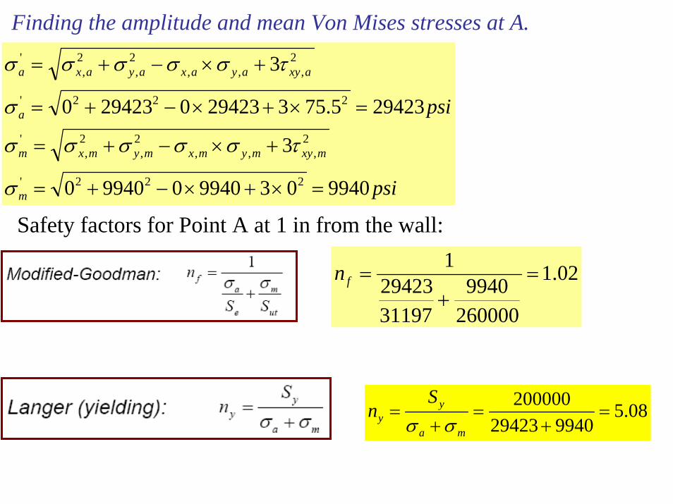
Finding the amplitude and mean Von Mises stresses at A.
psi
psi
m
mxymymxmymxm
a
axyayaxayaxa
9940039940099400
3
294235.753294230294230
3
222'
2,,,
2,
2,
'
222'
2,,,
2,
2,
'
=×+×−+=
+×−+=
=×+×−+=
+×−+=
σ
τσσσσσ
σ
τσσσσσ
Safety factors for Point A at 1 in from the wall:
02.1
2600009940
3119729423
1=
+=fn
08.5994029423
200000=
+=
+=
ma
yy
Sn
σσ

Examples of fatigue Failure
BEACH MARKSSTRIATIONS INDICATING SLOW FATIGUE
CRACK GROWTH
MULTIPLE CRACK ORIGINOVERLOAD FAILURE
Failure of a steam turbine blade from a nuclear power plant due to fatigue

A fatigue crack that started at the site of a lightning strike is shown below.

A rotating shaft loaded by the 5kN and 10kN forces is represented below. The grinding relief groove at B is 2.5mm deep. The cylindrical surface AB is ground but the groove is machined. The shaft is made of a steel hardened and tempered to SUT=1300MPa and a SYield=1000MPa according to the BS 826M40 (EN26). The shaft transmit a power of 15kW at 900RPM between the loads. A safety factor (on load) of 2 corresponding to a life of 0.35x10⁶ cycles has been used for the shaft design. Is the design correct? If not determine the new life for a S.F.=2. The shaft operates at room temperature with a reliability of 99.9%.
Quiz

Kbending=1.63……KTorsion=1.32
Determine the Fatigue Stress Concentration
( )( )( ) 305.1..............132.1954.01
601.1...........163.1954.01
11
,,
,,
=−×+=
=−×+=
−+=
shearftorsionf
bendingfbendingf
tf
KK
KK
KqK
954.0
4.2550215.01
1
1
10215.0
=+
=+
=
=
ra
q
a
1300MPa=188.5ksi

Determine the S-N Diagram
MPaS
S
kkkkkSS
f
f
yreliabilitTempsurfsizeloadef
278
753.016745.08422.01650
'
=
×××××=
×××××=
MPaSe 650' = 1=−bendingloadk
( ) 6745.0130051.4 265.0 =×== −butsurf ASk
0.1=Tempk
753.0=yreliabilitk8422.0)35(189.1189.1
350766.0
835.930766.0
835.93350766.00766.0
097.0097.0
95
22295
=×=×=
===
=×==
−− mmdk
mmAd
mmdA
size
equivalent
0.9x1300=1170MPa
278MPa
3.5x10⁵MPaS
S
S
aNbS
f
f
f
f
95.345
539.2)log(
)4.4922log()105.3log()10log()10log()278log()1170log()log(
)log()log()log(
563
=
=
+××−−
=
+×=
208.0278
1170log31log1
−=⎟⎠⎞
⎜⎝⎛−=⎟⎟
⎠
⎞⎜⎜⎝
⎛=
e
m
SS
zb
bn aNS =
N2 (106) z1.0 -3.0005.0 -3.69910.0 -4.00050.0 -4.699100.0 -5.000500.0 -5.699
4.492269218.3)log()208.0(3)1170log(3)log()log(
=⇒=−×−=−=
aabSa m
NbSaNbaS
n
n
log)log(logloglog)log(
−=+=
345.95MPa

mNRmNRRM A
−=⇒⇒−=×−×+×==∑
428.6571.83501025010050
12
2
642.8N-m
857N-m
MC=214.3N-mMB=749.9N-mMA=160.7N-m
mNT
wattsPmNTrpmnnTP
−=××
=
−=
15.1599002
1500060
)()...()..(....60
2
π
π
T=159.15N-m
Critical point at B:MB=749.9N-mTB=159.15N-m
Bending moment gives the stress amplitude, while the Torque gives the mean stress.
JcTK
IcMK
torquemeantorque
bendingamplitudebending
××=
××=
,
,
τ
σ
( )
( ) 484
484
1073.14035.032
10366.7035.064
mJ
mI
−
−
×==
×==
π
π
6.428kN
1.428kN
8.571kN

( )( )( )
MPamNI
cMK
amp
bendingamplitudebending
23.28510366.7
2035.09.749
601.1 8
,
=×
−×=
××=
−σ
σ
( )( )( )
MPamN
JcTK
mean
torquemeantorque
68.241073.14
2035.015.159
305.1 8
,
=×
−×=
××=
−τ
τ
Finding the Von Mises stresses
( ) MPaMPa
MPa
mVM
aVM
74.4268.243
23.2852
,
,
=×=
=
σ
σ
Modified Goodman
17.1..1300
74.4295.34523.285
..1
=⇒+= FSFS
Langer
05.374.4223.285
1000,,
=+
=+
=MPaMPa
MPaLangerSFampVMmeanVM
Yield
σσσ
Calculating the new life
MPaNN
2.5741300
74.4223.28521
=⇒+= σσ
( )
cyclesN
N
baS
NaNbS ff
30620
486.4208.0
)4.4922log()2.574log()log(
)log()log()log()log()log()log(
=
=−−
=
−=⇒+×=


![6. Wiring Diagram - weidefamily.net coil Transmission control module ... WIRING DIAGRAM 6. Wiring Diagram. MEMO: 21 WIRING DIAGRAM ... 76 6-3 [D6R2] WIRING DIAGRAM 6.](https://static.fdocuments.us/doc/165x107/5aa0cc3b7f8b9a62178ea5e7/6-wiring-diagram-coil-transmission-control-module-wiring-diagram-6-wiring.jpg)